PBE Europe as Axell Wireless A217SERIES Tri-Band Repeater MBF-T-7-8-19 User Manual High Selectivity Digital 900MHz Repeater
Axell Wireless Tri-Band Repeater MBF-T-7-8-19 High Selectivity Digital 900MHz Repeater
manual
AXELL MBF MULI-BAND FIBRE REPEATER
PRODUCT DESCRIPTION AND USER’S MANUAL
MBF, Multi Band Repeater
Product Description and User’s Manual
THIS DOCUMENT IS VALID FOR SINGLE-BAND, DUAL-BAND AND TRI-BAND MBF
REPEATERS SUPPORTING THE FOLLOWING FREQUECY BANDS:
LTE 700, 850, 900, 1800, 1900, 2200 and AWS
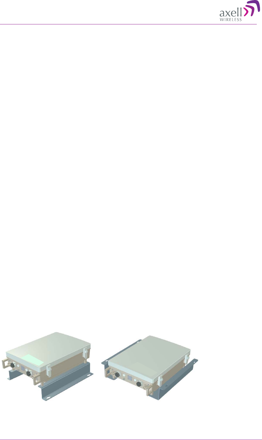
Single or dual band repeater
Tri band repeater
AXELL MBF MULI-BAND FIBRE REPEATER
PRODUCT DESCRIPTION AND USER’S MANUAL
II © Axell Wireless Ltd
Copyright © 2011 Axell Wireless Ltd
All rights reserved.
No part of this document may be copied, distributed, transmitted, transcribed, stored in a retrieval system, or
translated into any human or computer language without the prior written permission of Axell Wireless Ltd.
The manufacturer has made every effort to ensure that the instructions contained in this document are
adequate and free of errors and omissions. The manufacturer will, if necessary, explain issues which may not
be covered by this document. The manufacturer's liability for any errors in the document is limited to the
correction of errors and the aforementioned advisory services.
This document has been prepared to be used by professional and properly trained personnel, and the
customer assumes full responsibility when using them. The manufacturer welcomes customer comments as
part of the process of continual development and improvement of the documentation in the best way possible
from the user's viewpoint. Please submit your comments to the nearest Axell Wireless sales representative.
Contact Information
Headquarters
Axell Wireless
Aerial House
Asheridge Road
Chesham
Buckinghamshire HP5 2QD
United Kingdom
Tel: +44 1494 777000
Fax: +44 1494 777002
Commercial inquiries
info@axellwireless.com
Web site
www.axellwireless.com
Support issues
support@axellwireless.com
Technical Support Line, English speaking
+44 1494 777 777
Contact information for Axell Wireless offices in other countries can be found on our web site,
www.axellwireless.com

AXELL MBF MULI-BAND FIBRE REPEATER
PRODUCT DESCRIPTION AND USER’S MANUAL
© Axell Wireless Ltd III
About This Manual
This Product Manual provides the following information:
• Description of the Repeater unit
• Procedures for setup, configuration and checking the proper operation of the unit
• Maintenance and troubleshooting procedures
For whom it is Intended
This Product Manual is intended for experienced technicians and engineers. It is assumed that the
customers installing, operating, and maintaining Axell Wireless Repeaters are familiar with the basic
functionality of Repeaters.
Notice
Confidential - Authorized Customer Use
This document may be used in its complete form only and is solely for the use of Axell Wireless
employees and authorized Axell Wireless channels or customers. The material herein is proprietary to
Axell Wireless. Any unauthorized reproduction, use or disclosure of any part thereof is strictly
prohibited.
All trademarks and registered trademarks are the property of their respective owners.
Disclaimer of Liability
Contents herein are current as of the date of publication. Axell Wireless reserves the right to change
the contents without prior notice. The information furnished by Axell Wireless in this document is
believed to be accurate and reliable. However, Axell Wireless assumes no responsibility for its use.
In no event shall Axell Wireless be liable for any damage resulting from loss of data, loss of use, or
loss of profits and Axell Wireless further disclaims any and all liability for indirect, incidental,
special, consequential or other similes damages. This disclaimer of liability applies to all products,
publications and services during and after the warranty period.
Warrantee
All antennas must be installed with Lightning protection. Damage to power modules, as a result of
lightning are not covered by the warranty.
Switching on AC or DC power prior to the connection of antenna cables is regarded as faulty
installation procedure and therefore not covered by the Axell Wireless warranty.
AXELL MBF MULI-BAND FIBRE REPEATER
PRODUCT DESCRIPTION AND USER’S MANUAL
IV © Axell Wireless Ltd
Safety to Personnel
Before installing or replacing any of the equipment, the entire manual should be read and understood.
The user needs to supply the appropriate AC or DC power to the OMU System. Incorrect power
settings can damage the OMU System and may cause injury to the user.
Throughout this manual, there are "Caution" warnings. "Caution" calls attention to a procedure or
practice, which, if ignored, may result in injury or damage to the system, system component or even
the user. Do not perform any procedure preceded by a "Caution" until the described conditions are
fully understood and met.
CAUTION! This notice calls attention to a procedure or practice that, if ignored, may result in
personal injury or in damage to the system or system component. Do not perform any procedure
preceded by a "Caution" until described conditions are fully understood and met.
Safety to Equipment
When installing, replacing or using this product, observe all safety precautions during handling and
operation. Failure to comply with the safety precautions and with specific precautions described
elsewhere in this manual violates the safety standards of the design, manufacture, and intended use of
this product. Axell Wireless assumes no liability for the customer's failure to comply with these
precautions. This entire manual should be read and understood before operating or maintaining the
OMU System.
Class 3B Laser
This product is equipped with class 3B lasers, as per definition in EN 60825-1.
Caution!!!
Un-terminated optical receptacles may emit laser radiation.
Do not stare into beam or view with optical instruments.
Optical transmitters in the opto-module can emit high energy invisible laser radiation. There is a risk
for permanent damage to the eye.
Always use protective cover on all cables and connectors which are not connected. Never look
straight into a fibre cable or a connector. Consider that a fibre can carry transmission in both
directions.
During handling of laser cables or connections ensure that the source is switched off. Regard all open
connectors with respect and direct them in a safe direction and never towards a reflecting surface.
Reflected laser radiation should be regarded as equally hazardous as direct radiation.

AXELL MBF MULI-BAND FIBRE REPEATER
PRODUCT DESCRIPTION AND USER’S MANUAL
© Axell Wireless Ltd V
Radiation Hazard
This equipment emits radio frequency radiation and can, if used the wrong way, be hazardous for
personnel. Here follows an example of the power densities from an intentional radiator.
For radiation from a general antenna, the power density (S) at some distance is according to the well-
known formula:
For the repeaters described in this handbook the maximum output powers are 5 W for 900 / 1800
MHz and 10 W 2100 MHz. The corresponding power densities using a + 10 dBi antenna as an
example at 1 m will be 4 W/ m² for the 900/1800 MHz output and 8 W/ m² for 2100 MHZ output.
1 m distance from the antenna at these frequencies is used as a minimum distance for practical
exposure of the public. It is also difficult to have a developed EMF at distances closer than 1 m.
According to R&TTE Health requirements referring to the 1999 Council recommendation, the
reference level for the frequency range of 400 – 2000 MHz is f/ 200 W/ m² ( f in MHz ) and above 2
GHz, 10 W/ m².
For the repeaters in this manual the levels are:
GSM 900 (960 MHz) = 4.8 W/m²
DC 1800 (1880 MHz) = 9.4 W/m²
UMTS 2100 (2170 MHz) = 10 W/m².
This means that an installation with a +10 dBi antenna does not exceed the basic restriction levels
according to the recommendations.
For frequencies between 400 and 2000 MHz the ICNIRP occupational guideline level of exposure is f
/40 W/m² (f in MHz), and 50 W/m² for frequencies above 2 GHz.
The ICNIRP levels for the frequency above bands:
GSM 900 (960 MHz) = 24 W/m²
DC 1800 (1880 MHz) = 47 W/m²
UMTS 2100 (2170 MHz) = 50 W/m².
There are no radiation health issues with the above + 10 dBi antenna installations. However, the
repeater is marked with radiation hazard warning.

AXELL MBF MULI-BAND FIBRE REPEATER
PRODUCT DESCRIPTION AND USER’S MANUAL
VI © Axell Wireless Ltd
Standards
This document covers both GSM and WDCMA repeaters. These references are valid for respective
repeater type.
ETSI TS 25.106
Universal Mobile Telecommunications System (UMTS); UTRA
repeater radio transmission and reception 3GPP TS 25.106 version
5.8.0 Release 5)
ETSI TS 25.143
Universal Mobile Telecommunications System (UMTS); UTRA
repeater conformance testing (3GPP TS 25.143 version 5.8.0
Release 5)
ETSI EN 301 908-3
Electromagnetic compatibility and Radio spectrum Matters (ERM);
ElectroMagnetic Compatibility (EMC) standard for radio
equipment and services; Part 1: Common technical requirements
ETSI EN 301 489-23
Electromagnetic compatibility and Radio spectrum Matters (ERM);
ElectroMagnetic Compatibility (EMC) standard for radio
equipment and services; Part 23: Specific Conditions for IMT-2000
CDMA Direct Spread (UTRA) Base Station (BS) radio, repeater
and ancillary equipment
EN 60 950 Information technology equipment - Safety - Part 1: General
requirements
EN 301 502
Harmonized EN for Global System for Mobile communications
(GSM); Base station and Repeater equipment covering essential
requirements under article 3.2 of the R&TTE directive (GSM 13.21
version 8.1.2. Release 1999)
ETS 300 342-3
Radio Equipment and Systems (RES); Electro-Magnetic
Compatibility (EMC) for European Digital Cellular
Telecommunications systems. Base Station Radio and ancillary
equipment and Repeaters meeting phase 2 GSM requirements.
R & TTE Directive:
ETS EN 301 502
(ETS EN 300 609-
4/GSM 11.26)
Harmonized EN for Global System for Mobile communications
(GSM); Base Station and Repeater equipment covering essential
requirements under article 3.2 of the R&TTE directive
ETS EN 301 489-8
Electromagnetic Compatibility (EMC) Standard For Radio
Equipment And Services; Part 8: Specific Conditions For GSM
Base Stations
ETS 300 342-3
Electromagnetic Compatibility (EMC) For European Digital
Cellular Telecommunications System (GSM 900 MHz and DCS 1
800 MHz); Part 3: Base Station Radio and Ancillary Equipment
And Repeaters Meeting Phase 2 GSM Requirements

AXELL MBF MULI-BAND FIBRE REPEATER
PRODUCT DESCRIPTION AND USER’S MANUAL
© Axell Wireless Ltd VII
Electrostatic Sensitivity
Observe electrostatic precautionary procedures.
Caution
ESD = Electrostatic Discharge Sensitive Device
Semiconductor transmitters and receivers provide highly reliable performance when operated in
conformity with their intended design. However, a semiconductor may be damaged by an
electrostatic charge inadvertently imposed by careless handling.
Static electricity can be conducted to the semiconductor chip from the centre pin of the RF input
connector, and through the AC connector pins. When unpacking and otherwise handling the unit,
follow ESD precautionary procedures including use of grounded wrist straps, grounded workbench
surfaces, and grounded floor mats.
.

AXELL MBF MULI-BAND FIBRE REPEATER
PRODUCT DESCRIPTION AND USER’S MANUAL
© Axell Wireless Ltd VIII
Table of Contents
1 Introduction ................................................................................................................. 1
1.1 General Information on Installation Approach .................................................................. 1
1.2 Models and Ordering Information ...................................................................................... 2
1.3 Characteristics ..................................................................................................................... 2
1.4 ALC ........................................................................................................................................ 3
1.5 Operating Temperature ....................................................................................................... 3
1.6 MBF Interfaces ...................................................................................................................... 3
1.6.1 Securing the Unit ....................................................................................................... 4
1.6.2 External Interfaces..................................................................................................... 4
1.6.3 Internal Interfaces ...................................................................................................... 5
2 Installation ................................................................................................................... 7
2.1 Unpacking ............................................................................................................................. 7
2.1.1 Unpack the Unit ......................................................................................................... 7
2.2 Mount the Repeater .............................................................................................................. 7
2.2.1 Ensure Proper Cooling .............................................................................................. 8
2.3 Grounding ............................................................................................................................. 8
2.4 Ensure Good EMV Protection ............................................................................................. 9
2.5 Fibre Optic Connection...................................................................................................... 10
2.5.1 Cleaning Optical Connectors ................................................................................... 12
2.6 External Alarm and Relay Connections ........................................................................... 13
2.7 Power and Backup Battery ................................................................................................ 14
2.7.1 Connecting the Power Source ................................................................................. 14
2.7.2 230 VAC Power Source .......................................................................................... 15
2.7.3 -48V Power Source Connection .............................................................................. 16
2.7.4 Backup Battery ........................................................................................................ 17
2.8 Power ON ............................................................................................................................ 17
2.8.1 Switching Power ON................................................................................................ 17
2.8.2 Verifying LEDs ......................................................................................................... 18
2.9 Closing and Securing the Repeater ................................................................................. 18
3 Commissioning Advice............................................................................................. 19
3.1 Signal Diagrams ................................................................................................................. 19
3.2 OMU Point of Interface (POI) ............................................................................................. 20
3.3 Downlink POI / OMU DL Attenuator Adjustment ............................................................. 20
3.4 Repeater Downlink Optical Link Adjustment (OLA) ....................................................... 22
3.5 Downlink Repeater Gain Adjustment ............................................................................... 22
3.6 UMTS Signal Measurement ............................................................................................... 24
3.6.1 Bandwidth ................................................................................................................ 24
3.6.2 Traffic ....................................................................................................................... 24
4 Setup .......................................................................................................................... 25
4.1 Open a Local Session ........................................................................................................ 26
4.2 Set Repeater Name (TAG) ................................................................................................. 27
4.3 TCP/IP and Ethernet Communication .............................................................................. 28
4.4 Set-up RF Configuration .................................................................................................... 29
4.5 For Stand-alone Repeaters – Modem Communication .................................................. 31

AXELL MBF MULI-BAND FIBER REPEATER
PRODUCT DESCRIPTION AND USER’S MANUAL
© Axell Wireless Ltd IX
4.6 AEM Addresses .................................................................................................................. 31
4.7 Integration into the AEM .................................................................................................... 31
5 Troubleshooting ........................................................................................................32
5.1 Module LEDs ....................................................................................................................... 32
5.1.1 Control Module LEDs .............................................................................................. 32
5.1.2 F/O Converter .......................................................................................................... 33
5.1.3 Power Supply LEDs ................................................................................................ 33
6 Maintenance...............................................................................................................35
6.1 General ................................................................................................................................ 35
6.2 Preventative Maintenance ................................................................................................. 35
6.3 Trouble Shooting................................................................................................................ 35
6.4 Component Replacement .................................................................................................. 35
6.5 Product Disposal ................................................................................................................ 36
7 Modem Communication ............................................................................................37
7.1 Modem Initialization ........................................................................................................... 37
7.2 Monitoring Modem Connection ........................................................................................ 37
7.3 Scheduled Modem Power Cycling.................................................................................... 37
7.4 Communication via Wireless Modem .............................................................................. 38
7.4.1 Modem Configuration, not using GPRS .................................................................. 38
7.4.2 Modem Configuration, using GPRS ........................................................................ 39
7.4.3 Configuration via PSTN (Fixed) Modem ................................................................. 41
7.5 Troubleshooting Remote Communication ...................................................................... 42
7.5.1 Direct Modem Access ............................................................................................. 43
7.5.2 Trace Modem .......................................................................................................... 43
7.5.3 Manually Answering Incoming Calls........................................................................ 44
7.5.4 Common Problems .................................................................................................. 45
8 Specifications ............................................................................................................48
8.1 Single Band Repeater MBF-S-7/8/9/17/18/19/22 .............................................................. 48
8.2 Dual Band Repeater MBF-D-9-22/8-19/7-17 ..................................................................... 50
8.3 Tri Band Repeater MBF-T-9-18-22/8-17-19 ....................................................................... 52
AXELL MBF MULI-BAND FIBRE REPEATER
PRODUCT DESCRIPTION AND USER’S MANUAL
© Axell Wireless Ltd 1
1
1
I
In
nt
tr
ro
od
du
uc
ct
ti
io
on
n
Axell MBF (Multi Band Fibre) family of repeaters comprises of three types of fibre fed repeaters:
single-band, dual-band and tri-band. The repeaters are available in various models supporting
frequency bands LTE 700, 850, 900, 1800, 1900, 2200 and AWS.
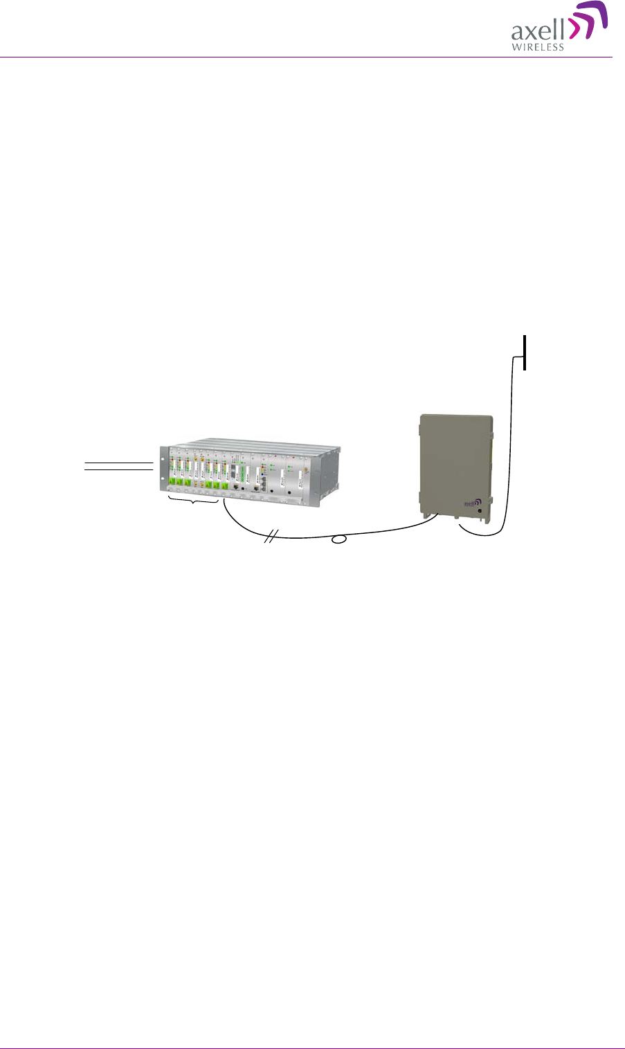
The MBF repeater RF signal is supplied via an optic fibre connection to the Axell Optical Master
Unit (OMU). The OMU is located at the Base Station RF signal source and converts the RF signal to
an optical signal for routing to Repeaters via a fibre optic connection. Each OMU can support up to
six repeaters.(The OMU is described in detail in the OMU User Manual).
Figure 1-1Standard OMU-Repeater application where one OMU is used
1
1.
.1
1
G
Ge
en
ne
er
ra
al
l
I
In
nf
fo
or
rm
ma
at
ti
io
on
n
o
on
n
I
In
ns
st
ta
al
ll
la
at
ti
io
on
n
A
Ap
pp
pr
ro
oa
ac
ch
h
• Single, dual and tri-band models supporting LTE 700, 850, 900, 1800, 1900, 2200 and AWS
• The Repeater door opens to provide access to internal connections
• The door is secured with two screws and a lock
• F/O, power and alarm connections are inserted via the panel interfaces and connected internally
• GND and RF service antennas are connected externally
• Local setup via RS232 connection is accessed internally
• Same mounting brackets are used for either wall or rack mount (different assembly positions)
• Backup battery for ‘last gasp’ modem indication (sending fault error before power failure)
• Can connect to either 110/230 VAC or -48V power
RF
MBF
Repeater
Opto Fiber
RF
FiberOptic
Converters
Server
Antenna
From BTS
via coupler
OMU
AXELL MBF MULI-BAND FIBRE REPEATER
PRODUCT DESCRIPTION AND USER’S MANUAL
2 © Axell Wireless Ltd
1
1.
.2
2
M
Mo
od
de
el
ls
s
a
an
nd
d
O
Or
rd
de
er
ri
in
ng
g
I
In
nf
fo
or
rm
ma
at
ti
io
on
n
Each of the three MBF repeater types are provided in a wide range of models. The following tables
list the most models available for single-, dual- and tri-band type repeaters.
The models are named according to the following conventions:
• Letters indicating number of bands: “S” (single band), “D” (dual band), “T” (tri band)
• Numbers indicating frequencies: “7” (700MHz), “8” (850MHz, “9” (900 MHz), “18”
(1800MHz), “19” (1900 MHz), “22” (2100MHz) and “17” (AWS band).
Single Band
MBF-S-7
LTE-700
MBF-S-8
GSM/WCDMA850
MBF-S-9
E-GSM
MBF-S-18
GSM1800
MBF-S-19
GSM/WCDMA1900
MBF-S-22
WCDMA2100
Dual Band
MBF-D-9-22
E-GSM and WCDMA2100
MBF-D-8-19
GSM/WCDMA850 and GSM/WCDMA1900
MBF-D-7-17
LTE700 and AWS
Tri Band
MBF-T-9-18-22
E-GSM, GSM1800 and WCDMA2100
MBF-T-8-17-19
GSM/WCDMA850, AWS and
GSM/WCDMA1900
MBF-T-7-8-19
LTE700,GSM/WCDMA850,GSM/CDMA1900
1
1.
.3
3
C
Ch
ha
ar
ra
ac
ct
te
er
ri
is
st
ti
ic
cs
s
The following table lists the Composite DL Output Power for the most common bands.
Composite output DL power per band
Band
Composite Output DL Power
850MHz
+37 dBm
E-GSM
+37 dBm*
700MHz
+37dBm
1800MHz
+37 dBm*
1900MHz
+37 dBm
2100MHz
+39 dBm
Gain is defined by the whole
link including the OMU
Adjustable in 1dB steps
Note: In repeaters that share a common downlink fibre for 900MHZ and 1800MHz a minimum of 4
carriers in each band is required for the full composite output power to be attainable maintaining full
ETSI compliance.
AXELL MBF MULI-BAND FIBER REPEATER
PRODUCT DESCRIPTION AND USER’S MANUAL
© Axell Wireless Ltd 3
1
1.
.4
4
A
AL
LC
C
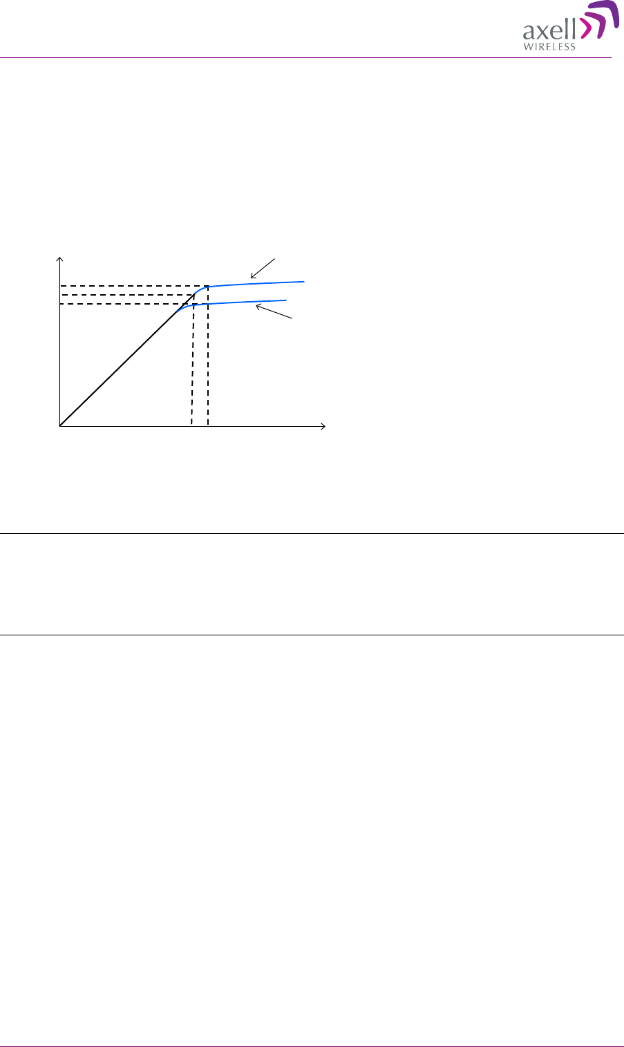
The repeater has a constant gain in both uplink and downlink paths. The gain is set by defining the
attenuation as described above.
The repeater has a defined maximum output level. If the input signal amplified by the gain set
exceeds the set output limit, an ALC (Automatic Level Control) loop is activated. This ALC ensures
that the amplifier does not add distortion to the radio signal. Below are examples of the ALC function
for one and two carriers.
1
1.
.5
5
O
Op
pe
er
ra
at
ti
in
ng
g
T
Te
em
mp
pe
er
ra
at
tu
ur
re
e
Note! The MBF repeaters are designed primarily for multi carrier purposes. If the repeaters are run
at full output power over a longer period the convection cooling might not be enough. The repeaters
have a power management function implemented that will step down the power and if needed fully
shut down the amplifier chains until temperature has reached normal values. In situations where a
repeater will be run in such a manner extra cooling can be provided for instance by putting the
repeater in a temperature controlled environment or via external fans.
1
1.
.6
6
M
MB
BF
F
I
In
nt
te
er
rf
fa
ac
ce
es
s
The MBF unit provide three types of interfaces:
• Securing interfaces – lock and screws for security
• Panel connections to RF, communication and power
• Internal connections for local setup and for connecting optic fibres and power connections that
are routed in from the
ALC one carrier
Input signal, dBm
Output power, dBm
+36,5
+33,8
-24 -16
Gain: 60 dB
+35
ALC two carriers
AXELL MBF MULI-BAND FIBRE REPEATER
PRODUCT DESCRIPTION AND USER’S MANUAL
4 © Axell Wireless Ltd
1.6.1 Securing the Unit
The repeaters are secured with two hex
screws (M8) and can also be locked with a
key.
Note! The two screws must be fully
tightened. Failure to do so may affect the
IP65 compliancy and therefore any
warranty.
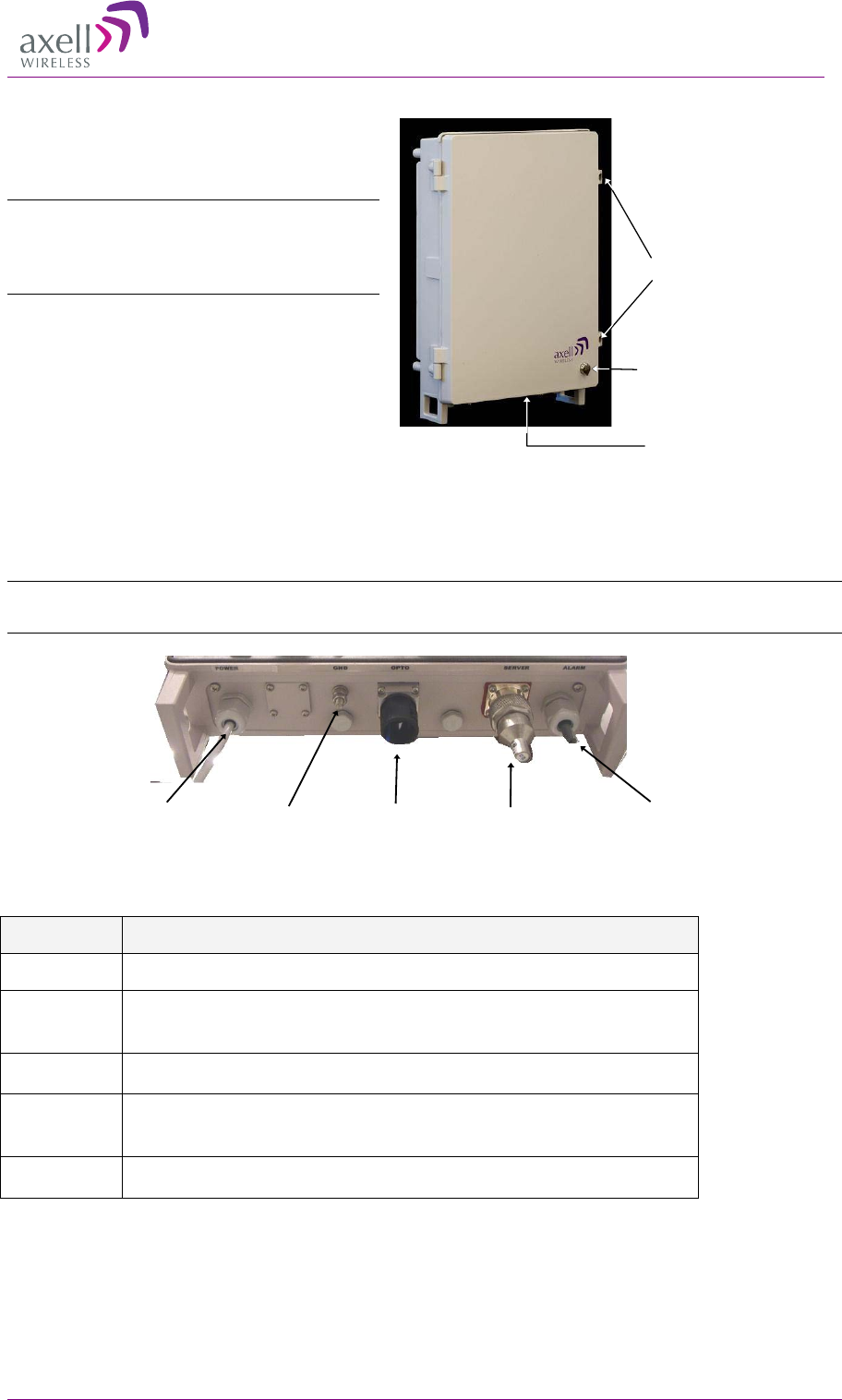
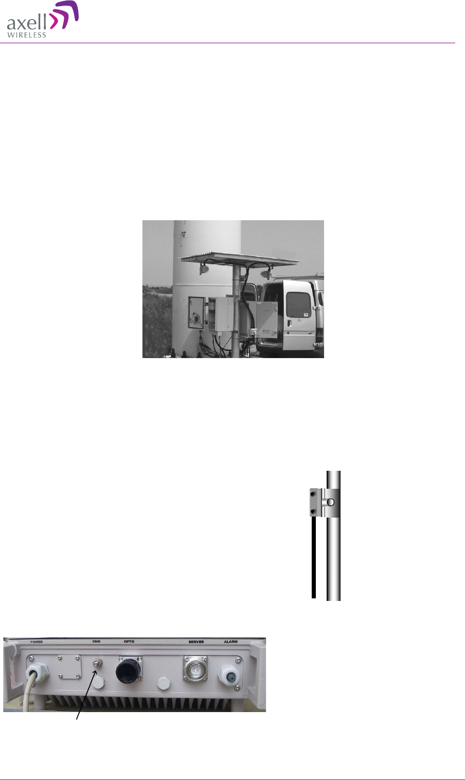
1.6.2 External Interfaces
The repeater’s interfaces are located on the underside panel.
Note! The external connections at the bottom of the repeater can be protected with a cover which is
screwed in place.
The following table provides a description of the front panel ports and connections.
Port Description
Server Service antenna connection - DIN 7/16” connector, female
Optic SC/APC fibre optic connector through which the optic fibre is routed for
internal connections (section 2.5).
Power Plinth connection for routing power for internal connection (section 2.7)
Alarms Plinth connector for routing external alarms and relay wiring cable for
internal connections (section 2.6).
GND Grounding lug (section 2.3)
Screws
Connectors
Lock
Power Fiber inputGround Server
antenna External
alarms
AXELL MBF MULI-BAND FIBER REPEATER
PRODUCT DESCRIPTION AND USER’S MANUAL
© Axell Wireless Ltd 5
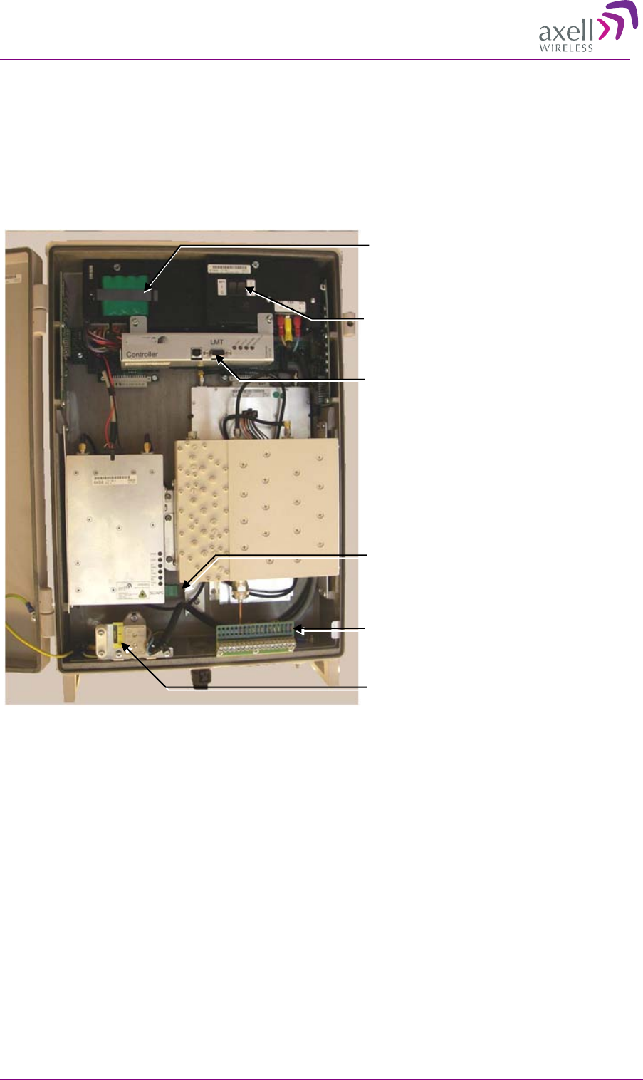
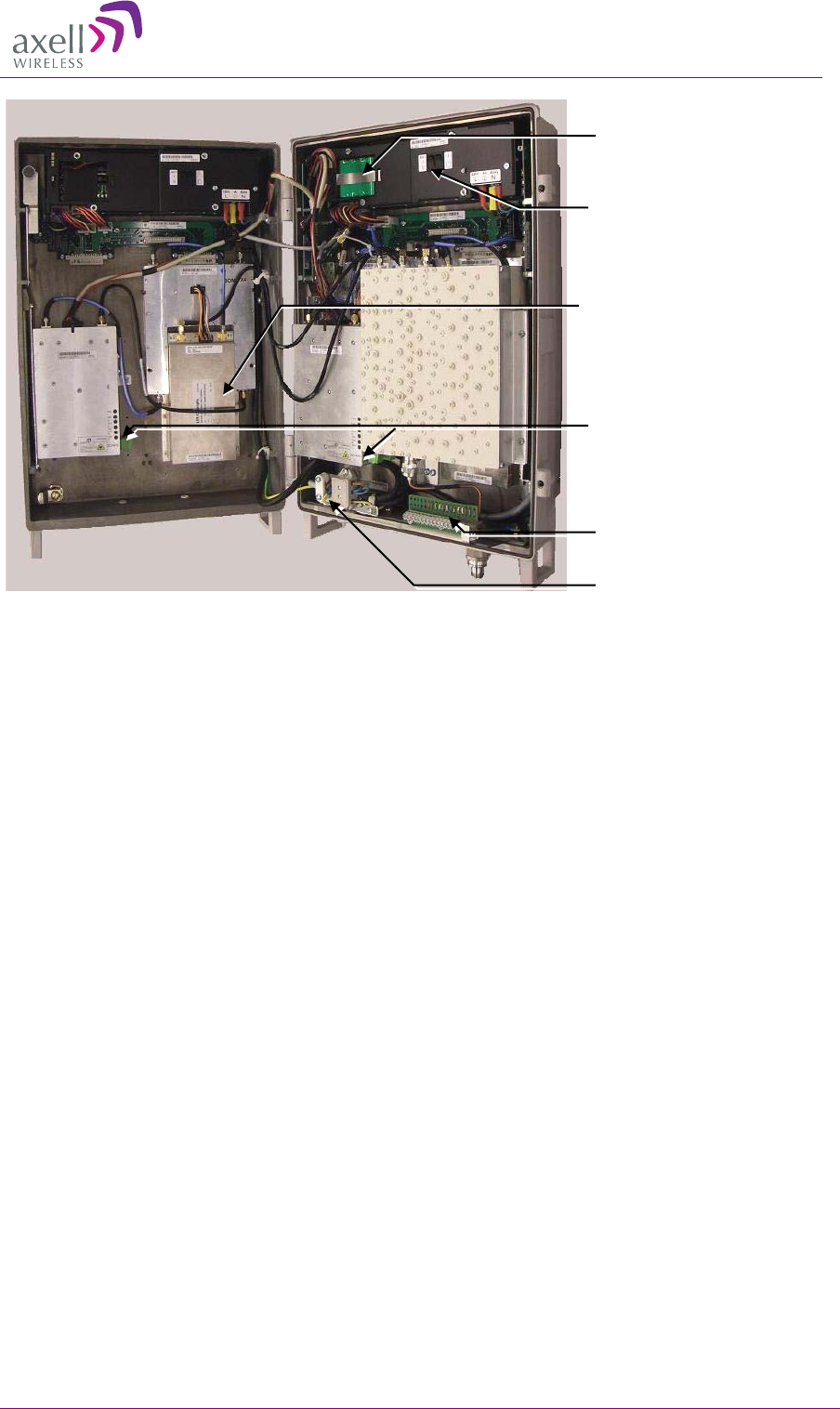
1.6.3 Internal Interfaces
You will need to open the Repeater in order to:
• Connect power and optic fibres
• Connect alarms (if relevant)
• Power up the Repeater
• Connect to the LMT (RS232 connection) for local setup
1-2. Single band repeater with door open
Controller module RS232 local
setup connection. Refer to section
4.1.2 for LED descriptions
Alarms and relay connections.
Refer to section 2.7 for
descriptions.
F/O Converter LEDs (section
4.1.1) and optic connector to
which routed optic fibre is
connected (section 2.6)
Power connections.
Controller module RS232 local
setup connection. Refer to section
4.1.2 for LED descriptions
Rechargeable battery pack
Power and battery switches
AXELL MBF MULI-BAND FIBRE REPEATER
PRODUCT DESCRIPTION AND USER’S MANUAL
6 © Axell Wireless Ltd
1-3. Dual-band MBF model
Alarms and relay
connections. Refer to section
2.7 for descriptions.
Two F/O Converters:
LEDs (described in section
4.1.1), F/O connector (section
2.6)
Controller module RS232
local setup connection. Refer
to section 4.1.2 for LED
descriptions
Power connections ( 2.7)
Rechargeable battery pack
Power and battery switches
AXELL MBF MULI-BAND FIBER REPEATER
PRODUCT DESCRIPTION AND USER’S MANUAL
© Axell Wireless Ltd 7
2
2
I
In
ns
st
ta
al
ll
la
at
ti
io
on
n
2
2.
.1
1
U
Un
np
pa
ac
ck
ki
in
ng
g
2.1.1 Unpack the Unit
Inspect the shipped material before unpacking the equipment, document any visual damage and
report according to routines.
A delivery of a repeater from Axell Wireless contains:
• Checklist with delivered items
• Repeater
• Mounting brackets
• 4 bolts for attaching repeater to mounting kit
• Cable cover
• Keys to repeater and insex tool for bolts
• Hose for fibre inlet
• CD containing User’s Manual and RMC
Any other specifically ordered item
2
2.
.2
2
M
Mo
ou
un
nt
t
t
th
he
e
R
Re
ep
pe
ea
at
te
er
r
Mount the repeater on a wall, on a pole or in a rack.
Mount the repeater in an accessible location and in a location that fulfils the environmental
requirements.
The repeater can be mounted on the wall or in a 19 inch rack. The Repeater is delivered with
mounting brackets.
The repeater needs to be mounted tightly to eliminate vibration.
Mounting bracket position for wall
mounting
Mounting bracket position for rack
mounting
AXELL MBF MULI-BAND FIBRE REPEATER
PRODUCT DESCRIPTION AND USER’S MANUAL
8 © Axell Wireless Ltd
2.2.1 Ensure Proper Cooling
• Mount the repeater so that heat can be dispersed from it.
• The repeater wall mounting kit ensures an optimum airflow between the wall and the repeater
itself.
• Do not block this air channel as it will cause the MTBF of the repeater to drop dramatically, or
even in the worst case cause the repeater to fail completely.
• If possible use a wall in the shadow to minimize the overall sun loading. If sufficient shielding
cannot be obtained, an additional sun shield should be mounted.
2-1. Example of a sun shield
2
2.
.3
3
G
Gr
ro
ou
un
nd
di
in
ng
g
• Connect the grounding protection.
• Ensure that good grounding protection measures are taken to
create a reliable repeater site.
• Make sure to use adequately dimensioned grounding cables.
The minimum recommended conductive area for a
grounding cable is 16mm2
• The antenna cabling should be connected to ground every
10m by a reliable grounding kit.
• Make sure the grounding product used is suitable for the kind
and size of cable being used.
• Connect the repeater box bolt to the same ground.
Ground
AXELL MBF MULI-BAND FIBER REPEATER
PRODUCT DESCRIPTION AND USER’S MANUAL
© Axell Wireless Ltd 9
2
2.
.4
4
E
En
ns
su
ur
re
e
G
Go
oo
od
d
E
EM
MV
V
P
Pr
ro
ot
te
ec
ct
ti
io
on
n
Caution
If insufficient Electromagnetic Protection is provided,
or if EMV measures are not taken, warranties issued by Axell Wireless are not valid.
Connect the
lightning
protection
The lightning hazard to electric and electronic equipment consists in the interferences of
direct lightning current infections and high surge voltages induced by the electromagnetic
field of nearby lightning channels or down conductors. Amplitudes from cloud-to-earth
lightning amounts to several 10kA and may last longer than 2 ms. The damage caused
depends on the energy involved and on the sensitivity of the electronics systems.
Ensure that lightning protection measures are taken to create a reliable repeater site. Protect
all coaxial cables and power cables from the transients caused by lightning. Fit all cables
with suitable lightning protection devices.
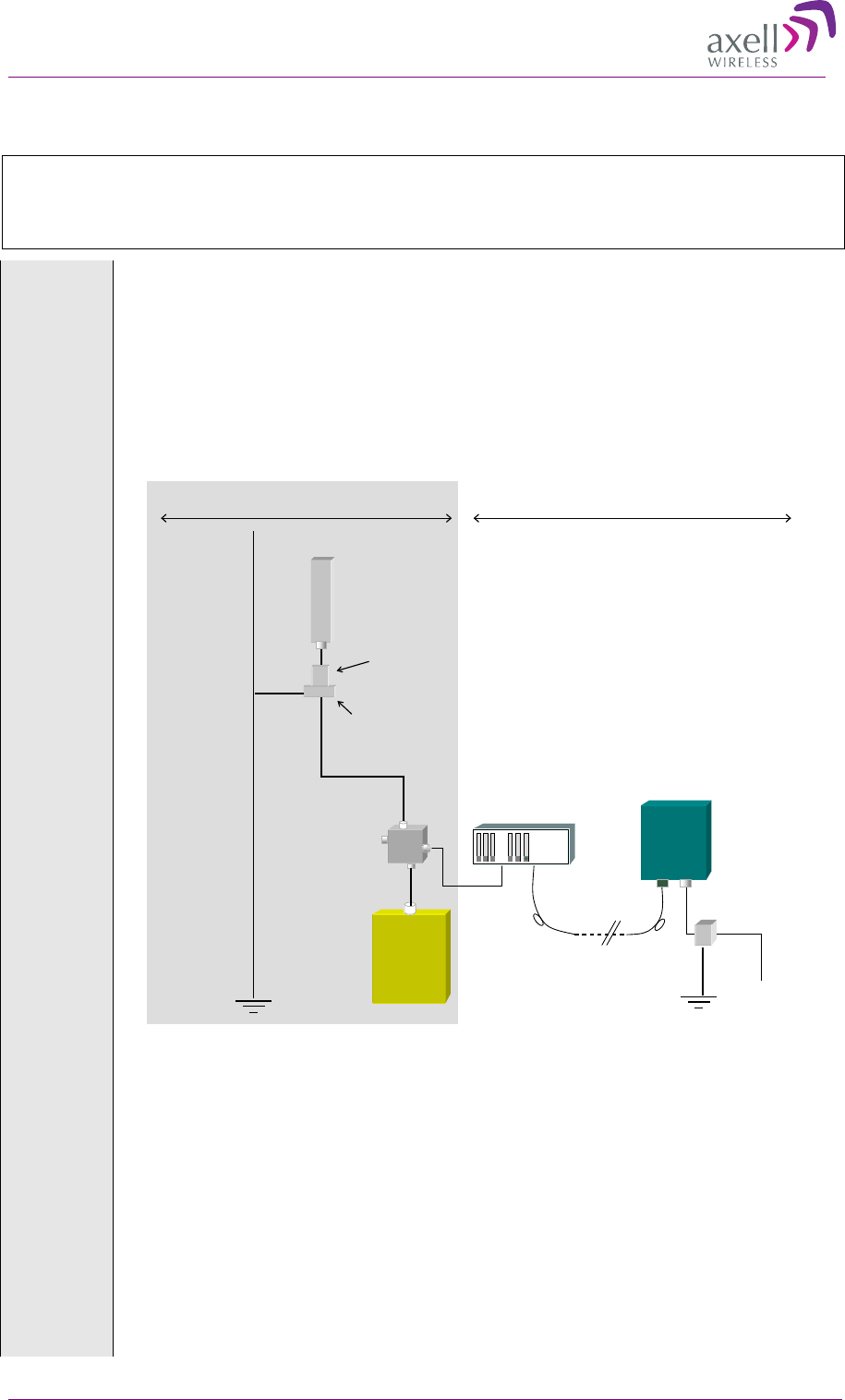
Example of EMV protection for a repeater system
For detailed information please refer to IEC 61024-1 and 61312-1 for international
standards for protection of information systems against LEMP, Lightning Electromagnetic
Pulse, including radio transmitters. They define proper planning, installation and
inspection of effective lightning protection systems.
The Axell Wireless repeaters comply with the EN standard ETS 301 498-8 which
stipulates demands on lightning/surge protection for typical infrastructure telecom
equipment installations.
Several lightning protection devices should be used in series with declining threshold
voltages to help attenuate the pulse component which makes it through the first layer of
protection.
Repeater
Fiber
BTS
-30dB
Coupler
OMU
Antenna
Primary
Protective
Device
Equipotential
Grounding Bar
230VAC/
-48VDC
Protective
Device
The top of
the mast
must be
higher than
the antennas
and be
grounded
properly
The
grounding
path must
have reliable
continuity
and be
dimensioned
correctly
BTS area Repeater area
AXELL MBF MULI-BAND FIBRE REPEATER
PRODUCT DESCRIPTION AND USER’S MANUAL
10 © Axell Wireless Ltd
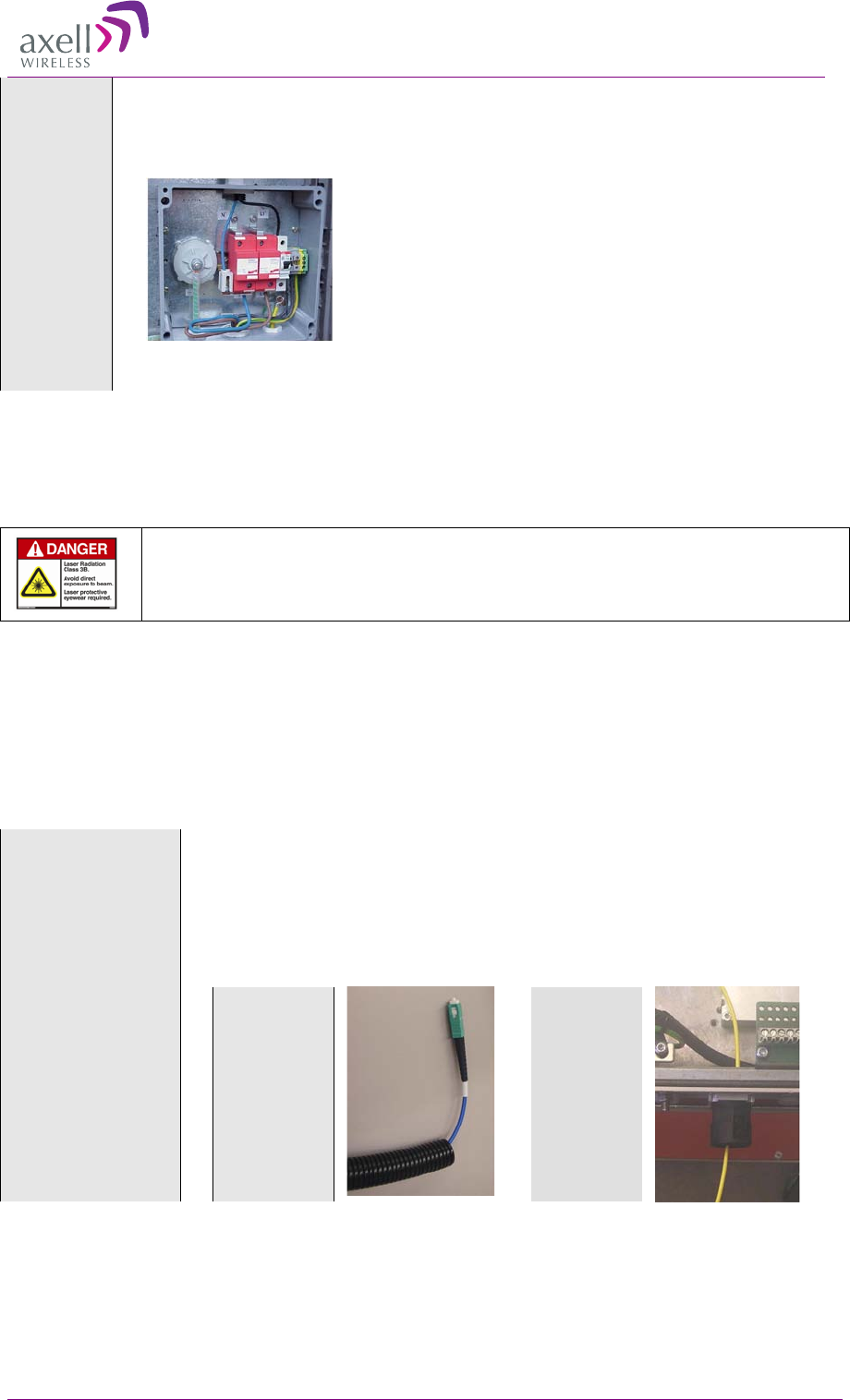
The primary protective device is part of the site installation and is not supplied by Axell
Wireless. Coaxial lightning protection is normally one of these three types: Gas capsule,
High-pass and Bandpass.
There also need to be a protective device installed on the power supply cord.
Protective device installed in connection with the power supply
2
2.
.5
5
F
Fi
ib
br
re
e
O
Op
pt
ti
ic
c
C
Co
on
nn
ne
ec
ct
ti
io
on
n
This product is equipped with class 3B lasers, as per definition in EN 60825-1.
Caution!!!
Un-terminated optical receptacles may emit laser radiation.
Do not stare into beam or view with optical instruments.
Use the following over the complete link between the Repeater and OMU:
• Use angled APC connectors at 8deg angle
• APC type ODF connections
• Mono-mode type fibre
Select fibre
Recommended fibre cable is single mode 9/125.
Connect the fibre
The casing of the repeater is equipped with an inlet. The inlet is designed
to go with a corrugated hose, which is included in the shipment.
The hose, together with the rubber seal meet the protection standard IP65.
1. Run the
fibre
through the
hose
2. Run the
fibre
through
the inlet in
the
repeater
AXELL MBF MULI-BAND FIBER REPEATER
PRODUCT DESCRIPTION AND USER’S MANUAL
© Axell Wireless Ltd 11
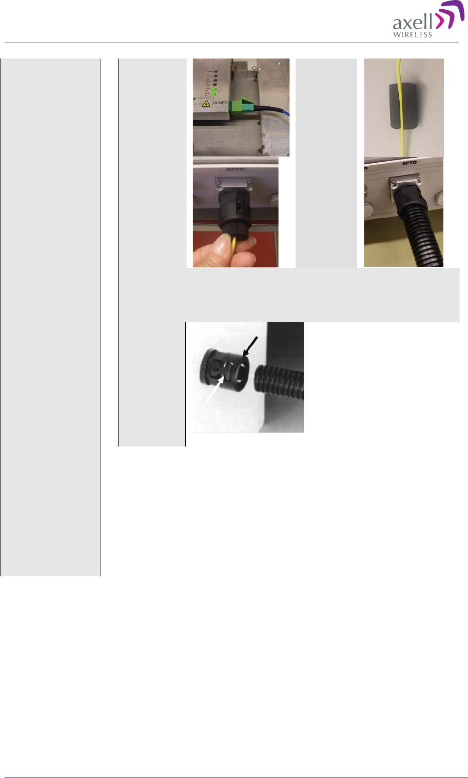
3. Connect
the fibre to
the Fibre
Optic
Converter
inside the
repeater
4. Place
the fibre in
the rubber
seal
5. Adjust
the fibre
length
inside the
repeater and
insert the
seal into the
inlet
6. Attach
the hose to
the inlet
Note!
Make sure the fibre is not bent too sharply inside the repeater.
There is room under the optic module to allow for some slack of the
fibre.
Note!
To
insert and
extract the
hose from
the inlet
press the
side levers.
Make necessary
measurements
Make necessary measurements to ensure a correct installation.
When the cable has been installed, the quality of the optical path should be
checked for optical path loss and magnitude and location of any
reflections. This can be done with an Optical Time Domain Reflectometer
(OTDR). The total return loss should be > 45 dB.
Optical reflections can degrade the noise and linearity of a fibre optic link.
In particular, reflections that reach the laser can be a problem. Keep all
discrete reflections to > 60 dB. The SC/APC connectors are polished to a
return loss >60 dB.
AXELL MBF MULI-BAND FIBRE REPEATER
PRODUCT DESCRIPTION AND USER’S MANUAL
12 © Axell Wireless Ltd
Attach the fibre to
the fibre optic
converter inside the
repeater.
Note!
Clean the fibre connector before it is connected, see instruction
below.
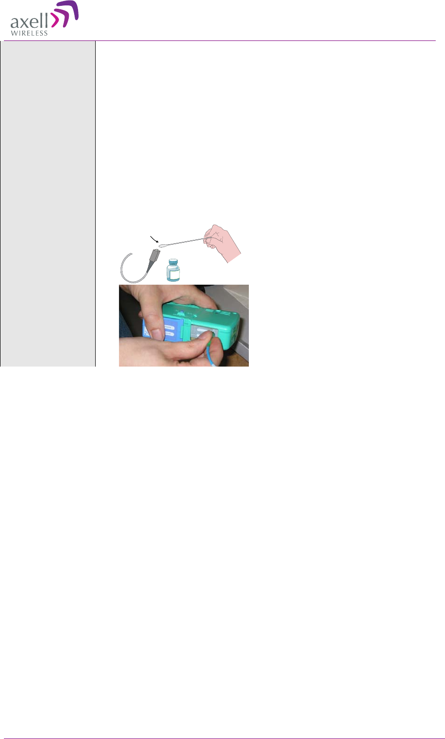
2.5.1 Cleaning Optical Connectors
Optical reflections from a discontinuity such as a poor connector interface
appear on an RF spectrum analyzer trace as stable variations in the noise
floor amplitude that are periodic with RF frequency. If the reflection is bad
enough, it could impact the system performance. By far, the most common
cause for a large discrete reflection is a dirty optical connector. A bit of
dust or oil from a finger can easily interfere with, or block this light.
Fortunately, it is very easy to clean the connector.
Be sure to use the correct procedure for the given connector. When
disconnected, cap the FC/APC connector to keep it clean and prevent
scratching the tip of the ferrule.
Alternative 1
Swipe the tip of the ferule 2-3 times
with a cotton swab soaked in
alcohol. Let it air dry.
Alternative 2
Use a product specially designed for
the purpose.
AXELL MBF MULI-BAND FIBER REPEATER
PRODUCT DESCRIPTION AND USER’S MANUAL
© Axell Wireless Ltd 13
2
2.
.6
6
E
Ex
xt
te
er
rn
na
al
l
A
Al
la
ar
rm
m
a
an
nd
d
R
Re
el
la
ay
y
C
Co
on
nn
ne
ec
ct
ti
io
on
ns
s
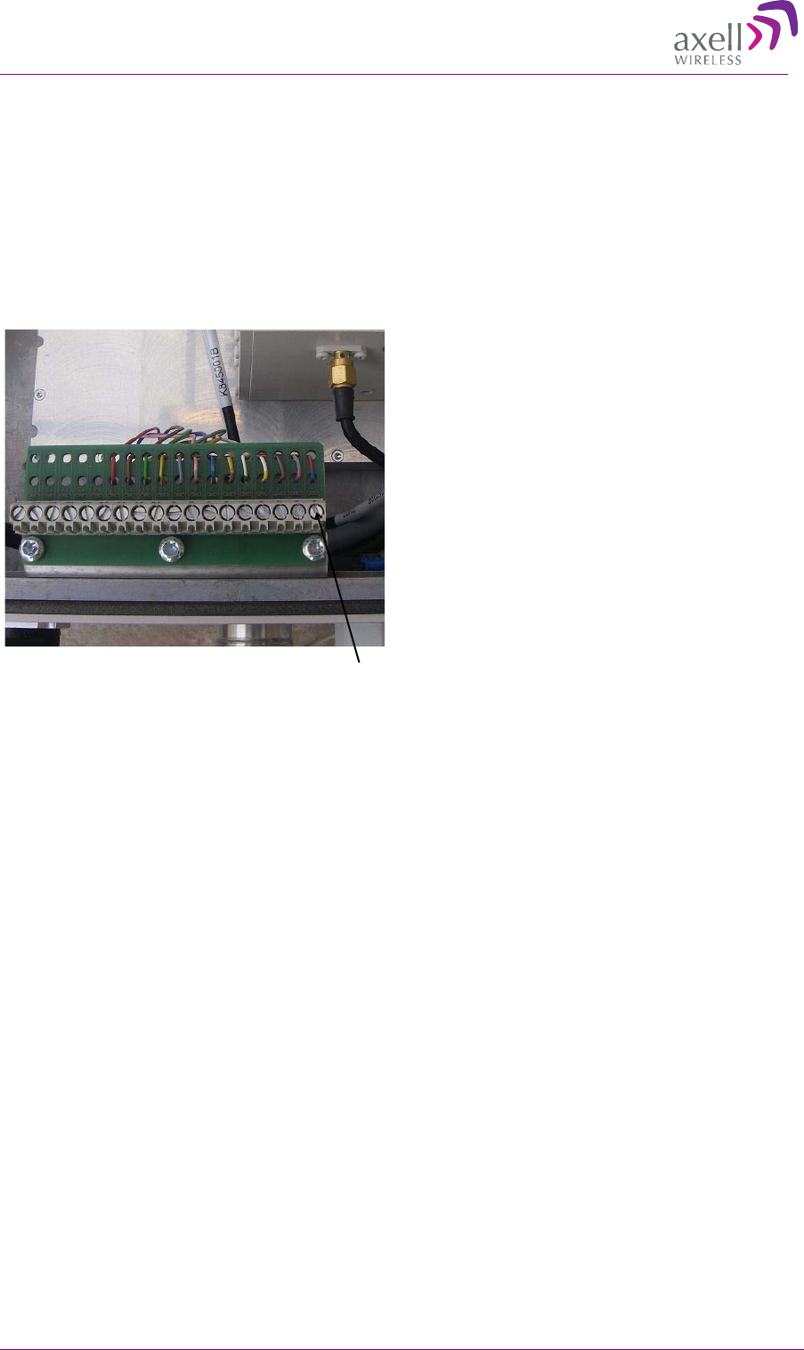
The repeater is equipped with an external alarm interface card. The connector plinth for the external
alarms is located at the bottom of the repeater.
The strain relief fitting in is a Pg 13.5 suitable for a 6-12 mm cable diameter.
Connect the alarm cords to the plinth according to the pin layout below (in the standard version pins
14 – 18 are not used).
2.6.1.1 External Alarm
• Four external alarm sources can be connected to the repeater.
• Alarm operating voltage: between 12 and 24VDC.
• Alarm polarity can be configured:
• Active-low - when there is no voltage the alarm indicator will turn red
• Active-high - an applied voltage of between 12 and 24 V will cause the external alarm
indicator to turn red.
• The repeater can supply +15 VDC to an external alarm source through pin 9 and 10. The
maximum allowed load is 100mA.
2.6.1.2 Relay
• Relay (pin 11 and 12) can be connected to an external device to indicate an alarm.
• Can be configured to trigger on any number of internal and external alarms. The maximum
current that can be supplied is 100mA.
1External alarm 1A
2External alarm 1B
3External alarm 2A
4External alarm 2B
5External alarm 3A
6External alarm 3B
7External alarm 4A
8External alarm 4B
9Alarm +15V
10 Alarm 0V
11 Relay Output 1A
12 Relay Output 1B
13 GND
14 NC
15 NC
16 NC
17 NC
18 NC
Pin # Signal
Pin 1
AXELL MBF MULI-BAND FIBRE REPEATER
PRODUCT DESCRIPTION AND USER’S MANUAL
14 © Axell Wireless Ltd
2
2.
.7
7
P
Po
ow
we
er
r
a
an
nd
d
B
Ba
ac
ck
ku
up
p
B
Ba
at
tt
te
er
ry
y
Caution!
Make sure the antenna cables or 50 ohm terminations are connected to the repeater’s antenna
connectors before the repeater is turned on.
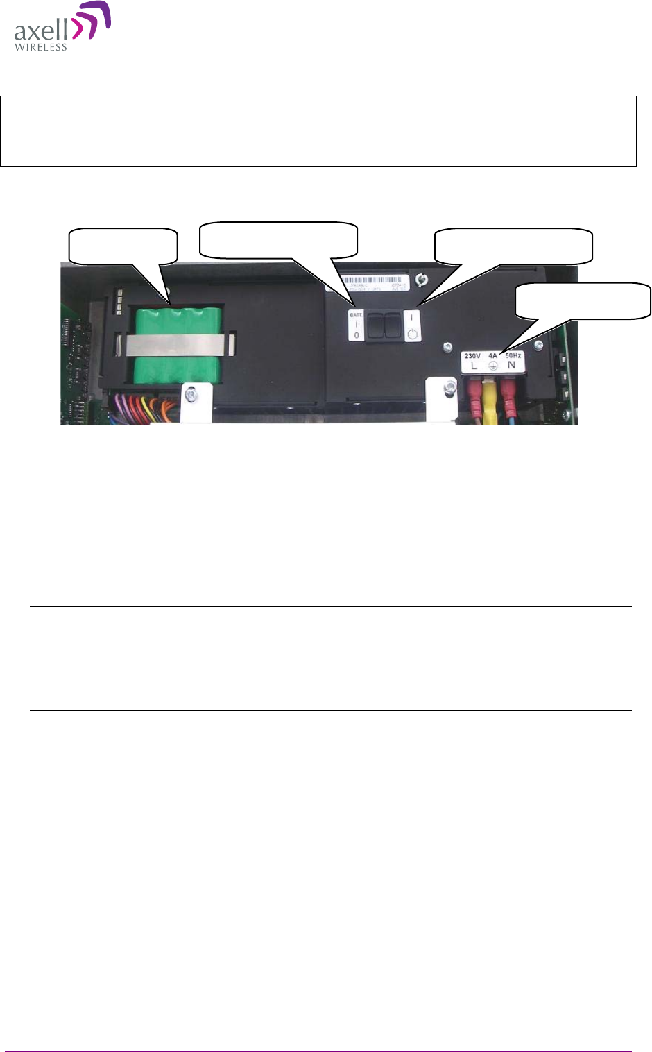
The image below shows the location of the various power elements. These are described in detail in
the following sections.
2-2 Power Elements Inside Repeater
2.7.1 Connecting the Power Source
• Power Source: 230 VAC 50 Hz, 115 VAC 60 Hz or -48 VDC
• The -48VDC version of the power supply is designed to turn off if the supply voltage falls below
-36V (±1V). It will turn on again as the supply voltage reaches -43V (± 1V).
• The power supply has a switch which allows it to be set in “on” position or in “stand by”.
Note!
A. In the stand by position the repeater is still connected to the power supply but not
operational.
B. On repeaters mounted in an extended box with two power supplies, both power supplies
needs to be switched on.
110/230 V AC power
connections
Power ON/Standby
switch
Backup battery
pack
Battery (BATT) ON/OFF
switch
AXELL MBF MULI-BAND FIBER REPEATER
PRODUCT DESCRIPTION AND USER’S MANUAL
© Axell Wireless Ltd 15
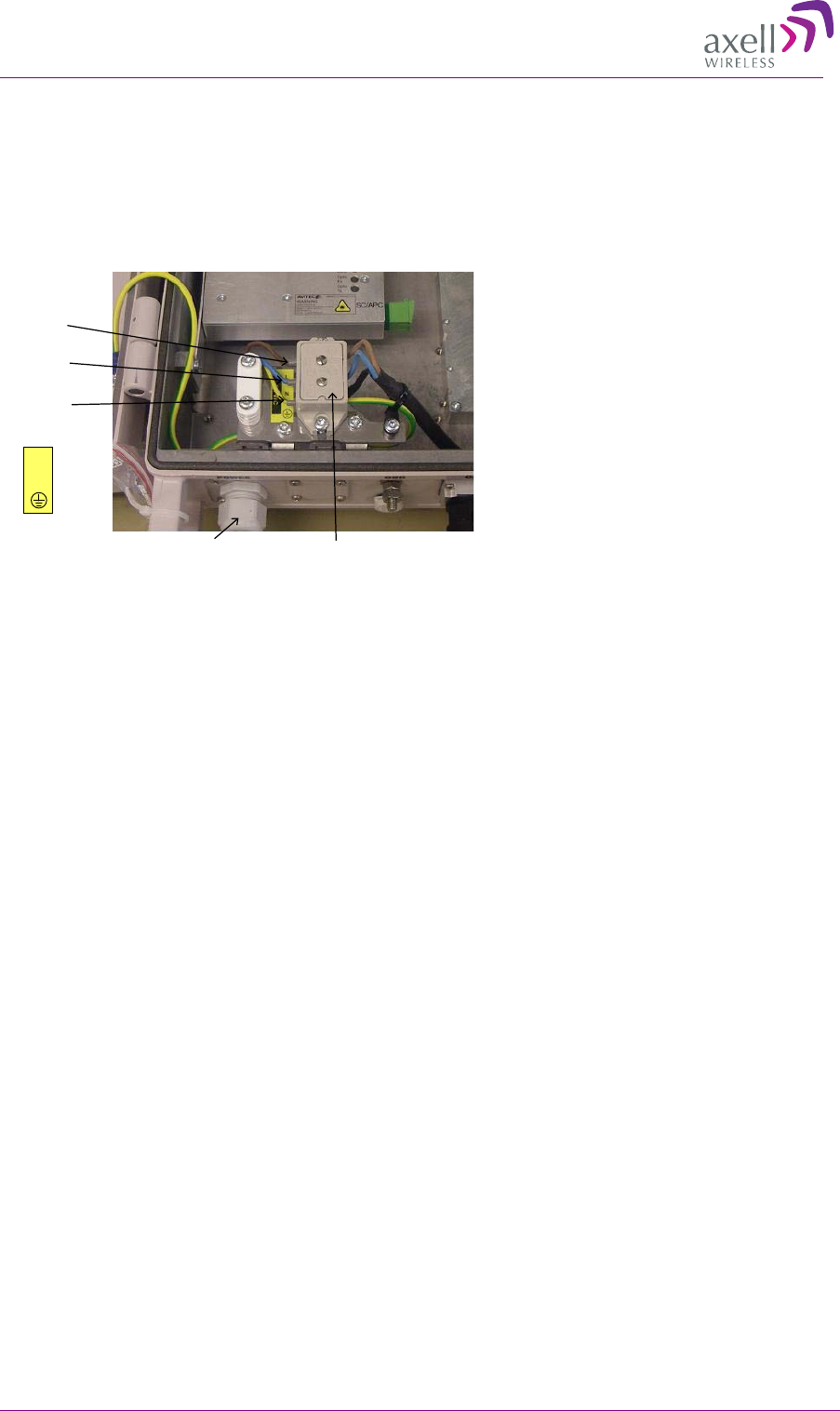
2.7.2 230 VAC Power Source
Connect the power cable to the plinth as show below:
• Phase linked to the brown cable
• Neutral linked to the blue
• Ground to the yellow/green. See illustration below.
Connection Plinth
Phase
/Live
Neutral
Ground
L
N
Strain Relief Fitting
AXELL MBF MULI-BAND FIBRE REPEATER
PRODUCT DESCRIPTION AND USER’S MANUAL
16 © Axell Wireless Ltd
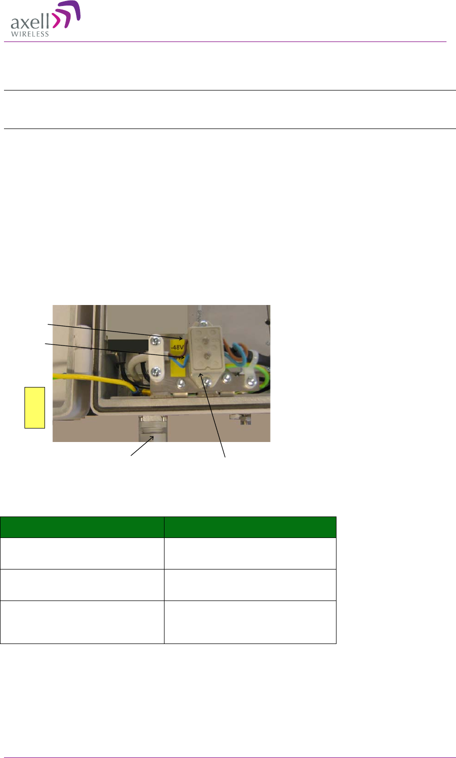
2.7.3 -48V Power Source Connection
Note:The -48VDC version of the power supply is designed to turn off if the supply voltage falls below
-36V (
±
1V), not to drain the feeding battery. It will turn on again as the supply voltage reaches -43V
(
±
1V).
-48V power supply requirements
The 48VDC power supply must comply with SELV requirements, as defined in EN60950, which
implies double isolation. The output power needs to be 48VDC +25%/-15%. The maximum input
current is 8A.
Connect the power cable to the plinth with:
• Negative (-48V) to the uppermost connection
• Positive (0V) to the lower connection.
• Do NOT connect the middle connection.
Recommended cable areas for 48VDC
Distance Cable Area
0 - 10 meters between repeater and
power supply 2,5 mm²
10 – 50 meters between repeater and
power supply 4 mm²
Over 50 meters between repeater and
power supply Recommendation is to reconfigure the
installation, or to make special
arrangements to increase cable area
Connection Plinth
Negative
Positive
-48V
0V
Strain Relief Fitting
AXELL MBF MULI-BAND FIBER REPEATER
PRODUCT DESCRIPTION AND USER’S MANUAL
© Axell Wireless Ltd 17
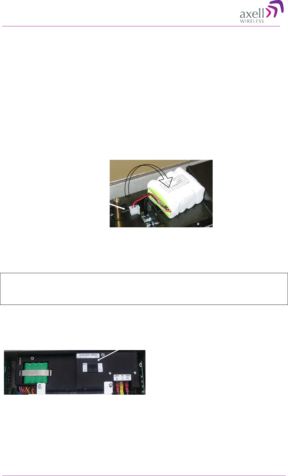
2.7.4 Backup Battery
• On the Power Supply unit a rechargeable battery pack in mounted. This part also includes
charging and supervision electronics.
• The backup battery will provide the Control Module and modem with enough capacity to send an
alarm in case of input power failure.
• The battery can be switched on and off. The switch is placed adjacent to the main power switch
on the power supply.
• At delivery the back-up battery is connected.
• The battery is replaced by lifting the battery pack out of the crate and disconnecting the cable.
2
2.
.8
8
P
Po
ow
we
er
r
O
ON
N
2.8.1 Switching Power ON
Caution!
Make sure the antenna cables or 50 ohm terminations are connected to the repeater’s antenna
connectors before the repeater is turned on.
The rightmost switch is the one that switches the main power. The leftmost is for turning the battery
on/off.
Note! The power switch has two positions; “on” and “stand by”. In the stand by position the repeater
is still connected to the power supply but not operational.
Connector
Switch the repeater on by using the power switches on the power supply.
Note! See caution above!
There are two switches. One is for the battery and one is for the power
Power Switch

AXELL MBF MULI-BAND FIBRE REPEATER
PRODUCT DESCRIPTION AND USER’S MANUAL
18 © Axell Wireless Ltd
Note! On repeaters mounted in an extended box with two power supplies, both power supplies needs
to be switched on.
2.8.2 Verifying LEDs
Verify the LEDs from the following modules are indicating correct operation ( 5.1):
• Control module
• F/O converter
• Power supply modules
2
2.
.9
9
C
Cl
lo
os
si
in
ng
g
a
an
nd
d
S
Se
ec
cu
ur
ri
in
ng
g
t
th
he
e
R
Re
ep
pe
ea
at
te
er
r
Close lid, tighten screws and lock repeater, or continue with the next section: Start-up the Repeater.
Note! The two screws must be fully tightened. Failure to do so may affect the IP65 compliancy and
therefore any warranty.

AXELL MBF MULI-BAND FIBER REPEATER
PRODUCT DESCRIPTION AND USER’S MANUAL
© Axell Wireless Ltd 19
3
3
C
Co
om
mm
mi
is
ss
si
io
on
ni
in
ng
g
A
Ad
dv
vi
ic
ce
e
To set the proper operating RF levels on the repeaters in the MBF family during commissioning there
are six steps to be carried out for each band of operation.
Set OMU DL attenuation to adjust the RF level from the BTS to suit the fibre optic converter in
the OMU (UFO-M)
Run the OLA (Optical Link Adjustment) command for each band to correct for DL optical fibre
loss
Set the DL attenuation in the repeater to adjust gain following fibre optic converter in the
repeater (UFO-S)
Set the UL attenuation in the repeater to adjust gain before the fibre optic converter in the
repeater (UFO-S)
Run the OLA (Optical Link Adjustment) command for each band to correct for DL optical fibre
loss
Set OMU UL attenuation to adjust the OMU output level to suit the BTS
3
3.
.1
1
S
Si
ig
gn
na
al
l
D
Di
ia
ag
gr
ra
am
ms
s
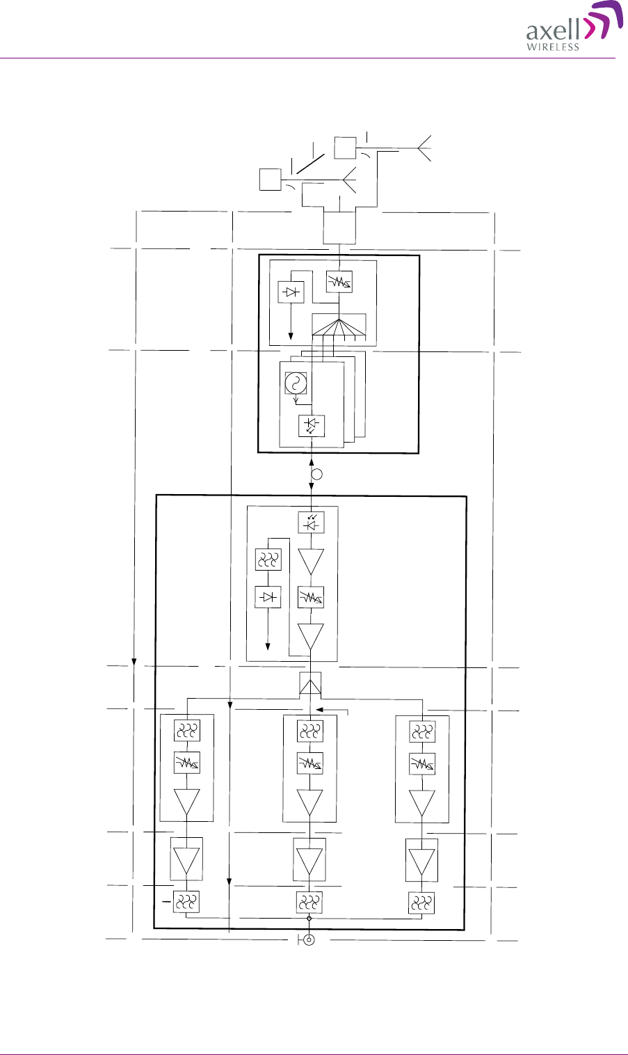
In the downlink the signal from the OMU enters the fibre optic converter in the repeater that
translates the optical signal to RF. The signal is fed to the Radio Modules. The signals are amplified
in the Radio Modules and further in the separate MCPAs. It is then fed to the combined duplex filter
and out on the server port to the antenna.
In the uplink the signal is amplified in the Radio Modules and translated to an optical signal and fed
back to the OMU.
A tri band repeater works in a corresponding way.
3-1. Single band repeater for E-GSM
Duplex
Filter
RF
O
Optical
In/Out
Downlink
RF in/out
Fiber Optic
Converter
Radio Module
GSM
MCPA GSM
Uplink
~
~
~
~
~
~
~
~
~
~
~
~

AXELL MBF MULI-BAND FIBRE REPEATER
PRODUCT DESCRIPTION AND USER’S MANUAL
20 © Axell Wireless Ltd
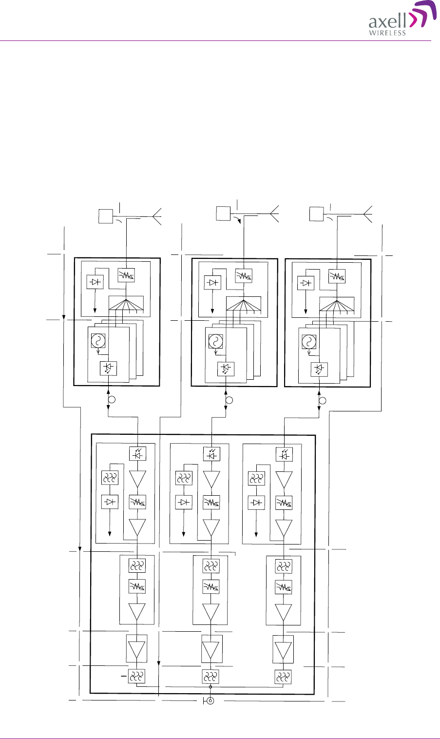
3-2. Dual band repeater for E-GSM and UMTS
3
3.
.2
2
O
OM
MU
U
P
Po
oi
in
nt
t
o
of
f
I
In
nt
te
er
rf
fa
ac
ce
e
(
(P
PO
OI
I)
)
The OMU will usually be fed from the donor BTS via an attenuator or coupling network. The
electrical configuration of this OMU Point of Interface (POI) will be system specific depending on
the presentation of the BTS RF ports, the power class of the BTS and whether the BTS itself provides
coverage via antennas/radiating cable infrastructure or if coverage is only via the MBF repeaters.
The important consideration for commissioning is that the correct attenuation exists between BTS
and OMU in order that
input power limits of OMU ports are not exceeded
operating levels can be brought into the correct range using the OMU internal attenuators
isolation is preserved between ports and bands
OMU damage levels are 10dBm RF in to the fibre optic converter.
For some systems the commissioning adjustments may be completely independent (e.g. an MBF Tri
Band repeater fed by separate OMUs, one per frequency band). For other systems (e.g. an MBF Tri
Band repeater fed a by a single OMU carrying all three bands) one adjustment may affect all bands
simultaneously. In such cases certain commissioning actions e.g. optical link adjustment only need to
be carried out once for all bands but the POI must include some means to level the different
frequency bands at the OMU interface ports.
3
3.
.3
3
D
Do
ow
wn
nl
li
in
nk
k
P
PO
OI
I
/
/
O
OM
MU
U
D
DL
L
A
At
tt
te
en
nu
ua
at
to
or
r
A
Ad
dj
ju
us
st
tm
me
en
nt
t
The critical aspect for the correct system operating level is the composite power presented at the
input of the fibre optic converter in the OMU (UFO-M). The illustration below shows the simplest
possible arrangement for a single Tri Band repeater fed by three BTSs - one per band. It is assumed
that the BTS for GSM900 and GSM1800 produce two carriers each of +43dBm and that the UMTS
BTS produces a single carrier of +43dBm.
MCPA UMTS
2 x
Duplex
Filter
RF
O
Optical
In/Out
Downlink
Uplink
RF in/out
Fiber Optic
Converter
Radio Module
UMTS
Radio Module
GSM
MCPA GSM
Downlink
Uplink
~
~
~
~
~
~
~
~
~
~
~
~
~
~
~
~
~
~
~
~
~
~
~
~
AXELL MBF MULI-BAND FIBER REPEATER
PRODUCT DESCRIPTION AND USER’S MANUAL
© Axell Wireless Ltd 21
The correct interface level at the optical fibre converter is -5dBm/carrier in 900MHz and -
7dBm/carrier in both GSM1800 and UMTS bands. An attenuation of 48dB in 900MHz and 50dB in
1800/UMTS is therefore required between them.
MBF-T-9-18-22
OMU #1
UFOM #3
UFOM #2
RB2200
BS
BS
UMTS
RB900
-17dB
-19dB
MCPA UMTS
+40dB
+24dB-1dB
+18dB
Atten=1
Atten=4
(Max Gain=25dB)
+40dB
MCPA GSM900
-1.5dB
-17dB
-1dB
-1dB-17dB
-30dB
-30dB
UMTS:
+43dBm
GSM900:
2x+43dBm
0..10dB
optical
2x+12dBm
(IL=16dB)
(IL=14dB)
(Max Gain=22dB)
2x-5dBm
2x-4dBm2x+35.5dBm2x+34dBm
+12dBm-7dBm
0dBm+40dBm+39dBm
RB1800MCPA 1800
Atten=5
+40dB
+20dB-1.5dB
2x+35.5dBm
2x-4dBm
-19dB
-1dB
(IL=16dB)
-17dB
GSM1800:
2x+43dBm
2x-7dBm
2x-24dBm
2x-24dBm
2x+12dBm
UFOSAtten: 0-20dB
PD
Pilot Level
UFOS
Atten=3
Det Pwr
UFOM #1
LD
Pilot tone
ANT
UFOSAtten: 0-20dB
PD
Pilot Level
UFOSAtten: 0-20dB
PD
Pilot Level
2x-22dBm
(Max Gain=25dB)
-24dBm
OMU #2
UFOM #3
UFOM #2
0..10dB
optical
UFOS
Atten=3
Det Pwr
UFOM #1
LD
Pilot tone
OMU #3
UFOM #3
UFOM #2
0..10dB
optical
UFOS
Atten=3
Det Pwr
UFOM #1
LD
Pilot tone
BS
GSM1800
-30dB

AXELL MBF MULI-BAND FIBRE REPEATER
PRODUCT DESCRIPTION AND USER’S MANUAL
22 © Axell Wireless Ltd
It must also be kept in mind that the OMU might have separated input/output ports for each band
(UL/DL) while the interface with the BTS may well be duplex. In that case some duplexing network
must be provided to allow these to be brought together. If there is more than one operator’s BTS per
band the loss of any combining network and any equipment room cabling also becomes part of the
overall attenuation required to reach the correct interface level in each frequency band.
The illustration on the next page shows a more complicated arrangement where the same three BTSs
feed multiple MBF repeaters (up to 6 is possible using the standard splitter card which fits the OMU
rack). In this case an OMU per frequency band is shown. The internal splitter has an insertion loss of
14 or 16dB depending on frequency band. This loss is again a contribution to the overall attenuation
which must be provided between BTS and the input ports of the UFO-M for the correct operational
levels to be achieved.
The interface levels must be modified to maintain the same composite power if a greater number of
carriers is to be applied from the BTS.
The DL POI / OMU Adjustment must be made considering the fully loaded condition – e.g. a BTS
capacity of 8 carriers must include a back off of 6dB compared to the 2 carrier level and -
11dBm/carrier is then the correct UFO-M drive level for GSM 900. The same rule for back off
applies in other bands.
Note that a UMTS BTS at idle (no traffic) will be radiating only a pilot – approx -10dB compared to
the average power when it is in traffic. See also section about UMTS Signal Measurement below.
3
3.
.4
4
R
Re
ep
pe
ea
at
te
er
r
D
Do
ow
wn
nl
li
in
nk
k
O
Op
pt
ti
ic
ca
al
l
L
Li
in
nk
k
A
Ad
dj
ju
us
st
tm
me
en
nt
t
(
(O
OL
LA
A)
)
The optical link between the UFO-M of the OMU and the UFO-S in the repeater is equipped with a
calibrated pilot tone transmitter/receiver which enables compensation for the loss of the optical fibre
plant between them.
The OLA procedure requires a computer running Axell RMC software and an RS232 connection to
the LMT Port of the repeater controller.
Start the RMC and login to the repeater as described in the appropriate section of the handbook. Click
on the Actions tab on top of the RMC screen. A drop down list will appear where a command will be
found to execute the optical link adjustment for each UFO-S module that is fitted to the repeater.
Click the command for the desired optical link and following a short delay (2-3 secs) an information
screen will be shown describing the result of the automatic setup process.
This procedure is described in the OMU Manual section 4.10.
3
3.
.5
5
D
Do
ow
wn
nl
li
in
nk
k
R
Re
ep
pe
ea
at
te
er
r
G
Ga
ai
in
n
A
Ad
dj
ju
us
st
tm
me
en
nt
t
When the DL POI levels and the repeater optical links have both been set up as described in the
foregoing the MBF repeater set at maximum gain should produce a composite signal level at the
output connector of +37dBm for GSM900 and 1800 and +39dBm for UMTS.
The RMC provides sub screens for each band where the downlink power from UFO-S optical
receiver /input to the DL radio board and the composite output power level from the MCPA can be
viewed.
The power amplifier for each frequency band can be enabled /disabled and the preset DL attenuation
in the radio board for each band can be adjusted. A saturation status indicator (red/green) shows
whether the radio board ALC is in operation. This indicator should be green. A red indication
indicates overdrive the cause of which should be investigated and rectified.
In each band the DL output power per carrier should be measured using a spectrum analyzer.
Allowing for the maximum DL carrier quantity in each band the composite level per band under full
loading should be calculated to ensure it does not exceed the rated maximum otherwise ALC will be
in operation when traffic levels are high. See also section about UMTS Signal Measurement below.
AXELL MBF MULI-BAND FIBER REPEATER
PRODUCT DESCRIPTION AND USER’S MANUAL
© Axell Wireless Ltd 23
OMU
MBF-T-9-18-22
UFOM #3
UFOM #2
RB2200
BS
BS
GSM900
UMTS
RB900
-17dB
-19dB-4dB
MCPA UMTS
+40dB
+28dB-1dB
+22dB
Atten=1
Atten=4
(Max Gain=29dB)
+40dB
MCPA GSM900
+4dB-1.5dB
Split
-17dB
-1dB
-1dB-17dB
-30dB
-30dB
UMTS:
+43dBm
GSM900:
2x+43dBm
0..10dB
optical
2x+12dBm
(IL=16dB)
(IL=14dB)(Max Gain=26dB)
2x-5dBm2x-22dBm2x-26dBm2x-4dBm2x+35.5dBm2x+34dBm
+12dBm-7dBm-24dBm-28dBm0dBm+40dBm+39dBm
RB1800MCPA 1800
Atten=5
+40dB
+24dB-1.5dB
-4dB
2x+35.5dBm
2x-4dBm
-19dB
-1dB
(IL=16dB)
-17dB
GSM1800:
2x+43dBm
2x-7dBm2x-24dBm
2x-28dBm
(Max Gain=29dB)
2x+12dBm
UFOSAtten: 0-20dB
PD
Pilot Level
UFOS
Atten=3
Det Pwr
UFOM #1
LD
Pilot tone
Comb
Netw
ANT

AXELL MBF MULI-BAND FIBRE REPEATER
PRODUCT DESCRIPTION AND USER’S MANUAL
24 © Axell Wireless Ltd
3
3.
.6
6
U
UM
MT
TS
S
S
Si
ig
gn
na
al
l
M
Me
ea
as
su
ur
re
em
me
en
nt
t
The UMTS signal carries wideband and complex modulation and its properties vary depending on the
level of traffic carried.
3.6.1 Bandwidth
The first issue is the wideband nature of the signal. It occupies around 3.8MHz and measurements
through a narrower filter will reduce the apparent power level since only a portion of the signal
reaches the detector in the test equipment.
Equipment that includes a UMTS/3G measurement personality simplifies the task considerably.
Usually a stored configuration for power measurement will integrate many samples taken using a
narrower filter to display the correct power level for the bandwidth of the signal. Settings can easily
become corrupted however leading to erroneous results. In such cases following the manufacturers
instructions in detail is advised.
Measuring with a simple spectrum analyzer must use a wider resolution bandwidth than 3.8MHz or
else a bandwidth correction factor has to be applied to the observed result. E.g. if measuring with a
300kHz RBW the power level in the centre of the signal would appear to be around 11dB lower than
actual (10Log 3.84/0.3).
3.6.2 Traffic
A further complication is that the power level of a UMTS signal depends on the traffic level being
carried. UMTS carrier power is usually quoted as average values e.g. a 5Watt or 37dBm signal can
contain peaks up to 10dB greater when traffic is high. An idling base station carrying no traffic
radiates only a Pilot in which case the power observed is around 10dB below the average value with
traffic.
Advanced test equipment that can measure the different code power components in the UMTS signal
avoids this problem but more often in the field repeater commissioning must be done when only
simple test equipment is available. This leads to the need to know and allow for the state of traffic
when making repeater setup and diagnostic measurements. It is obvious that adjusting a repeater to
maximum rated output power by using BTSs that are idling radiating only the pilot will lead to
overloading when they are in traffic.

AXELL MBF MULI-BAND FIBER REPEATER
PRODUCT DESCRIPTION AND USER’S MANUAL
© Axell Wireless Ltd 25
4
4
S
Se
et
tu
up
p
AXELL MBF MULI-BAND FIBRE REPEATER
PRODUCT DESCRIPTION AND USER’S MANUAL
26 © Axell Wireless Ltd
4
4.
.1
1
O
Op
pe
en
n
a
a
L
Lo
oc
ca
al
l
S
Se
es
ss
si
io
on
n
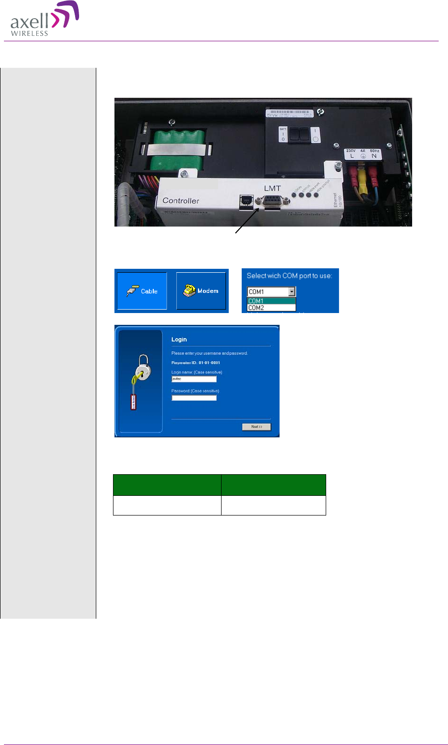
Connect to the LMT
port
Connect the computer to the LMT port via a DB9 male connector with serial RS232
interface.
The communication parameters are set automatically by the RMC
Select “Cable”
connection and
communication
port
Enter user name
and password
Several users at a time can be logged on to a Repeater, for instance one
locally via the RS232 interface and one remotely via modem or Ethernet.
There is one default user name and password defined for the repeater..
User Name Password
avitec AvitecPasswd
Note!
Both the user name and the password are case sensitive.
Note!
Do not use the number pad when entering numbers.
Note!
Failed login attempts are logged. Default maximum number is 8. It is
decremented by one every hour, which means that it takes one hour after the
last failed attempt before a new try can be made.
LMT Port
AXELL MBF MULI-BAND FIBER REPEATER
PRODUCT DESCRIPTION AND USER’S MANUAL
© Axell Wireless Ltd 27
The Console mode
view appears
The console mode displays a large number of repeater parameters and
contains a number of console pages. It adjusts its user interface to adapt
to the features of the connected repeater.
4
4.
.2
2
S
Se
et
t
R
Re
ep
pe
ea
at
te
er
r
N
Na
am
me
e
(
(T
TA
AG
G)
)
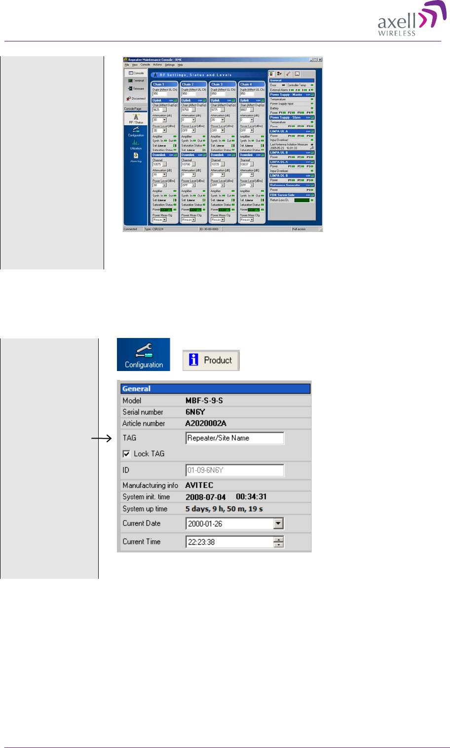
The TAG can be chosen freely to give the repeater a name that is linked to the location, the site name,
etc. The TAG may contain up to 30 characters including spaces.
Select
“Configuration” and
“Product”
Insert the repeater’s
name (TAG) in this
box.
Note! Do not assign an ID. The AEM will do this automatically when the
repeater is integrated in the AEM.
AXELL MBF MULI-BAND FIBRE REPEATER
PRODUCT DESCRIPTION AND USER’S MANUAL
28 © Axell Wireless Ltd
4
4.
.3
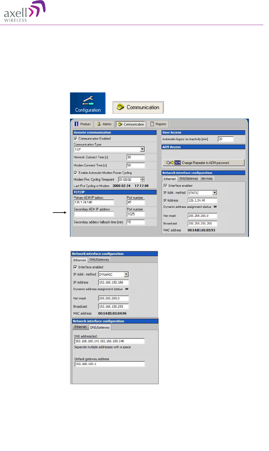
3
T
TC
CP
P/
/I
IP
P
a
an
nd
d
E
Et
th
he
er
rn
ne
et
t
C
Co
om
mm
mu
un
ni
ic
ca
at
ti
io
on
n
A TCP/IP communication is run over a company’s network. Therefore each company needs to define
the details regarding the configuration, IP addresses, etc. For more information please refer to
Common Commands and Attributes, section 13 Network Configurations.
Select
“Configuration” and
“Communication”
Set IP address and
other relevant
information here
In these screens the
Ethernet and/or DNS
Gateway parameters
can be set
AXELL MBF MULI-BAND FIBER REPEATER
PRODUCT DESCRIPTION AND USER’S MANUAL
© Axell Wireless Ltd 29
4
4.
.4
4
S
Se
et
t-
-u
up
p
R
RF
F
C
Co
on
nf
fi
ig
gu
ur
ra
at
ti
io
on
n
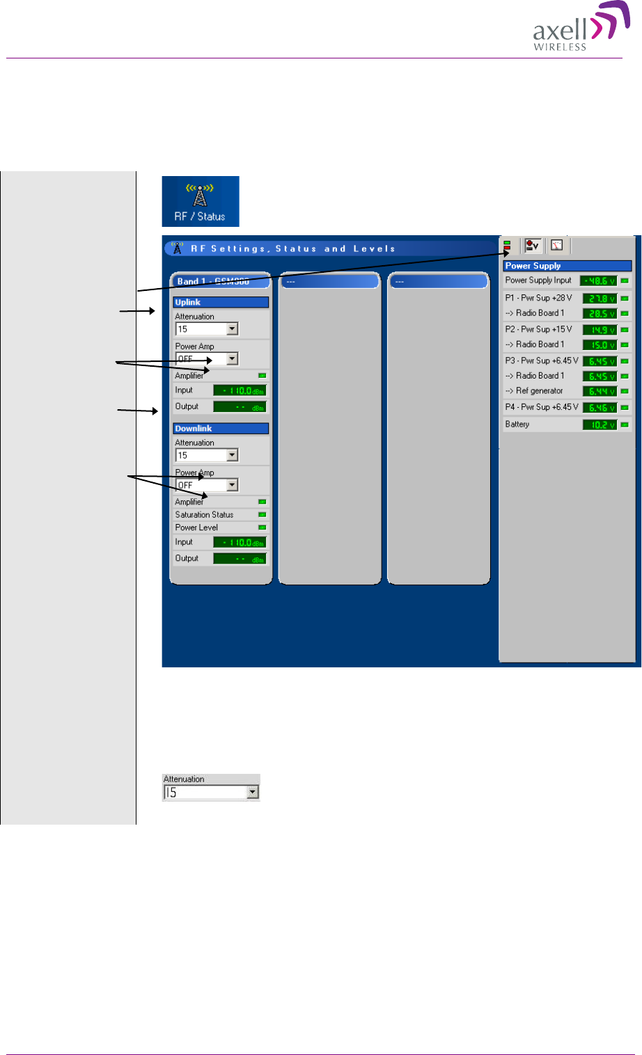
Configuration of the repeater amplification can be made locally. If the repeater is connected to an
OMU the configuration can also be made via this OMU. See OMU User’s Manual.
Note! This is an example from a single band repeater. Other repeaters will have similar features.
Ensure online
communication
with the repeater
Select “RF/Status” window
Alarms and general
information
Uplink attenuation
Uplink input and
output power
Downlink
attenuation
Downlink input
and output power
This shows a single band repeater with no RF signals
Check that the fibre
is OK
Make sure there are no alarms relating to the fibre.
Set attenuation level
in uplink and
downlink to a
maximum
Choose the maximum attenuation value from the drop down menu.
AXELL MBF MULI-BAND FIBRE REPEATER
PRODUCT DESCRIPTION AND USER’S MANUAL
30 © Axell Wireless Ltd
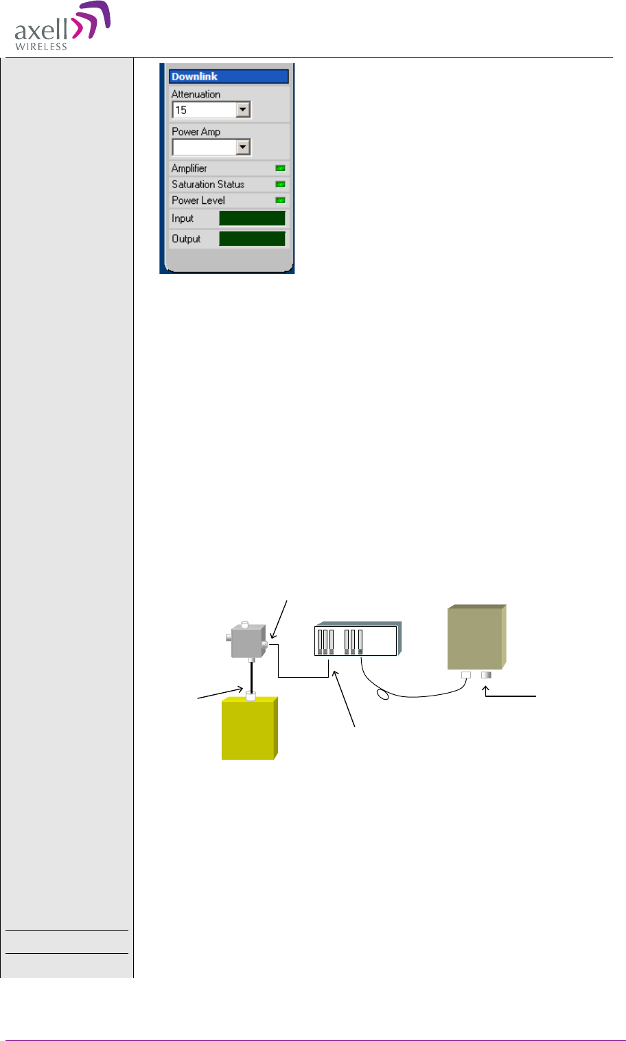
Configure the
downlink
Lower the attenuation level step by step until the desired output power level is
reached. In this example +33 dBm. Zero attenuation is the same as maximum gain.
Note! Please also consult the OMU User’s Manual.
Initiate a fibre loss
elimination
This is done from the OMU by sending a pilot tone to the repeater and calculating the
loss in the fibre link. This loss is compensated for automatically. The system will
behave as if there is no loss at all in the fibre link.
Configure the
uplink
In the uplink direction the attenuation needs to be set based on a measurement of a
known signal which is transmitted through the repeater and the OMU as well as the
fibre. There are two ways of performing this measurement.
Alternative 1
Use a signal generator to insert a signal of approximately -70dBm into the repeater’s
server antenna port. Measure the signal level on the BTS or on the coupler and adjust
the attenuation so that the total gain in the uplink is close to 0dB. (At 0dB gain the
signal level at the coupler should be -40dBm and on the BTS -70dBm in this
example.)
Alternative 2
Use a signal generator to insert a signal of approximately -70dBm into the repeater’s
server antenna port. Log into the OMU and monitor the uplink via the RMC. This
measurement is not as accurate as alternative 1.
Note! If several repeaters are connected to the same OMU the total gain in each
chain should be slightly lower than 0dB not to insert too much noise into the BTS.
Note!
For in-depth instructions for commissioning of an OMU-Repeater system please
contact your Axell Wireless representative.
ON
-19.0dBm
33dBm
Repeater
Signal
Generator
Fiber -70dBm
BTS
-30dB
Coupler
OMU
-40dBm
-70dBm
Alternative 2: Use the RMC to
measure the uplink at the OMU

AXELL MBF MULI-BAND FIBER REPEATER
PRODUCT DESCRIPTION AND USER’S MANUAL
© Axell Wireless Ltd 31
4
4.
.5
5
F
Fo
or
r
S
St
ta
an
nd
d-
-a
al
lo
on
ne
e
R
Re
ep
pe
ea
at
te
er
rs
s
–
–
M
Mo
od
de
em
m
C
Co
om
mm
mu
un
ni
ic
ca
at
ti
io
on
n
MODEM communication is relevant only for Repeaters installed in stand-alone mode. If the
repeater is fibre fed and is set up as a slave- this section is not relevant since the remote
communication is handled by the node master – in most cases an OMU.
For instructions on modem setup and communication, refer to Chapter Modem Communication.
4
4.
.6
6
A
AE
EM
M
A
Ad
dd
dr
re
es
ss
se
es
s
The Control Module can be configured with two different addresses (telephone numbers) to which
alarms and reports are delivered. In case the repeater cannot deliver alarms and reports to the primary
address, the next call will be made to the secondary address.
A fallback functionality is available, which means that the Control Module falls back to the primary
address after a configurable number of minutes. If this interval is set to 0, the fallback will not be
performed. A user can always force the Control Module to fall back to the primary address.
Note! When the repeater is integrated to the Axell Element Manager system, these addresses are set
by the AEM, why they need not be configured during site installation.
4
4.
.7
7
I
In
nt
te
eg
gr
ra
at
ti
io
on
n
i
in
nt
to
o
t
th
he
e
A
AE
EM
M
When the repeater has been installed at site and the remote communication has been enabled, the
repeater can be integrated to the Axell Element Manager. This is done by the operator of the AEM.
After entering the telephone number to the repeater, the AEM dials up the repeater, downloads all the
repeater parameters and statuses into a database. When all parameters have been downloaded, the
AEM configures the repeater with the telephone number where alarms and reports should be sent,
and optionally with a secondary telephone number where the repeater can dial in case connection to
primary number fails.
When heartbeat reports and alarms are sent from the repeater to the AEM also the latest information
about the status and RF-configuration is included. This means that the AEM operator always has
information about the current status in the AEM database (and do not need to call the repeater to find
this out).
Note! Once the repeater is integrated to the AEM, all changes to the repeater should preferably be
done from the Axell Element Manager in order to ensure that the database always contains correct
information.
AXELL MBF MULI-BAND FIBRE REPEATER
PRODUCT DESCRIPTION AND USER’S MANUAL
32 © Axell Wireless Ltd
5
5
T
Tr
ro
ou
ub
bl
le
es
sh
ho
oo
ot
ti
in
ng
g
5
5.
.1
1
M
Mo
od
du
ul
le
e
L
LE
ED
Ds
s
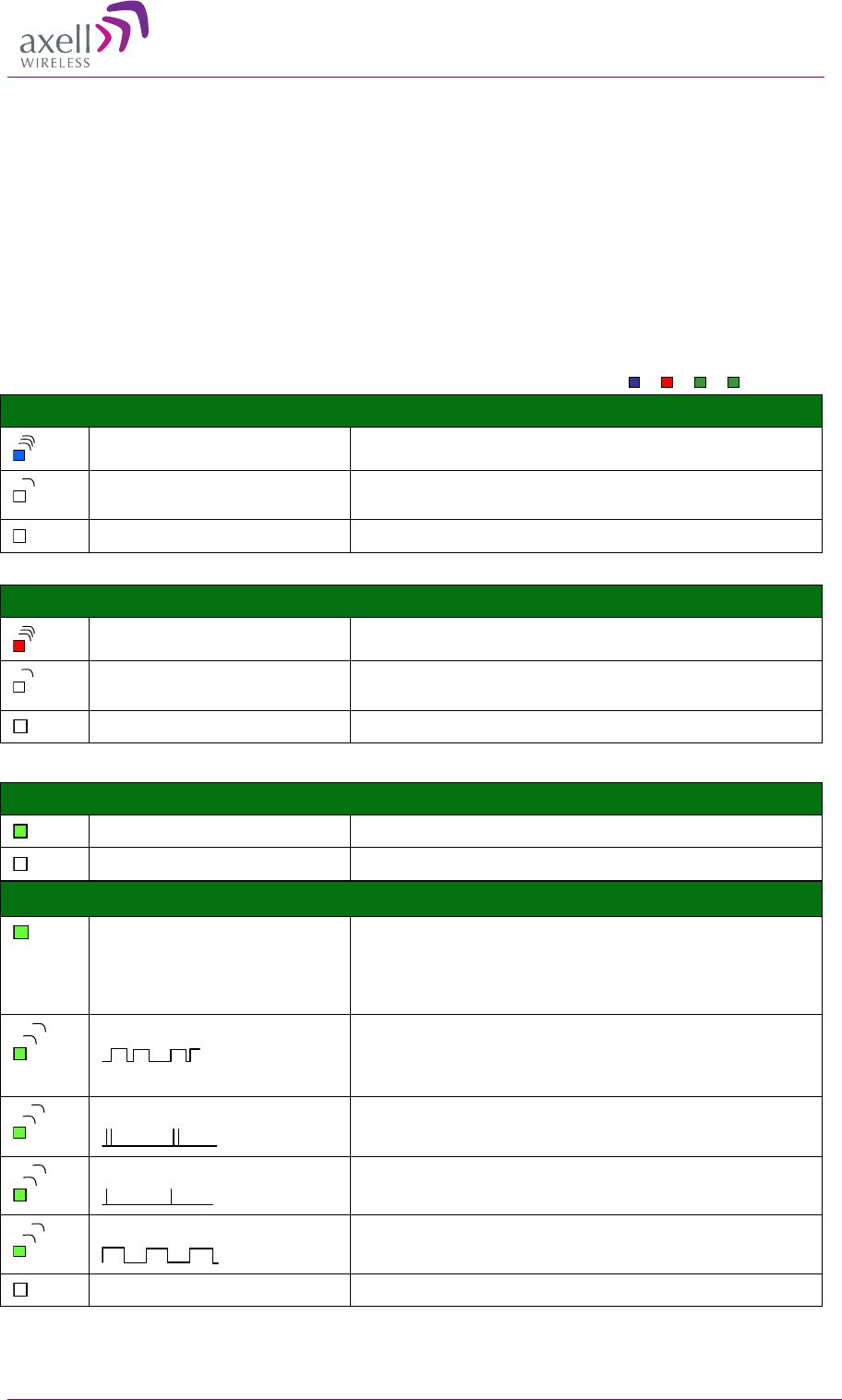
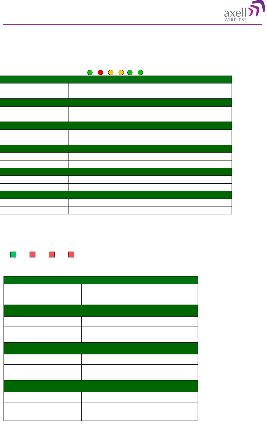
5.1.1 Control Module LEDs
The Control Module has four LEDs which give information regarding
the status of the OMU.
If the OMU is configured for Ethernet communication the two LEDs
Modem Power and Modem Status do not fill any function and can be
disregarded.
Blue LED - Login
Quick flash Control Module switched on, someone logged in locally and/or remotely
Off (except for a quick flash every 10th
second) Control Module switched on, no one logged in
Off (permanent) Control Module switched OFF
Red LED - Status
Quick flash Control Module switched on, one or more errors/alarms detected
Off (except for a quick flash every 10th
second) Control Module switched on, status OK
Off (permanent) Control Module switched off
Green LED – Modem Status
On
Depending on type of call:
Voice call: Connected to remote party
Data call: Connected to remote party or exchange of parameters while
setting up or disconnecting a call
Flashing
(irregular)
Indicates GPSR data transfer. When a GPRS transfer is in progress the LED
goes on within 1 second after data packets were exchanged. Flash duration
in approximately 0.5s.
75ms on/75ms off/75ms on/3s off
One or more GPRS contexts activated
75ms on/3s off
Logged to network (monitoring control channels and user interactions). No
call in progress
600ms on/600ms off
No SIM card inserted, or no PIN entered, or network search in progress, or
ongoing user authentications, or network login in progress
Off Modem is off
Modem Status
Modem Power
Status
Login
Green LED – Modem Power
On Modem Power is on
Off Modem Power is off
AXELL MBF MULI-BAND FIBER REPEATER
PRODUCT DESCRIPTION AND USER’S MANUAL
© Axell Wireless Ltd 33
5.1.2 F/O Converter
There are 6 LEDs on
the module to indicate
the status.
LED 1, Power, Green
On
Unit is powered on
Off
Unit has no power
LED 2, Error, Red
On
Error detected
Off
No error
LED 3, UL Data, Yellow
On
Communication is ongoing in the uplink direction
Off
No communication
LED 4, DL Data, Yellow
On
Communication is ongoing in the downlink direction
Off
No communication
LED 5, Opto Rx, Green
On
Received RF signal on fibre channel is above threshold
Off
Input level below threshold
LED 6, Opto Tx, Green
On
Transmitted RF signal on fibre channel is above threshold
Off
Output level below threshold
5.1.3 Power Supply LEDs
This section provides a detailed description of the LEDs and examples of faults.
LED 1, Input Power, Green
Slow flash Power supply unit operating on AC or DC
OFF Power supply unit not operating
LED 2, +6V, Red
Slow flash (every 10 seconds) +6V power supply operating
Quick flash +6V power supply not operating or operating with
malfunction
LED 3, +15V, Red
Slow flash (every 10 seconds) +15V power supply operating
Quick flash +15V power supply not operating or operating with
malfunction
LED 4, +28V, Red
Slow flash (every 10 seconds) +28V power supply operating
Quick flash +28V power supply not operating or operating
with malfunction
PWR
ERR
UL Data
DL Data
Opto Rx
Opto Tx
Input
Power +6V +15V +28V

AXELL MBF MULI-BAND FIBRE REPEATER
PRODUCT DESCRIPTION AND USER’S MANUAL
34 © Axell Wireless Ltd
Examples
LED 1 is flashing slowly, LED 2 – 4 are flashing slowly
(once every 10 seconds)
=> power supply unit is operating without problem
LED 1 is flashing slowly, one or two of the red LEDs
are flashing quickly
=> Input power is operating but there is a problem with
some of the other voltages
LED 1 is flashing slowly, all of the red LEDs are
flashing quickly
=> Input power is out and unit is operating on backup
battery
Input
Power +6V +15V +28V
Input
Power +6V +15V +28V
Input
Power +6V +15V +28V
AXELL MBF MULI-BAND FIBER REPEATER
PRODUCT DESCRIPTION AND USER’S MANUAL
© Axell Wireless Ltd 35
6
6
M
Ma
ai
in
nt
te
en
na
an
nc
ce
e
Caution
Please be aware that the equipment may, during certain conditions become very warm and can
cause minor injuries if handled without any protection, such as gloves.
Caution
Risk of explosion if battery is replaced by an incorrect type.
Dispose of used batteries according to local laws and instructions.
Class 3B Laser
This product is equipped with class 3B lasers, as per definition in EN 60825-1.
Caution!!!
Un-terminated optical receptacles may emit laser radiation.
Do not stare into beam or view with optical instruments.
6
6.
.1
1
G
Ge
en
ne
er
ra
al
l
The system normally operates without any operator intervention or maintenance. If in the unlikely
event of any unit failure, the faulty repeater should be replaced. A failed unit can be removed and
replaced with a spare while the rest of the system (other repeaters) is still operating. However, the
power supply of the failed repeater should be isolated from the power before anything is replaced.
In the event of a malfunction in the system, the status of the antenna systems as well as the continuity
of the cabling should be checked before replacing any modules within the repeater.
6
6.
.2
2
P
Pr
re
ev
ve
en
nt
ta
at
ti
iv
ve
e
M
Ma
ai
in
nt
te
en
na
an
nc
ce
e
The repeater does not require preventative maintenance apart from changing the battery once every
three years.
6
6.
.3
3
T
Tr
ro
ou
ub
bl
le
e
S
Sh
ho
oo
ot
ti
in
ng
g
In the event of a failure Axell Wireless’s support service should be contacted for advice on a possible
module replacement or other action to be taken.
Caution!
If a shipment of a repeater back to Axell Wireless is made within the period of
guarantee the original packing must be used.
6
6.
.4
4
C
Co
om
mp
po
on
ne
en
nt
t
R
Re
ep
pl
la
ac
ce
em
me
en
nt
t
None of the modules in the repeater can be replaced without removing the repeater from its mounting
and opening the cover of the repeater.

AXELL MBF MULI-BAND FIBRE REPEATER
PRODUCT DESCRIPTION AND USER’S MANUAL
36 © Axell Wireless Ltd
6
6.
.5
5
P
Pr
ro
od
du
uc
ct
t
D
Di
is
sp
po
os
sa
al
l
Disposal of this product must be handled according to all national laws and regulations. For detailed
information regarding materials, please refer to Axell Wireless.

AXELL MBF MULI-BAND FIBER REPEATER
PRODUCT DESCRIPTION AND USER’S MANUAL
© Axell Wireless Ltd 37
7
7
M
Mo
od
de
em
m
C
Co
om
mm
mu
un
ni
ic
ca
at
ti
io
on
n
Note! This section is relevant only for Repeaters installed in stand-alone mode. If the repeater is
fibre fed and is set up as a slave- this section is not relevant since the remote communication is
handled by the node master – in most cases an OMU.
The Control Module is responsible for enabling the power to the modem, unlocking the SIM-card,
using the configured PIN-code and making sure the modem is logged in to the network correctly.
Depending on network configuration and modem usage, the modem might require different modem
initialization strings to work properly. This modem initialization string is set and verified during
repeater setup.
7
7.
.1
1
M
Mo
od
de
em
m
I
In
ni
it
ti
ia
al
li
iz
za
at
ti
io
on
n
After a power failure, or upon user request, the Control Module performs a full initialization of the
modem. This consists of three steps:
If the SIM-card in the modem has the PIN code enabled, the Control Module unlocks the PIN
code. In case wrong PIN-code is configured, the Control Module will not try to unlock the SIM
again until the PIN-code is changed. This avoids the SIM card being locked by a Control Module
repeatedly trying to unlock the SIM with the wrong PIN code.
Once the SIM is unlocked, the Control Module waits for the SIM to log in to the network.
Depending on signal quality and network configuration this might take a while. The Control
Module will wait a configurable number of seconds (default 50 seconds) for the modem to login
to the network. In case no network is found, a modem power cycle will be initiated.
When the modem is successfully logged in to the network, the Control Module configures the modem
with the modem initialization string as configured when setting up the remote configuration. The
modem initialization string is a network dependent string. The default string is suitable for most
networks, but some networks might require some tweaking of this string.
7
7.
.2
2
M
Mo
on
ni
it
to
or
ri
in
ng
g
M
Mo
od
de
em
m
C
Co
on
nn
ne
ec
ct
ti
io
on
n
The Control Module constantly monitors the status of the modem connection to ensure that it is
working properly, and that the modem is logged in to the network.
In case the modem is not registered to the network, or the Control Module cannot properly
communicate with the modem, a power cycling of the modem is initiated, after which the modem
will reinitialized.
7
7.
.3
3
S
Sc
ch
he
ed
du
ul
le
ed
d
M
Mo
od
de
em
m
P
Po
ow
we
er
r
C
Cy
yc
cl
li
in
ng
g
In addition to polling the modem to ensure the repeater online status, the Control Module can be
configured to perform an automatic power cycling on a scheduled time of the day. Power cycling the
modem ensures the latest network configuration for the modem, such as the HLR Update Interval etc.
Note! By default, the scheduled modem power cycling is disabled.
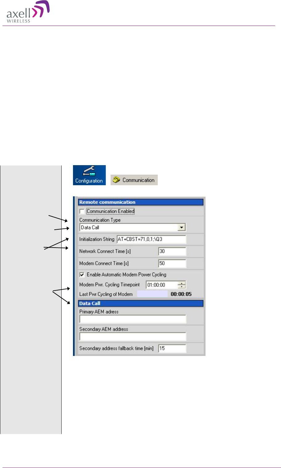
AXELL MBF MULI-BAND FIBRE REPEATER
PRODUCT DESCRIPTION AND USER’S MANUAL
38 © Axell Wireless Ltd
7
7.
.4
4
C
Co
om
mm
mu
un
ni
ic
ca
at
ti
io
on
n
v
vi
ia
a
W
Wi
ir
re
el
le
es
ss
s
M
Mo
od
de
em
m
There are two different ways of communication for a wireless (GSM) modem:
Using data call / modem connection.
Note! This requires the SIM-card in the modem to be configured with data service.
Using SMS to configure the repeater with simple text messages
Note! SMS functionality is not implemented in this SW release.
The Axell Element Manager always uses data call communication with the repeater, why all repeaters
being controlled by the AEM must have data service enabled on the SIM card.
Configuring the repeater to send alarms and reports via SMS it is still possible to establish data calls
to the repeater, as long as the SIM card is data service enabled.
7.4.1 Modem Configuration, not using GPRS
Select
“Configuration”
and
“Communication”
Select Data Call
Initialization string
Connect times
AEM addressed are
set via the AEM
Select Data Call
Set the modem initialization string. This string differs between networks.
Primary recommendation is AT+CBST=71,0,1;\Q3. If remote
communication cannot be established try 7,0,1 or 0,0,1 or 7,0,3. For more
information please refer to the section on Troubleshooting Remote
Communication.
Tick “Enable Automatic Modem Power Cycling” for the modem to be
power cycled once every 24 hours. Set the time at which the modem should
be tested. This function ensures that the repeater always is logged in to the
network.
2004-01-01
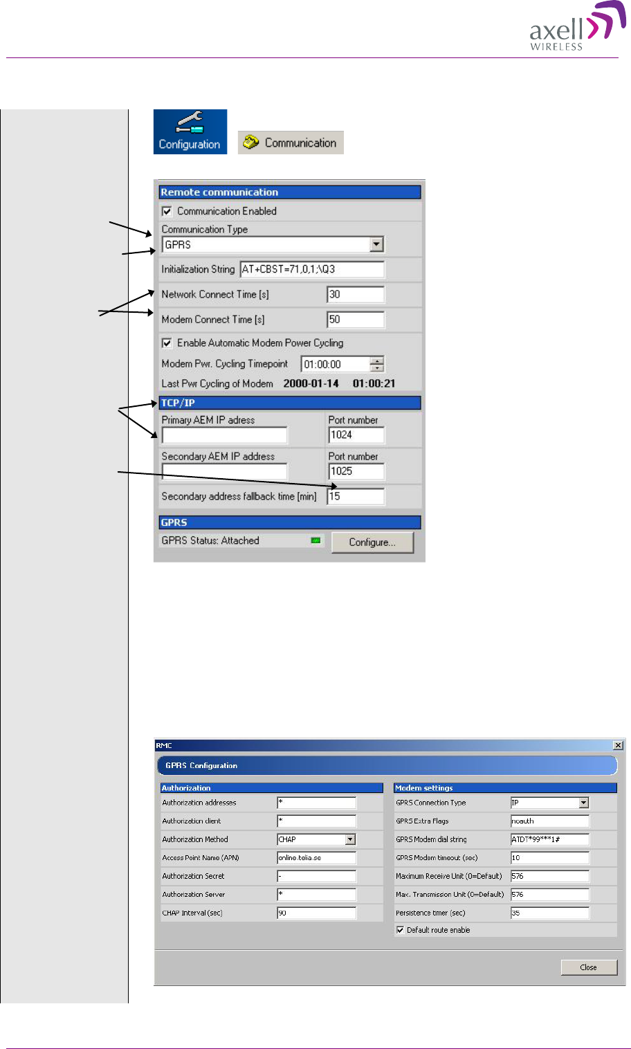
AXELL MBF MULI-BAND FIBER REPEATER
PRODUCT DESCRIPTION AND USER’S MANUAL
© Axell Wireless Ltd 39
7.4.2 Modem Configuration, using GPRS
Select
“Configuration”
and
“Communication”
Select GPRS
Initialization
string
Connect times
AEM addressed
are set via the
AEM
Configure GPRS
Select GPRS
Set the modem initialization string. This string differs between networks.
Primary recommendation is AT+CBST=71,0,1;\Q3
Tick “Enable Automatic Modem Power Cycling” for the modem to be power
cycled once every 24 hours. Set the time at which the modem should be
tested. This function ensures that the repeater always is logged in to the
network.
Click on Configure…
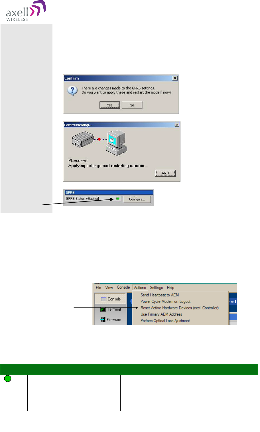
AXELL MBF MULI-BAND FIBRE REPEATER
PRODUCT DESCRIPTION AND USER’S MANUAL
40 © Axell Wireless Ltd
Each parameter is described in Common Commands and Attributes, section
14 GPRS Configurations.
Set the Access Point Name. It needs to be defined by the telecom operator
Set Maximum Receive Unit and maximum Transmission Unit. These differ
depending on access type: 576 for GSM, 1476 for EDGE and 1500 for
WCDMA.
Click on Close, and then on “Yes”.
Wait for the modem to restart. This can take a few minutes.
When the modem settings are ready the LED turn green.
7.4.2.1 Modem Verification
When the remote configuration has been set up the communication can be verified using the modem
feature of the RMC and dialling the data number. The remote communication is verified as soon as a
successful remote login to the repeater has been performed.
However, as a first step, it is recommended to verify that the modem is initialized correctly. After
configuring the modem using the RMC, make sure to initiate a power cycling of the modem. This is
done from the RMC menu.
Click on the drop-down menu
Actions, choose Power Cycle
Modem on Logout
An immediate power cycling is initiated after which the modem is initialized and registered onto the
network. The modem is now ready for remote access.
Ensure a successful configuration by observing the modem LED as described below.
Note! This LED behaviour is valid only for GSM modems. Other modem types will be added in later
editions.
Green LED – Modem Status
On
Depending on type of call:
Voice call: Connected to remote party
Data call: Connected to remote party or exchange
of parameters while setting up or disconnecting a
call
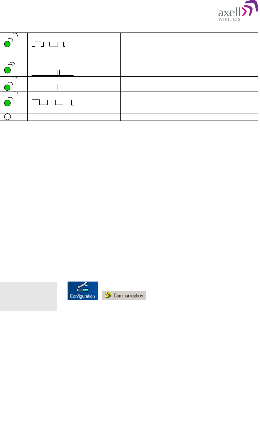
AXELL MBF MULI-BAND FIBER REPEATER
PRODUCT DESCRIPTION AND USER’S MANUAL
© Axell Wireless Ltd 41
Flashing
(irregular)
Indicates GPSR data transfer. When a GPRS
transfer is in progress the LED goes on within 1
second after data packets were exchanged. Flash
duration in approximately 0.5s.
75ms on/75ms off/75ms on/3s off
One or more GPRS contexts activated
75ms on/3s off
Logged to network (monitoring control channels
and user interactions). No call in progress
600ms on/600ms off
No SIM card inserted, or no PIN entered, or
network search in progress, or ongoing user
authentications, or network login in progress
Off
Modem is off
Verify the remote communication either by having someone attempting to integrate the repeater from
the Axell Element Manager, or by dialling the repeater using the Repeater Maintenance Console.
Note! It is very important to dial the data number of the SIM. In case the voice number is dialled, the
call is answered, but almost immediately the call will be hung up.
7.4.2.2 SIM-card Using Single Numbering Scheme
If the network is configured using Single Numbering Scheme (SNS), some special considerations
apply.
The repeaters are by default configured so that networks using SNS always will have calls routed to
the data service in the modem. When dialling from within the network to a repeater having an SNS-
configured SIM will operate normally, since the call originator informs the system that the bearer is
of type DATA. However, when dialling from outside the network trying to connect to the repeater
can be difficult. Depending on the interface to the roaming network or to the PSTN network if an
analogue modem is used, the bearer type can default to voice. If the bearer is set to voice, the data
service cannot be converted to DATA, and a call setup cannot be completed.
Note! This is not a repeater related problem; the solution is to verify how the external network
interfaces handles the VOICE vs. DATA bearer type.
7.4.3 Configuration via PSTN (Fixed) Modem
Also for PSTN modems data call shall be used.
Select
“Configuration”
and
“Communication”
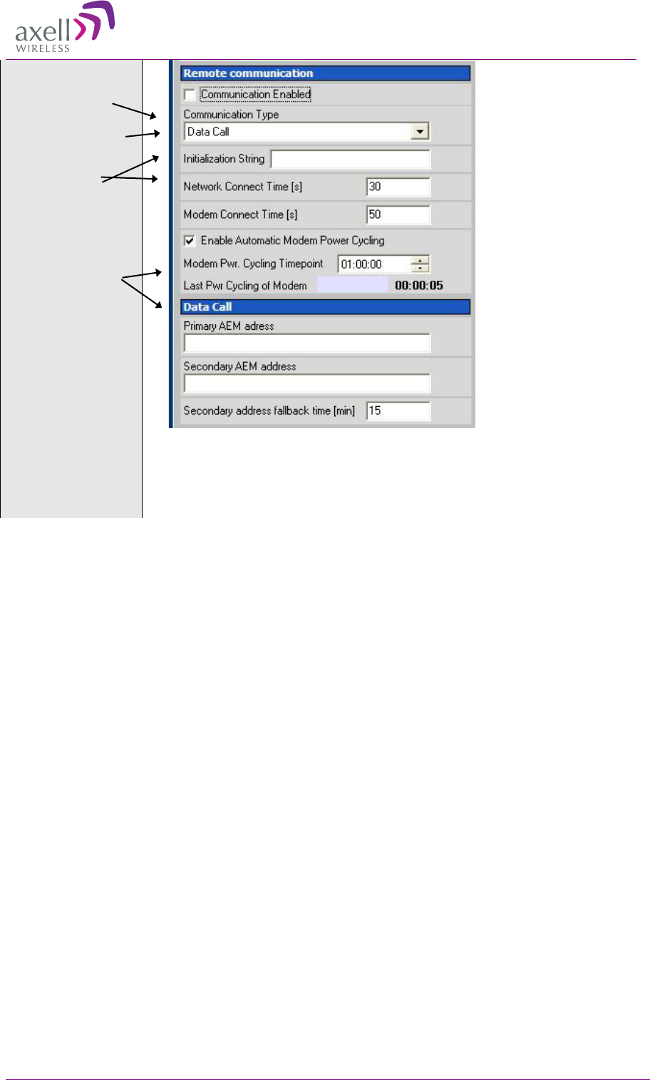
AXELL MBF MULI-BAND FIBRE REPEATER
PRODUCT DESCRIPTION AND USER’S MANUAL
42 © Axell Wireless Ltd
Select Data Call
Initialization string
Connect times
AEM addressed are
set via the AEM
Tick “Enable Automatic Modem Power Cycling” for the modem to be
power cycled once every 24 hours. Set the time at which the modem should
be tested. This function ensures that the repeater always is logged in to the
network.
7
7.
.5
5
T
Tr
ro
ou
ub
bl
le
es
sh
ho
oo
ot
ti
in
ng
g
R
Re
em
mo
ot
te
e
C
Co
om
mm
mu
un
ni
ic
ca
at
ti
io
on
n
Please also refer to the document Common Command and Attributes for guidance.
Since many networks have their own “personality”, performing first time configuration of the remote
communication sometimes requires tweaking of the modem parameters.
This section describes some trouble shooting techniques if configuring the repeater for remote access
fails.
The illustration below is a simplified schematic of the remote communication between a GSM
modem in a repeater and an analogue modem. The analogue modem in the computer communicates
with the Interworking Function Unit (IFU), which is the GSM network analogue network interface.
The call is routed via the switch centre over the air interface to the data call number in the SIM-card
of the GSM module.
The Control Module is responsible for establishing connections with the Axell Element Manager, and
to answer incoming calls to the repeater.
As described in previous sections, the Control Module only accepts one login at a time, either via
Local Maintenance port (LMT) or modem connection. Hence, when verifying the remote access of
the repeater, it is important to log out from the repeater locally before trying to access the repeater
remotely.
2004-01-01
ATE0S0=0
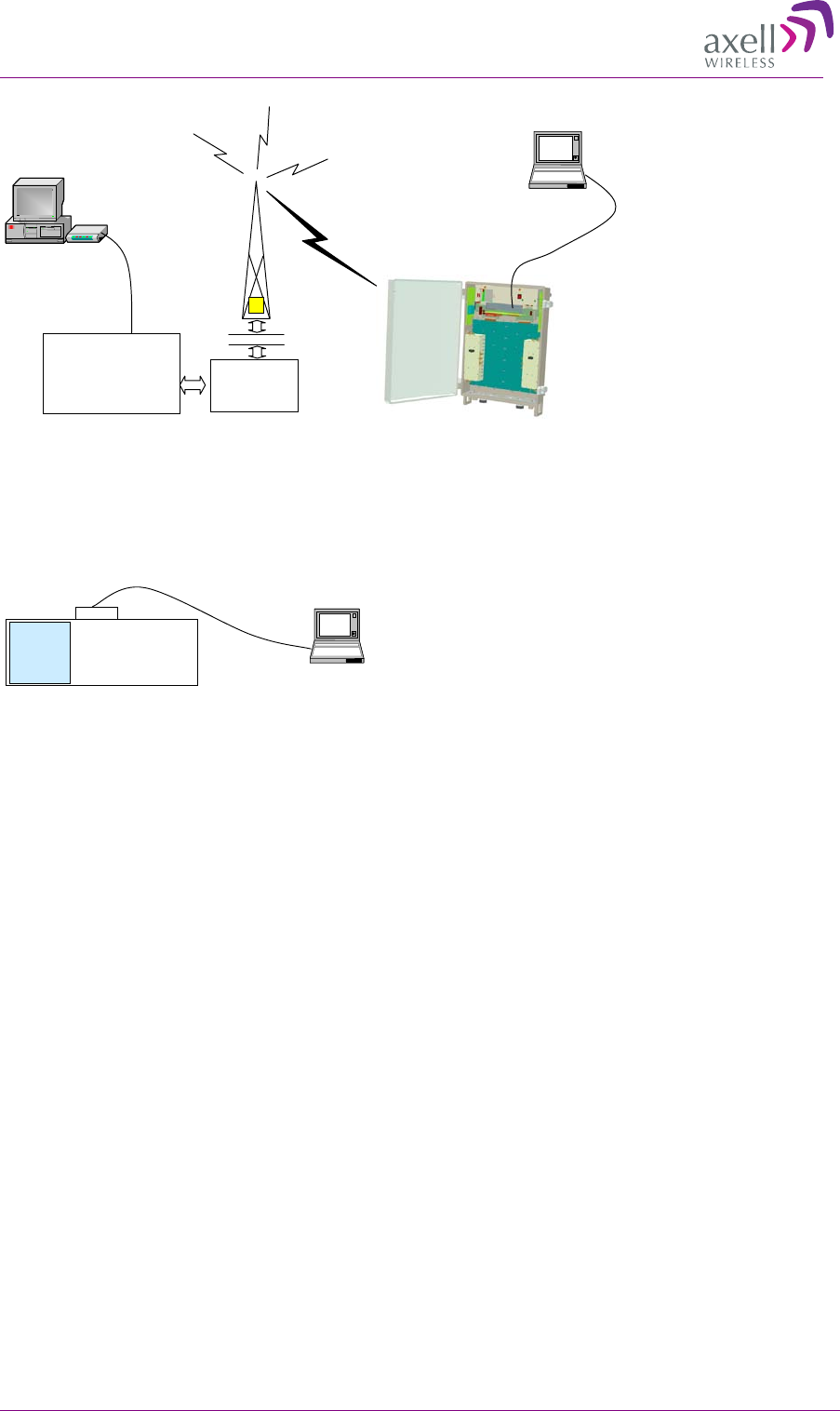
AXELL MBF MULI-BAND FIBER REPEATER
PRODUCT DESCRIPTION AND USER’S MANUAL
© Axell Wireless Ltd 43
7.5.1 Direct Modem Access
To allow for advanced trouble shooting of the communications, it is possible to access the modem
directly via the Control Module from a laptop computer.
Log in to the repeater, either with RMC, or with a terminal emulation program, such as
HyperTerminal™. When the login is completed, select Terminal Mode, this will give access to the
repeater command prompt in the same way as with HyperTerminal.
When the repeater prompt is accessible, type in the command
ACCESS MODEM <Enter>.
When typing ACCESS MODEM, the controller will send all the characters that are typed directly out
to the modem port. All characters replied back from the modem will go directly to the LMT port and
back to the computer.
To abort an ACCESS MODEM session, press three ‘-‘ in a row (all three within one second) to come
back to the repeater command prompt.
Note! When accessing the modem port the modem might be configured with “echo off”, meaning
that the characters entered will not be echoed back to the screen. In order to enable “echo”, press
Enter.
Type
ATE1 <enter>
(invisible)
The modem replies with
OK
indicating that the echo is enabled. All characters entered will now be echoed back to the terminal
program.
7.5.2 Trace Modem
For troubleshooting purposes it is possible to trace the actual progress of initializing the modem. This
trace is useful when having problems with the modem initialization.
Go to Terminal Mode and type
TRACE MODEM
Radio
LinkProtocol
(RLP)
Base Station
LaptopLaptop
Control module in
Axell Wireless
Repeater
Switch
Centre
ModemModem RS232
Interworking
Function Unit
(IFU)
LaptopLaptop
RS232 cable
Control Module
GSM
Module
LMT Port

AXELL MBF MULI-BAND FIBRE REPEATER
PRODUCT DESCRIPTION AND USER’S MANUAL
44 © Axell Wireless Ltd
To end session type CTRL-Z
7.5.3 Manually Answering Incoming Calls
It is possible to manually answer incoming calls without involving the repeater software at all, to
verify that the remote access and the network itself works as intended. In order to verify the remote
communication, make sure to have someone stand by to dial up the repeater with a terminal
emulation program, for example HyperTerminal™.
Go in to Direct Modem Access as described earlier. When in direct access mode, ask the person
standing by to dial up the repeater.
As soon as a call is received, the text
RING
will repeatedly be displayed on the screen.
Type
ATA <enter>
This will inform the modem to answer (ATtention Answer).
When the connection is established, a connect message will be displayed including the connection
speed. Sometimes the information comes together with some miscellaneous information, such as
error correction protocols etc.
Note! Make sure the remote peer dials the Data Call number
If the voice number is dialled instead of the data number, or if the modem contains an illegal modem
initialization string, the message
OK
or
NO CARRIER
will be displayed almost immediately.
Try to change the modem initialization string. The modem initialization string mainly used to
configure the remote communication is AT+CBST.
Successful modem initialization strings used by Axell Wireless includes (most common first):
AT+CBST=71,0,1;\Q3
AT+CBST=7,0,1;\Q3
AT+CBST=0,0,1;\Q3
AT+CBST=0,0,1;\Q3
AT+CBST=7,0,3;\Q3
Once the modem initialization string is entered, try again to dial up the repeater. For details on the
different modem initialization strings, please refer to the modem’s user guide.
If the setup is successful, the connect message will be brought up;
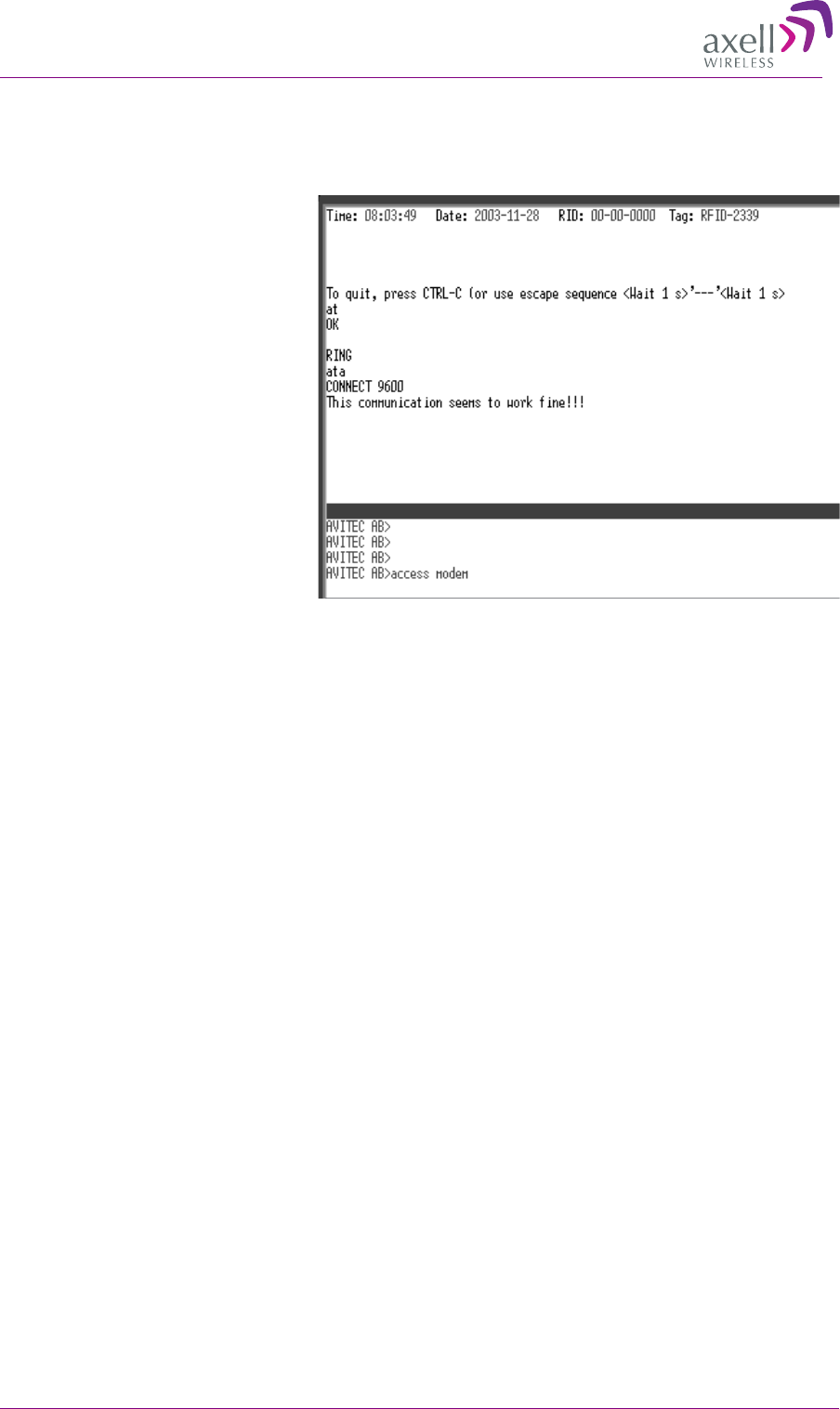
AXELL MBF MULI-BAND FIBER REPEATER
PRODUCT DESCRIPTION AND USER’S MANUAL
© Axell Wireless Ltd 45
CONNECT 9600
This means that an online connection is established to the remote peer. From now on, all characters
typed on the keyboard will end up on the remote peer’s screen. Similarly, all characters typed by the
remote peer will be displayed on the screen.
In the example, the incoming call
was successfully answered, and the
remote user entered the text
message.
In order to come back to modem command mode, press +++ (three pluses) rapidly (within one
second).
Receiving
OK
means that the modem is back in command mode.
Type
ATH <enter>
This terminates the connection to the remote peer. The message
NO CARRIER
will be displayed.
7.5.4 Common Problems
7.5.4.1 Problem 1
When enabling the remote access for the repeater, the modem fails to log in to the network.
7.5.4.2 Solution
Signal strength from the donor site is too low. The signal strength can be read directly from the
modem. Go in to Direct Modem Access as described earlier. Use the command AT+CSQ
(documented below) to read out the signal strength.
In order to have good signal quality, Axell Wireless recommends that the signal strength should be
better than -95 dBm. If signal strength is lower, try to adjust the antennas to get a better signal
strength from the donor.
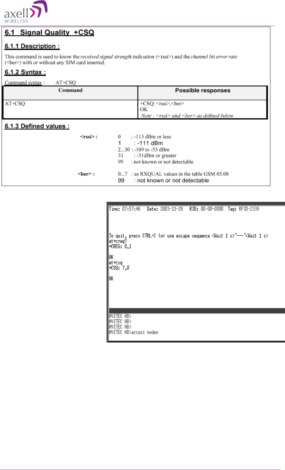
AXELL MBF MULI-BAND FIBRE REPEATER
PRODUCT DESCRIPTION AND USER’S MANUAL
46 © Axell Wireless Ltd
Documentation of +CSQ command from a modem’s manual.
In the example the reply to
AT+CSQ is 0,7 meaning 7*2 dB
above -113 dBm; the modem
detects a signal level of -99 dBm.
7.5.4.3 Problem 2a
Repeater is configured properly, and answers the incoming call, but when trying to dial the repeater
using an analogue mode, no modem handshaking is heard from the dialling modem.
7.5.4.4 Problem 2b
When dialling the repeater, the repeater answers the incoming call, but no connection is established,
and after a while the repeater disconnects the call.
7.5.4.5 Solution
The most common cause is that the number called is the voice number of the SIM, not the data
number. Therefore, make sure to dial the data number.
If data call is used, the problem probably is an illegal modem initialization string.
In order to change the modem string, go to the repeater command prompt. Try changing the modem
initialization string and log out to let the controller reinitialize the modem.

AXELL MBF MULI-BAND FIBER REPEATER
PRODUCT DESCRIPTION AND USER’S MANUAL
© Axell Wireless Ltd 47
If problem remains, try a few different modem initialization strings. Axell Wireless has been
successful with the following modem initialization strings:
AT+CBST=71,0,1;\Q3
AT+CBST=7,0,1;\Q3
AT+CBST=0,0,1;\Q3
AT+CBST=0,0,1;\Q3
AT+CBST=7,0,3;\Q3
Please refer to the modem manual for detailed description of the modem initialization strings.
7.5.4.6 Problem 3
It is possible to call the repeater from another GSM mobile, but not from an analogue modem.
7.5.4.7 Solution
This problem is most likely related to the modem configuration and/or the configuration of the IFU
unit. Try to decrease the communications speed and make sure that the modem error correction is
supported by the IFU. Verify the IFU configuration to see if there are any known problems with the
modem connections.
7.5.4.8 Problem 4
When dialling the repeater, or when the repeater is dialling the Element Manager, the connection is
terminated before the handshaking is completed.
7.5.4.9 Solution
When a repeater is answering an incoming modem call, or calling up the OMC to deliver an alarm or
a report, the repeater will wait a configurable number of seconds for the call to be established. If no
communication is established within this time, the call will be hung up. If this interval is set too low,
the handshaking is terminated too fast. In the RMC, verify the Modem Connect Time to see that it is
set to at least 30 seconds.

AXELL MBF MULI-BAND FIBRE REPEATER
PRODUCT DESCRIPTION AND USER’S MANUAL
48 © Axell Wireless Ltd
8
8
S
Sp
pe
ec
ci
if
fi
ic
ca
at
ti
io
on
ns
s
Note! All data is subject to change without prior notice.
8
8.
.1
1
S
Si
in
ng
gl
le
e
B
Ba
an
nd
d
R
Re
ep
pe
ea
at
te
er
r
M
MB
BF
F-
-S
S-
-7
7/
/8
8/
/9
9/
/1
17
7/
/1
18
8/
/1
19
9/
/2
22
2
Electrical Specifications
LTE 700 GSM/WCDMA
850 E-
GSM GSM1800 GSM/WCDMA
1900 AWS WCDMA2100
UL 698-716MHz
and
777-787MHz
824 – 849 MHz 880 –
915
MHz
1710 -
1785 MHz 1850 - 1910
MHz 1710-1755
MHz 1920 - 1980 MHz
DL 728-756MHz 869 – 894 MHz 925 –
960
MHz
1805 -
1880 MHz 1930 - 1990
MHz 2110-2155
MHz 2110 - 2170 MHz
Operational
bandwidth 28MHz/18MHz/
10MHz 25MHz 35
MHz 75MHz 60 MHz 45MHz 60 MHz
Composite
Output Power
DL
+37dBm +37 dBm +37
dBm +37 dBm +37 dBm -39 dBm
(for PAR of
8.5 dB)
+39 dBm (for
PAR of 8.5 dB)
Ripple in pass band (all bands) < 2 dB
Noise figure UL (all bands) 3 dB typical (maximum gain)
Propagation delay (all bands) < 2 µs
Modulation Accuracy at nominal output power
LTE <3%EVM RMS
GSM / GMSK < 2.5 ° RMS and < 10 ° peak
EDGE / 8-PSK < 3 % EVM RMS
WCDMA/EVM < 12.5% RMS (composite according to ETSI TS 25.106
with TM 1/64 DPCH)
WCDMA/PkDCE < -33 dB (according to ETSI TS 25.106 with TM 1/64
DPCH and spreading factor 256)
Gain UL/DL (all bands) Adjustable in 1 dB steps
System Impedance 50 ohm
Return Loss at Antenna Connection > 14 dB
Antenna connectors DIN 7/16
Electrical ratings 230 VAC, 50 Hz or -48 VDC
Power Consumption 140 W

AXELL MBF MULI-BAND FIBER REPEATER
PRODUCT DESCRIPTION AND USER’S MANUAL
© Axell Wireless Ltd 49
Optical Module Electrical Specification
Laser class Class 3B
Optical power level +3dBm ±2dBm
Optical Wavelength
Two colour system Three colour system Four colour system
Master 1310 ± 10 nm 1310 ± 10 nm 1310 ± 10 nm
Slave 1 1550 ± 3 nm 1550 ± 3 nm 1530 ± 3 nm
Slave 2 NA 1510 ± 3 nm 1510 ± 3 nm
Slave 3 NA NA 1550 ± 3 nm
Mechanical Specifications
Dimensions 540 x 350 x 150 mm
Enclosure Aluminium (IP 65)
Weight 20 kg
Environmental Specifications
Cooling Convection*
EMC See compliance below
Operating Temperature - 25 to + 55 ° C
Storage - 30 to + 70 ° C
Humidity ETSI EN 300 019-2-4 (see compliance below)
MTBF > 100 000 hrs
Complies in applicable parts, relevant on different markets, to:
R&TTE Directive including
ETS EN 301 502 (ETS EN 300 609-4/GSM 11.26)
ETSI TS 25.106, ETSI 25.143
ETSI EN 301 908-11
ETS EN 301 498-8
EN 60 950
EN 50 385
* The MBF repeaters are designed primarily for multi carrier purposes. If the repeaters are run at full
output power over a longer period the convection cooling might not be enough. The repeaters have a
power management function implemented that will step down the power and if needed fully shut
down the amplifier chains until temperature has reached normal values. In situations where a repeater
will be run in such a manner extra cooling can be provided for instance by putting the repeater in a
temperature controlled environment or via external fans.

AXELL MBF MULI-BAND FIBRE REPEATER
PRODUCT DESCRIPTION AND USER’S MANUAL
50 © Axell Wireless Ltd
8
8.
.2
2
D
Du
ua
al
l
B
Ba
an
nd
d
R
Re
ep
pe
ea
at
te
er
r
M
MB
BF
F-
-D
D-
-9
9-
-2
22
2/
/8
8-
-1
19
9/
/7
7-
-1
17
7
Electrical Specifications
LTE 700 GSM/WCDMA
850 E-GSM GSM/WCDMA
1900 AWS WCDMA2100
UL 698-716MHz
and
777-787MHz
824 – 849 MHz 880 –
915 MHz 1850 - 1910 MHz 1710-1755 MHz 1920 - 1980 MHz
DL 728-756MHz 869 – 894 MHz 925 –
960 MHz 1930 - 1990 MHz 2110-2155 MHz 2110 - 2170 MHz
Operational
bandwidth 28MHz/18MHz/
10MHz 25MHz 35 MHz 60 MHz 45MHz 60 MHz
Composite Output
Power DL +37dBm +37 dBm +37 dBm +37 dBm -39 dBm (for
PAR of 8.5 dB) +39 dBm (for PAR
of 8.5 dB)
Ripple in pass band (all bands) < 2 dB
Noise figure UL (all bands) 3 dB typical (maximum gain)
Propagation delay (all bands) < 2 µs
Modulation Accuracy at nominal output power
LTE 700 <3% EVM RMS
GSM / GMSK < 2.5 ° RMS and < 10 ° peak
EDGE / 8-PSK < 3 % EVM RMS
WCDMA/EVM < 12.5% RMS (composite according to ETSI TS 25.106
with TM 1/64 DPCH)
WCDMA/PkDCE < -33 dB (according to ETSI TS 25.106 with TM 1/64
DPCH and spreading factor 256)
Gain UL/DL (all bands) Adjustable in 1 dB steps
System Impedance (all bands) 50 ohm
Return Loss at Antenna Connection > 14 dB
Antenna connectors DIN 7/16
Electrical ratings 230 VAC, 50 Hz or -48 VDC
Power Consumption 220 W

AXELL MBF MULI-BAND FIBER REPEATER
PRODUCT DESCRIPTION AND USER’S MANUAL
© Axell Wireless Ltd 51
Optical Module Electrical Specification
Laser class Class 3B
Optical power level +3dBm ±2dBm
Optical Wavelength
Two colour system Three colour system Four colour system
Master 1310 ± 10 nm 1310 ± 10 nm 1310 ± 10 nm
Slave 1 1550 ± 3 nm 1550 ± 3 nm 1530 ± 3 nm
Slave 2 NA 1510 ± 3 nm 1510 ± 3 nm
Slave 3 NA NA 1550 ± 3 nm
Mechanical Specifications
Dimensions 540 x 350 x 150 mm
Enclosure Aluminium (IP 65)
Weight 22 kg
Environmental Specifications
Cooling Convection*
EMC See compliance below
Operating Temperature - 25 to + 55 ° C
Storage - 30 to + 70 ° C
Humidity ETSI EN 300 019-2-4 (see compliance below)
MTBF > 100 000 hrs
Complies in applicable parts, relevant on different markets, to:
R&TTE Directive including
ETS EN 301 502 (ETS EN 300 609-4/GSM 11.26)
ETSI TS 25.106, ETSI 25.143
ETSI EN 301 908-11
ETS EN 301 498-8
EN 60 950
EN 50 385
* The MBF repeaters are designed primarily for multi carrier purposes. If the repeaters are run at full
output power over a longer period the convection cooling might not be enough. The repeaters have a
power management function implemented that will step down the power and if needed fully shut
down the amplifier chains until temperature has reached normal values. In situations where a repeater
will be run in such a manner extra cooling can be provided for instance by putting the repeater in a
temperature controlled environment or via external fans.

AXELL MBF MULI-BAND FIBRE REPEATER
PRODUCT DESCRIPTION AND USER’S MANUAL
52 © Axell Wireless Ltd
8
8.
.3
3
T
Tr
ri
i
B
Ba
an
nd
d
R
Re
ep
pe
ea
at
te
er
r
M
MB
BF
F-
-T
T-
-9
9-
-1
18
8-
-2
22
2/
/8
8-
-1
17
7-
-1
19
9
Electrical Specifications
LTE 700 GSM/WCDMA
850 E-GSM GSM1800 GSM/WCDMA
1900 WCDMA
2100 AWS
UL 698-716MHz
and
777-787MHz
824 – 849 MHz 880 – 915
MHz 1710 - 1785
MHz 1850 - 1910
MHz 1920 - 1980
MHz 1710-1755
MHz
DL 728-756MHz 869 – 894 MHz 925 – 960
MHz 1805 - 1880
MHz 1930 - 1990
MHz 2110 - 2170
MHz 2110-2155
MHz
Operational
bandwidth 28MHz/18MHz/
10MHz 25MHz 35 MHz 75MHz 60 MHz 60 MHz 45MHz
Composite
Output
Power DL
+37dBm +37 dBm +37 dBm* +37 dBm* +37 dBm +39 dBm
(for PAR of
8.5 dB)
+39 dBm
(for PAR of
8.5 dB)
* In repeaters that share a common downlink fibre for 900MHZ and 1800MHz a minimum of 4
carriers in each band is required for the full composite output power to be attainable maintaining full
ETSI compliance
Ripple in pass band (all bands) < 2 dB
Noise figure UL (all bands) 3 dB typical (maximum gain)
Propagation delay (all bands) < 2 µs
Modulation Accuracy at nominal output power
GSM / GMSK < 2.5 ° RMS and < 10 ° peak
EDGE / 8-PSK < 3 % EVM RMS
WCDMA/EVM < 12.5% RMS (composite according to ETSI TS 25.106
with TM 1/64 DPCH)
WCDMA/PkDCE < -33 dB (according to ETSI TS 25.106 with TM 1/64
DPCH and spreading factor 256)
Gain UL/DL (all bands) Adjustable in 1 dB steps
System Impedance 50 ohm
Return Loss at Antenna Connection > 14 dB
Antenna connectors DIN 7/16
Electrical ratings 230 VAC, 50 Hz or -48 VDC
Power Consumption 350 W

AXELL MBF MULI-BAND FIBER REPEATER
PRODUCT DESCRIPTION AND USER’S MANUAL
© Axell Wireless Ltd 53
Optical Module Electrical Specification
Laser class Class 3B
Optical power level +3dBm ±2dBm
Optical Wavelength
Two colour system Three colour system Four colour system
Master 1310 ± 10 nm 1310 ± 10 nm 1310 ± 10 nm
Slave 1 1550 ± 3 nm 1550 ± 3 nm 1530 ± 3 nm
Slave 2 NA 1510 ± 3 nm 1510 ± 3 nm
Slave 3 NA NA 1550 ± 3 nm
Mechanical Specifications
Dimensions 540 x 350 x 220 mm
Enclosure Aluminium (IP 65)
Weight 33 kg
Environmental Specifications
Cooling Convection*
EMC See compliance below
Operating Temperature - 25 to + 55 ° C
Storage - 30 to + 70 ° C
Humidity ETSI EN 300 019-2-4 (see compliance below)
MTBF > 100 000 hrs
Complies in applicable parts, relevant on different markets, to:
R&TTE Directive including
ETS EN 301 502 (ETS EN 300 609-4/GSM 11.26)
ETSI TS 25.106, ETSI 25.143
ETSI EN 301 908-11
ETS EN 301 498-8
EN 60 950
EN 50 385
* The MBF repeaters are designed primarily for multi carrier purposes. If the repeaters are run at full output
power over a longer period the convection cooling might not be enough. The repeaters have a power
management function implemented that will step down the power and if needed fully shut down the amplifier
chains until temperature has reached normal values. In situations where a repeater will be run in such a
manner extra cooling can be provided for instance by putting the repeater in a temperature controlled
environment or via external fans.