PBE Europe as Axell Wireless A218SERIES Part 90 Class B Industrial Booster User Manual Installation Guide v03
Axell Wireless Part 90 Class B Industrial Booster Installation Guide v03
UserManual.wiki
>
PBE Europe as Axell Wireless
>
A218SERIES User Manual
Installation Guide v03
Navigation menu
Upload a User Manual
Namespaces
Wiki Guide
HTML
PDF
Info
Views
User Manual
Discussion / Help
Navigation
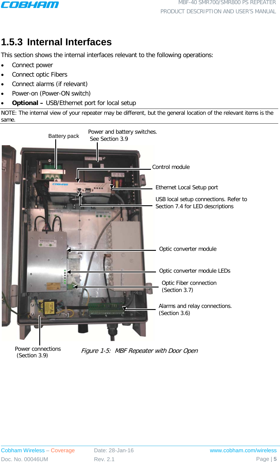
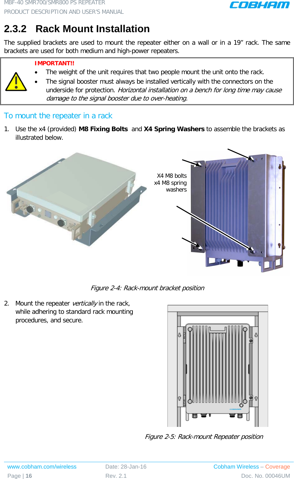
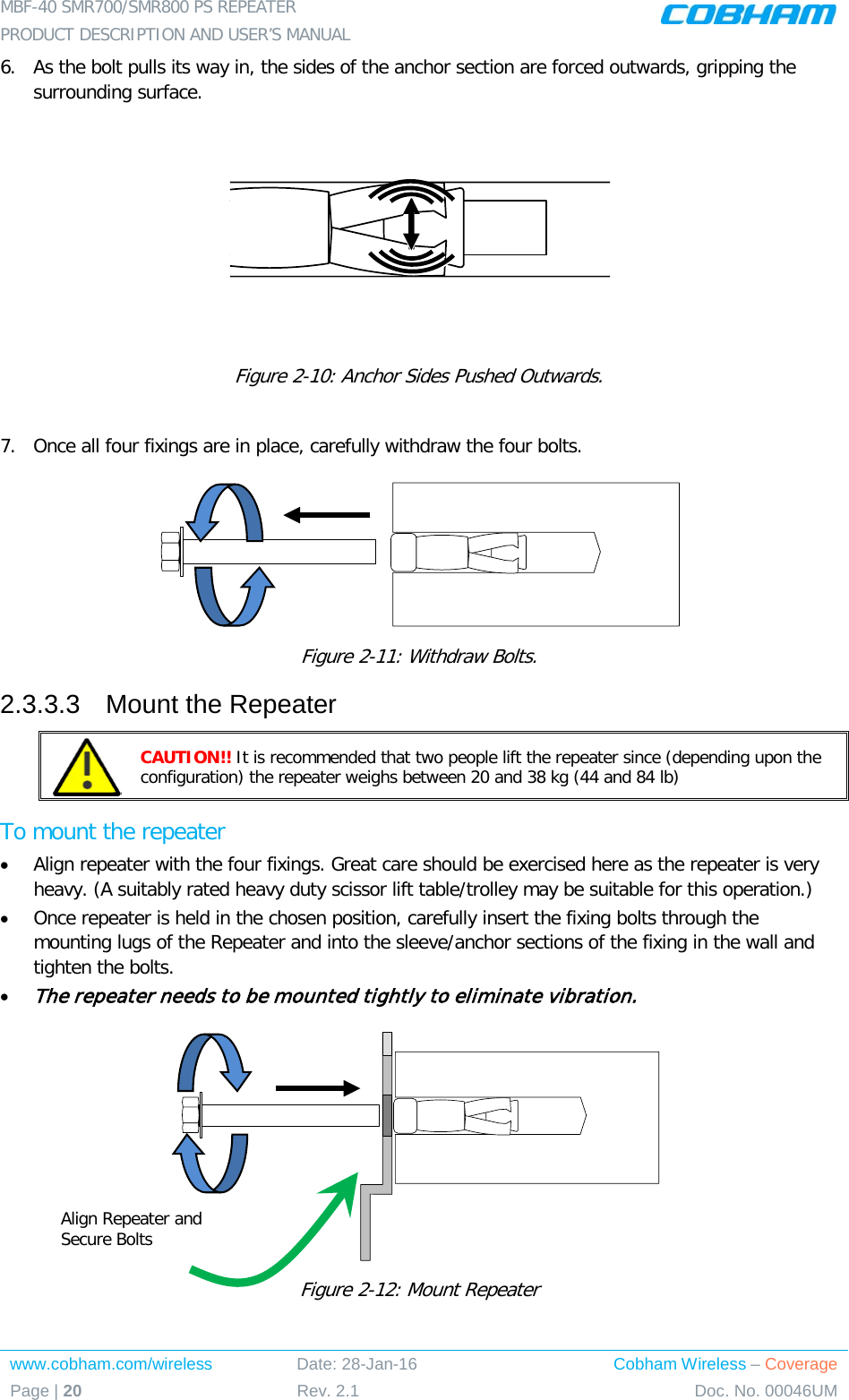
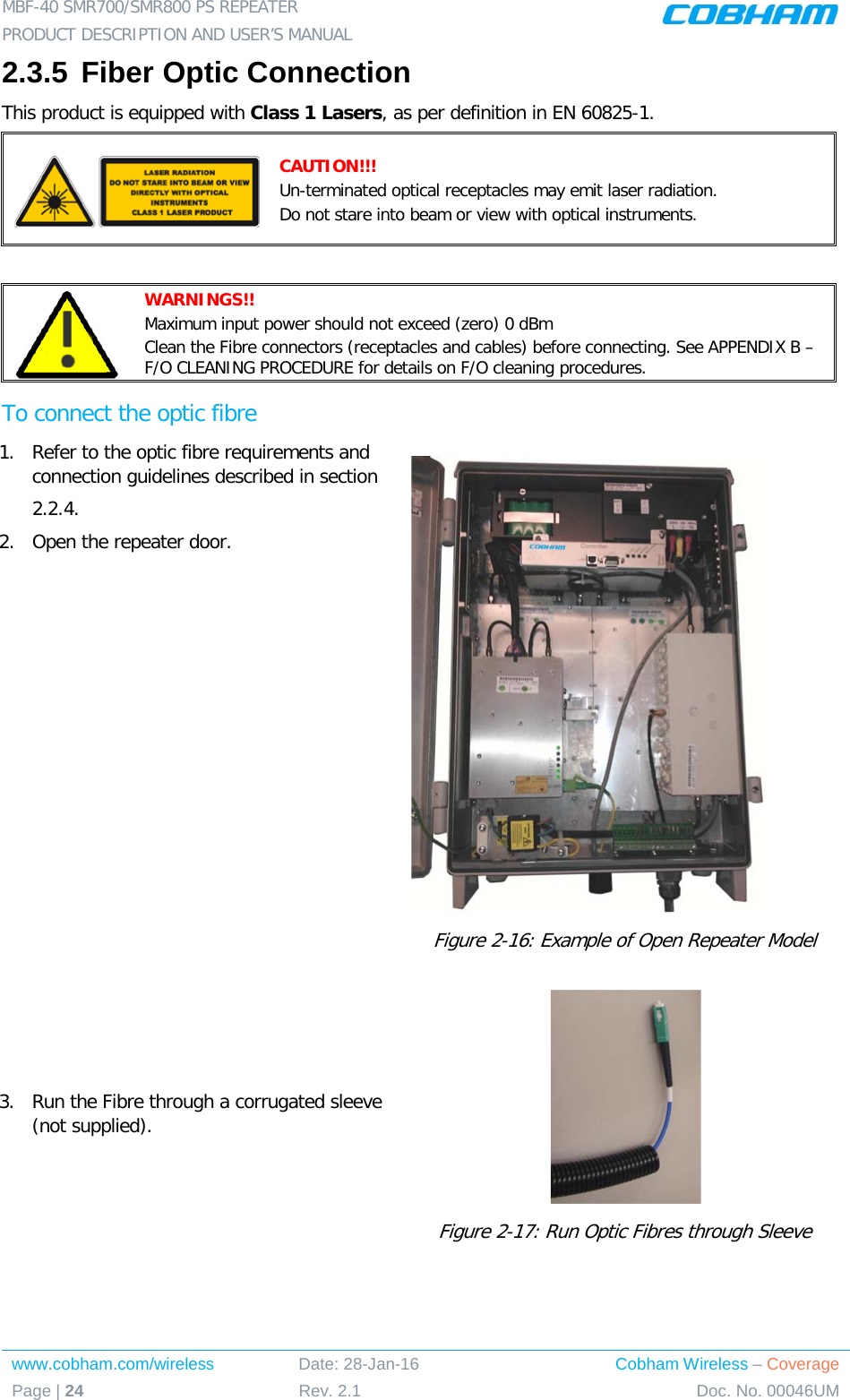
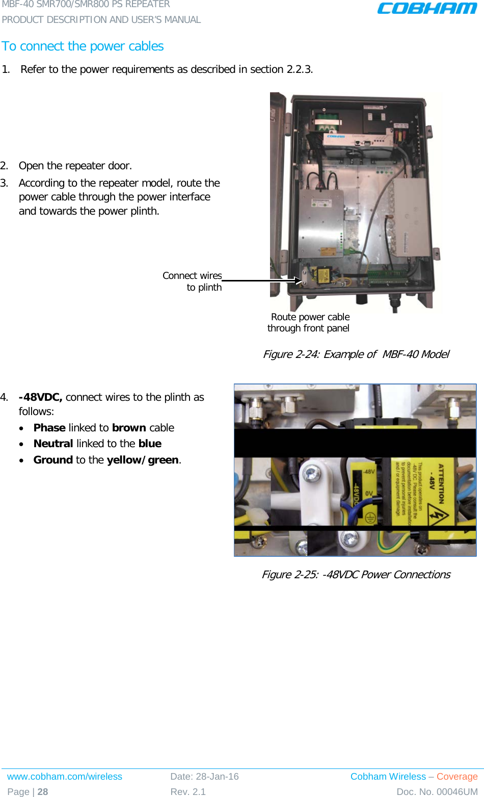
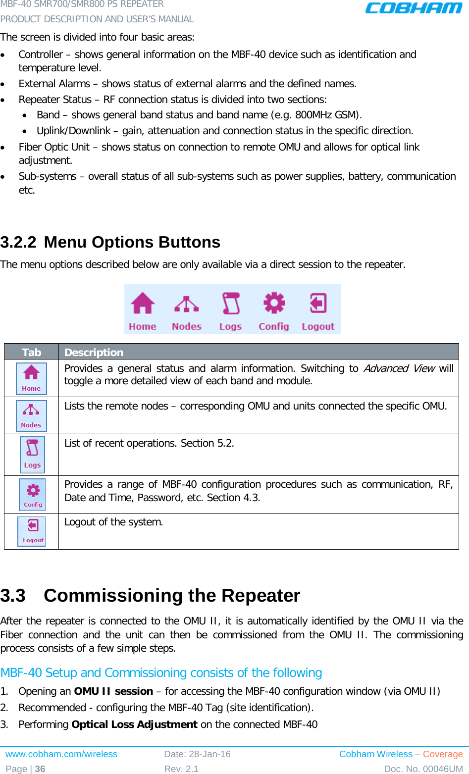
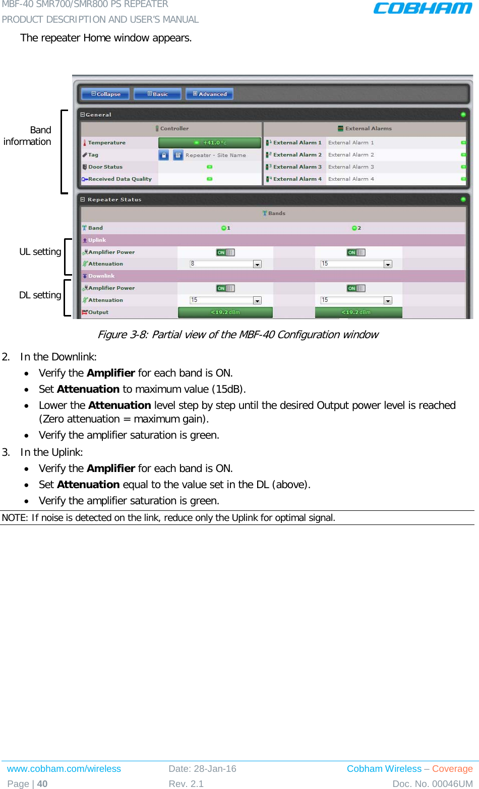
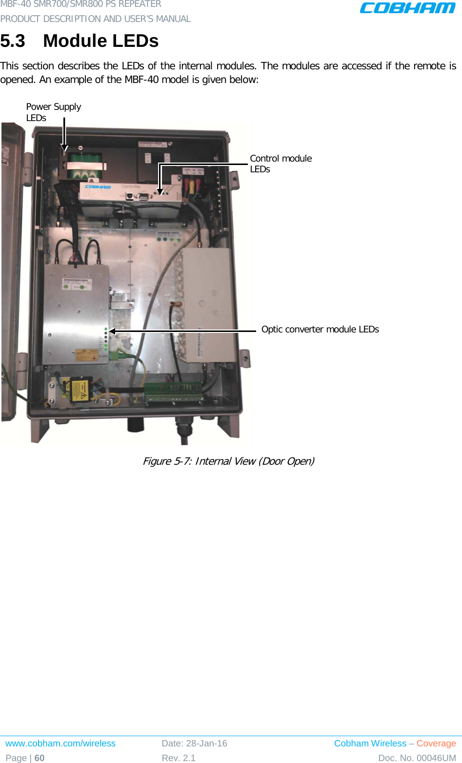
![MBF-40 SMR700/SMR800 PS REPEATER PRODUCT DESCRIPTION AND USER’S MANUAL www.cobham.com/wireless Date: 28-Jan-16 Cobham Wireless – Coverage Page | 6 Rev. 2.1 Doc. No. 00046UM 2 INSTALLATION REQUIREMENTS AND PROCEDURE This chapter provides information on the service antenna requirements, general installation requirements and the installation procedure. 2.1 Service Antenna Requirements This section provides the service antenna requirements in English and in French. 2.1.1 Service Antenna Requirements (English) ATTENTION!! • The installer is held accountable for implementing the rules required for deployment. • Good engineering practice must be used to avoid interference. • Output power should be reduced to solve any IMD interference issues 2.1.1.1 Required Antenna Information NOTE: The Service antenna is installed indoors, where the type of antenna depends on the application. The following antenna requirements, specifications and site considerations should be met: • Type of installation – indoor or outdoor • Service area type and size • Antenna type and characteristics • Height • Length and type of coaxial cable required for connecting the antenna to the Repeater and the attenuation. 2.1.1.2 Indoor Installations FCC & IC Required Compliance Recommended Antennas The following describes the requirements for an omni-directional mobile used for indoor applications. • One or a combination of the following antennas can be used: Ceiling Mount Patch antenna, Wall Mount Patch antenna, Corner Reflector. • Maximum antenna gain for indoor operation 4.14dBi. • Antenna impedance 50 ohms • Cable and jumper loss is at least 2dB. • [Gain Antenna – Cable loss] should not exceed 2.14dB 2.1.1.3 Indoor Installation Antenna Installation Criteria Determine the antenna installation configuration, according to the transmission requirements and the installation site conditions. Installation requirements:](https://usermanual.wiki/PBE-Europe-as-Axell-Wireless/A218SERIES/User-Guide-2951792-Page-18.png)
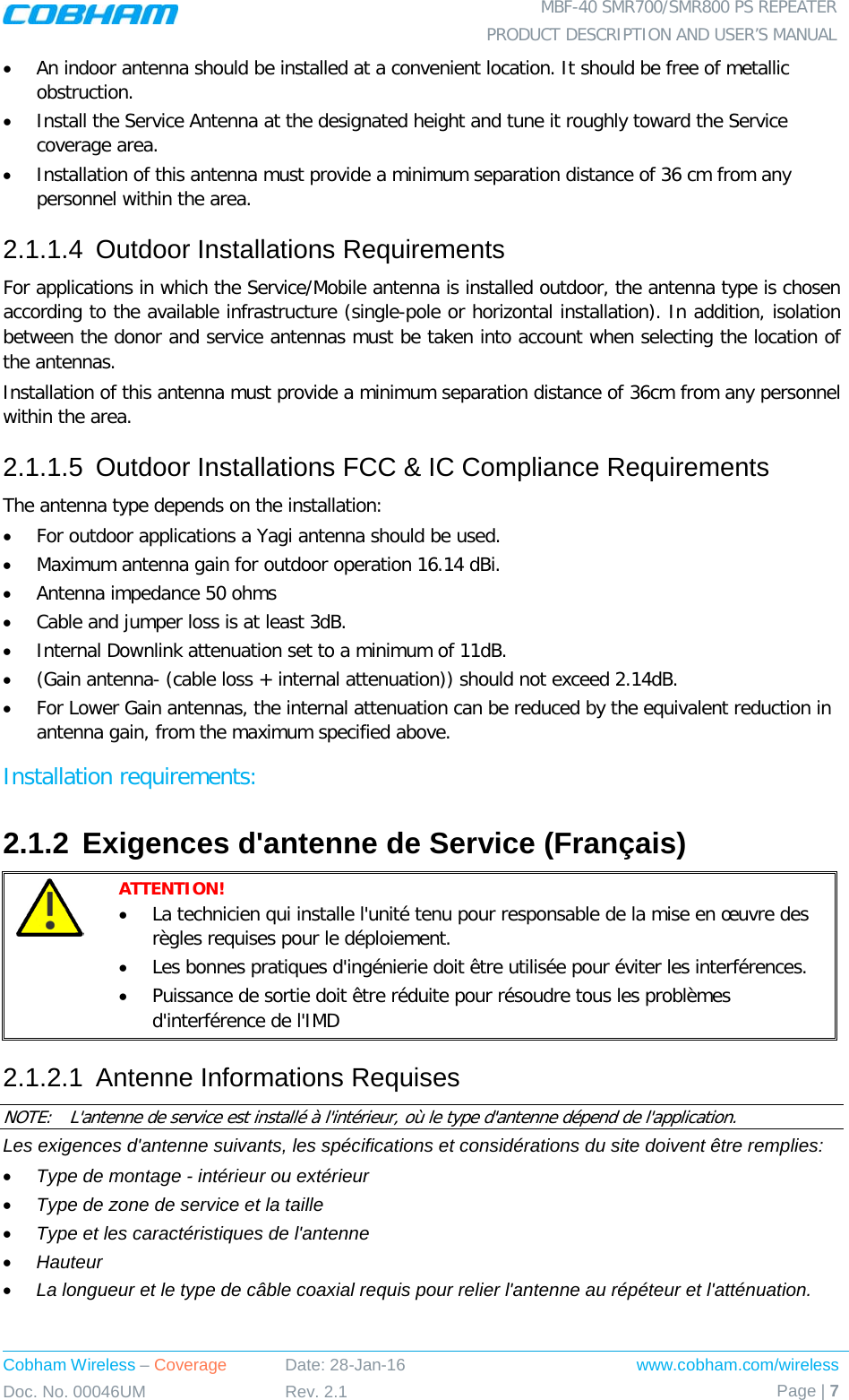
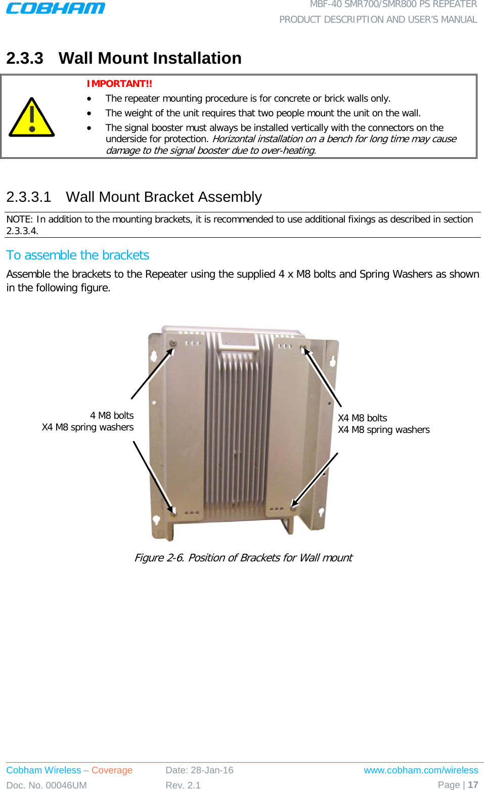
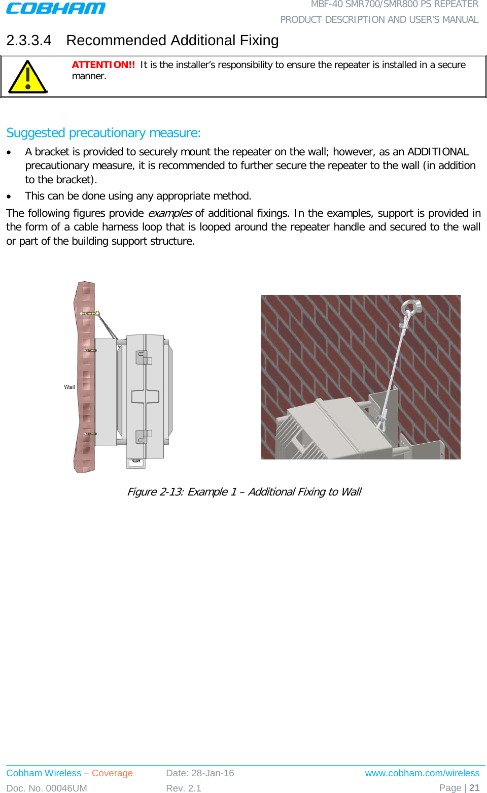
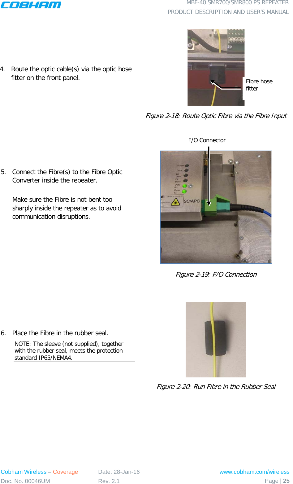
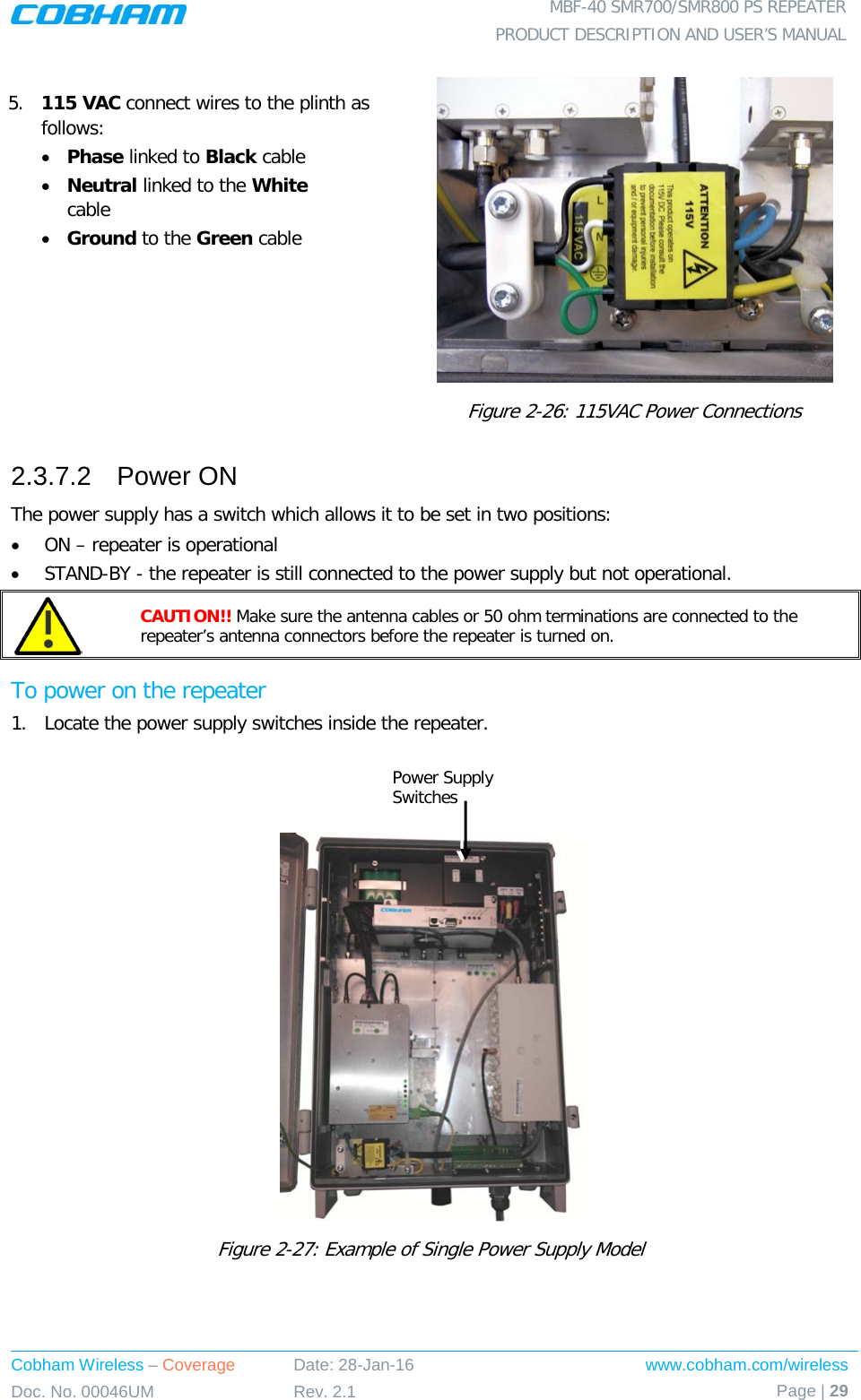
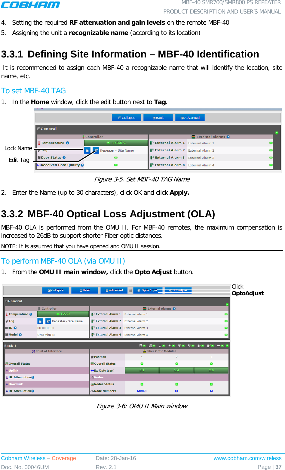
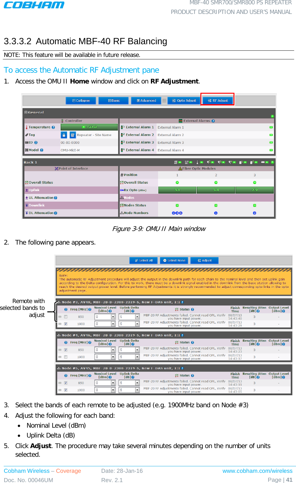
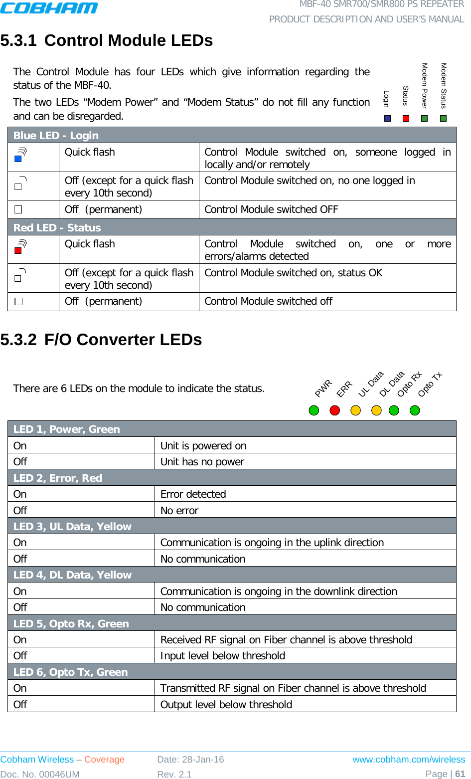
![MBF-40 SMR700/SMR800 PS REPEATER PRODUCT DESCRIPTION AND USER’S MANUAL www.cobham.com/wireless Date: 28-Jan-16 Cobham Wireless – Coverage Page | 8 Rev. 2.1 Doc. No. 00046UM 2.1.2.2 FCC et IC conformité de l'installation intérieure Ci-dessous décrit les exigences pour un portable omnidirectionnel utilisé pour des applications intérieures: • Un ou une combinaison des antennes suivantes peuvent être utilisées: Antenne Patch pour montage au plafond, antenne Patch pour montage mural, Réflecteur en Coin. • gain d'antenne maximal pour une utilisation en intérieur 4.14dBi • Impédance d'antenne: 50 ohms • Câble et la perte de cavalier est d'au moins 2dB. • [Gain Antenna - la perte de câble] ne doit pas dépasser 2.14dB 2.1.2.3 Critères d'installation de l'antenne d'installation d'intérieur Déterminer la configuration de l'installation de l'antenne, selon les exigences de transmission et les conditions du site d'installation. Exigences d'installation: • Une antenne intérieure doit être installée à un endroit pratique. Il doit être libre de tout obstacle métallique. • Installez l'antenne de service à la hauteur désignée et l'accorder à peu près vers la zone de couverture du service. • L'installation de cette antenne doit fournir une distance minimale de séparation de 36 cm de tout le personnel dans la région 2.1.2.4 Installations Extérieures Pour les applications dans lesquelles le antenne du service / mobile est installé extérieure, du type d'antenne est choisi en fonction de l'infrastructure existante (unipolaire ou installation horizontale). En outre, l'isolement entre le donneur et les antennes de service doit être pris en compte lors du choix de l'emplacement des antennes. L'installation de cette antenne doit fournir une distance minimale de séparation de 36cm de tout le personnel dans la région. 2.1.2.5 FCC et IC conformité pour Installation à l'extérieur Le type d'antenne dépend de l'installation • Pour les applications extérieures une antenne Yagi doit être utilisé. • Gain d'antenne maximal pour l'utilisation en extérieur 16.14dBi. • Impédance d'antenne: 50 ohms • La perte de câble et la perte de cavalier est d'au moins 3 dB. • Downlink interne atténuation est définie à un minimum de 11 dB. • [Gain Antenna – (a perte de cable + interne attenuation) ] ne doit pas dépasser 2.14dB • Pour les antennes Basse Gain, l'atténuation interne peut être réduite par la réduction équivalente du gain d'antenne, à partir de la valeur maximale spécifiée ci-dessus.](https://usermanual.wiki/PBE-Europe-as-Axell-Wireless/A218SERIES/User-Guide-2951792-Page-20.png)
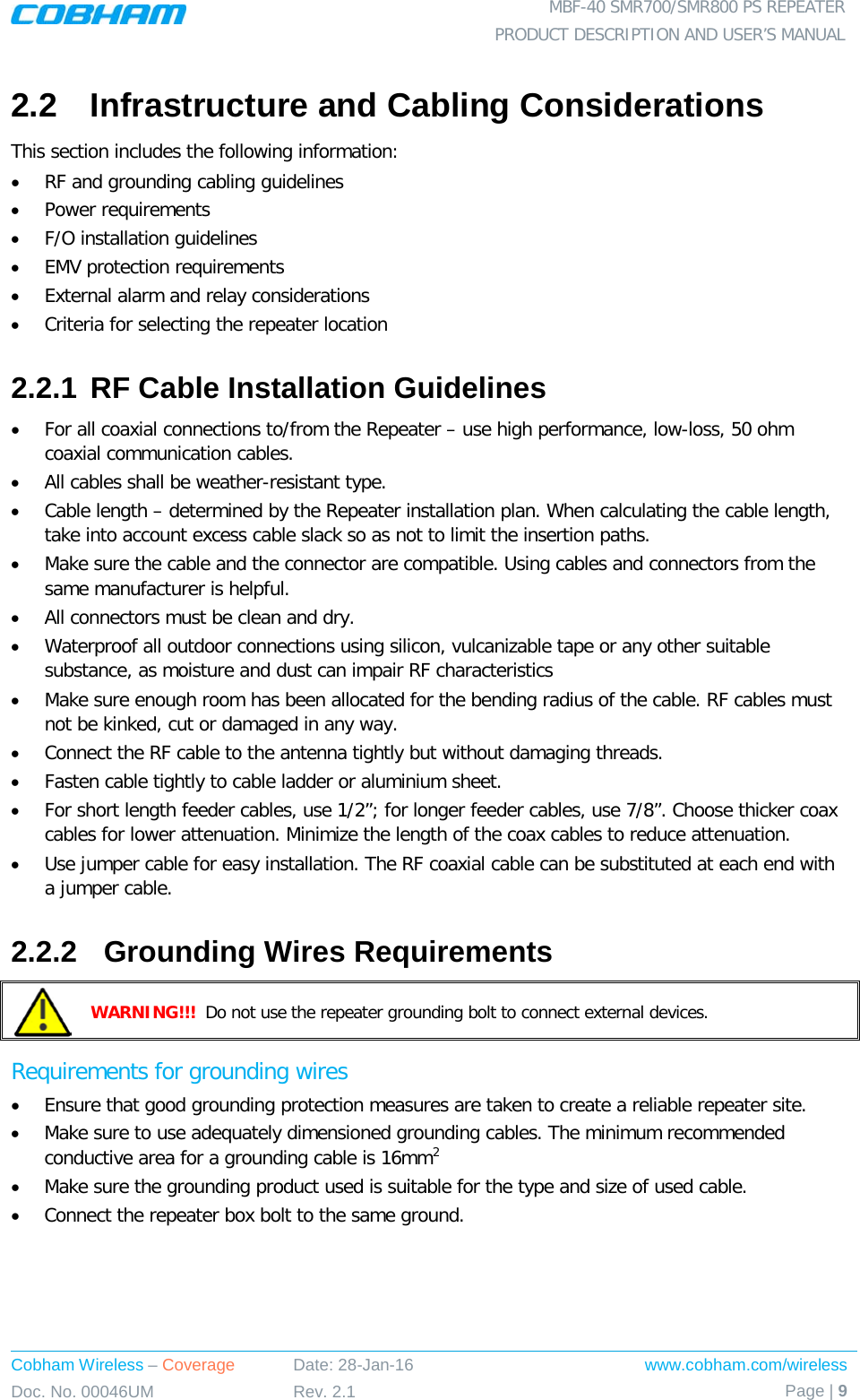
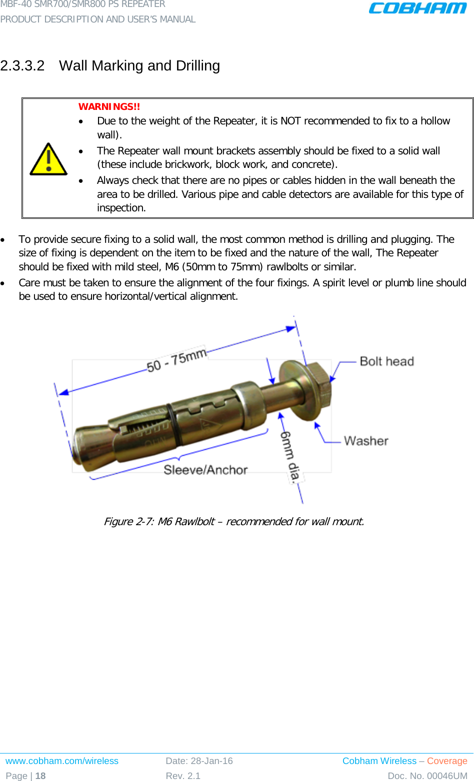
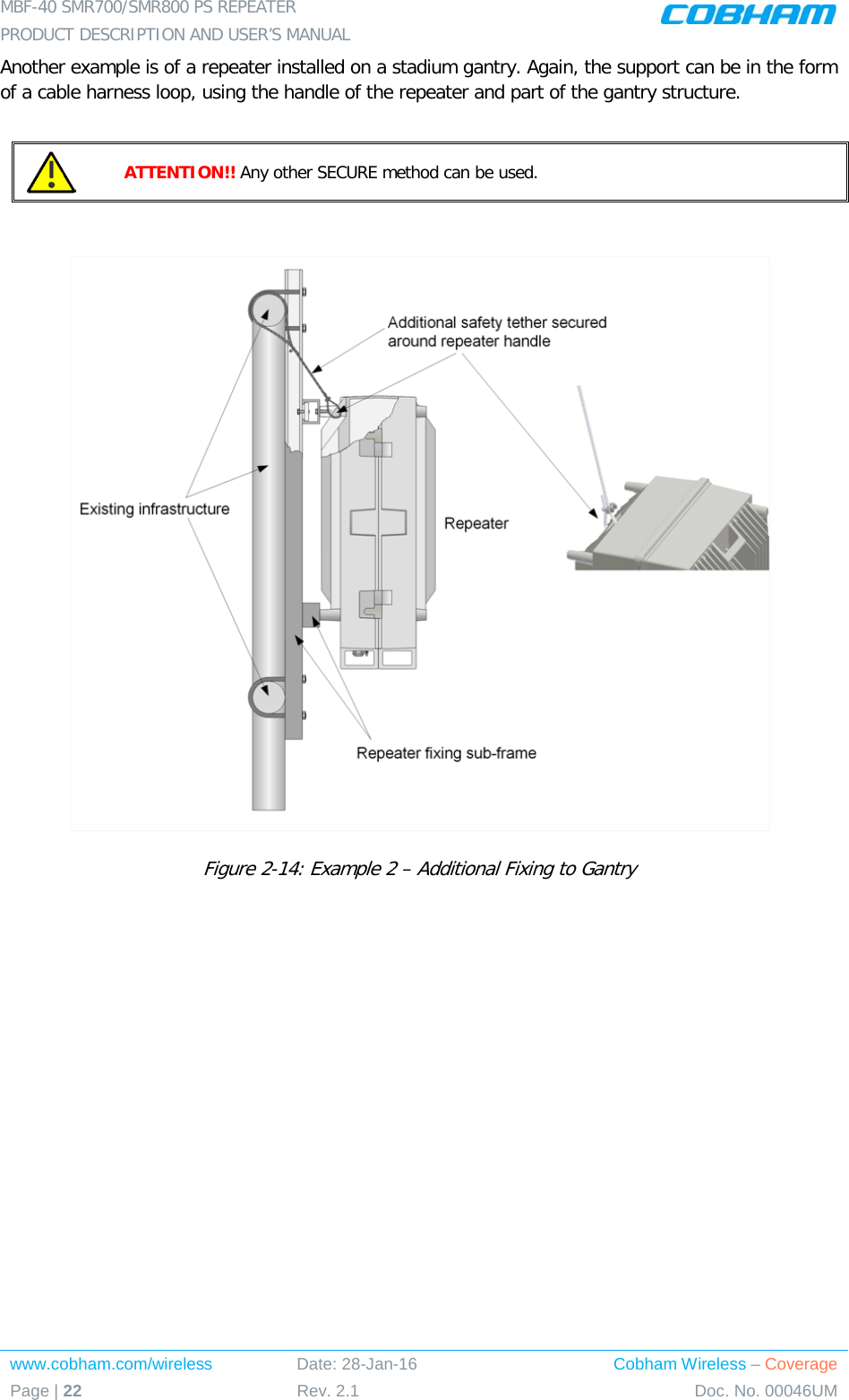
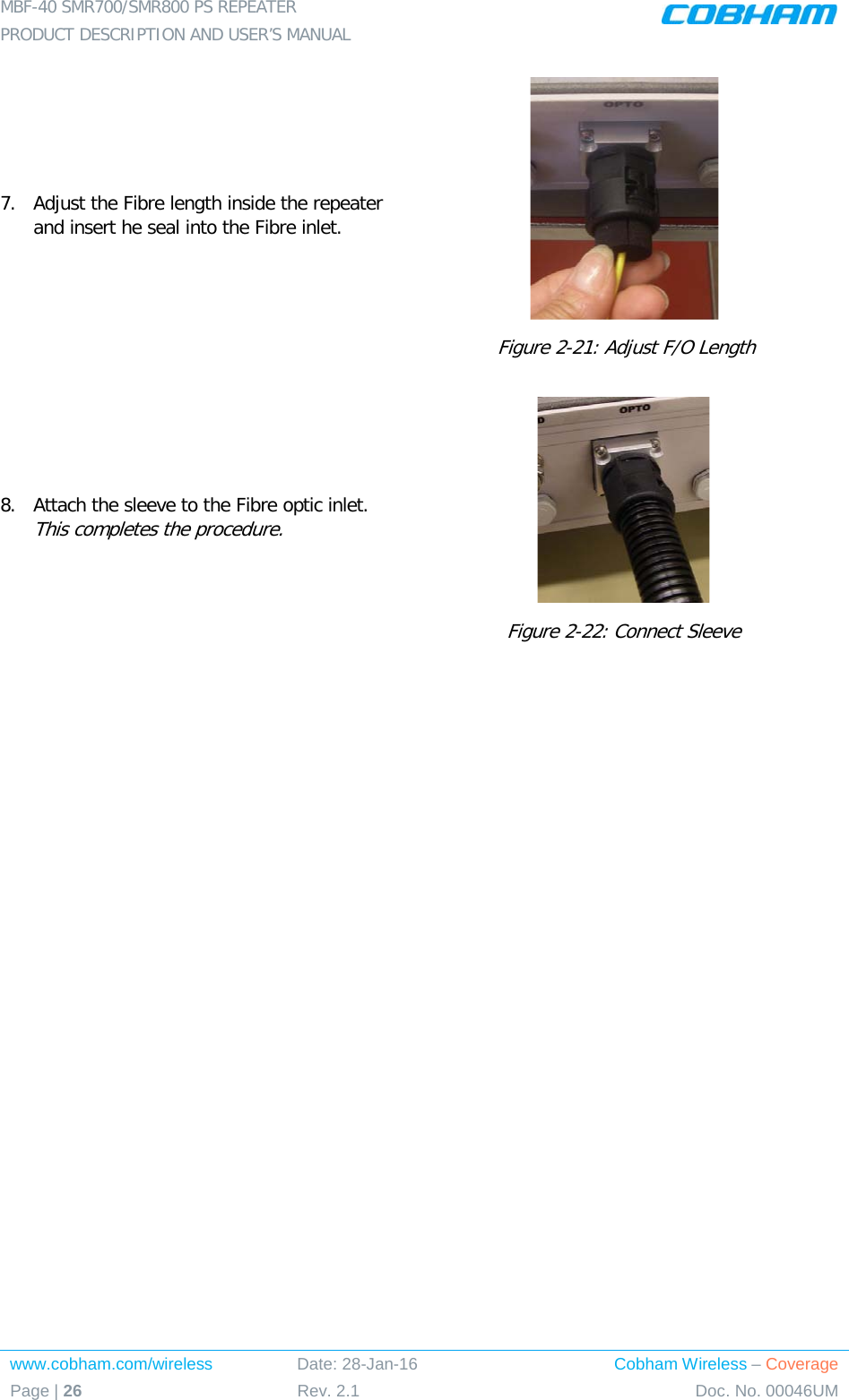
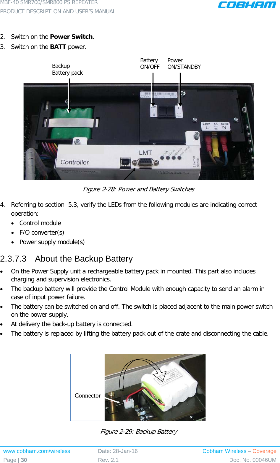
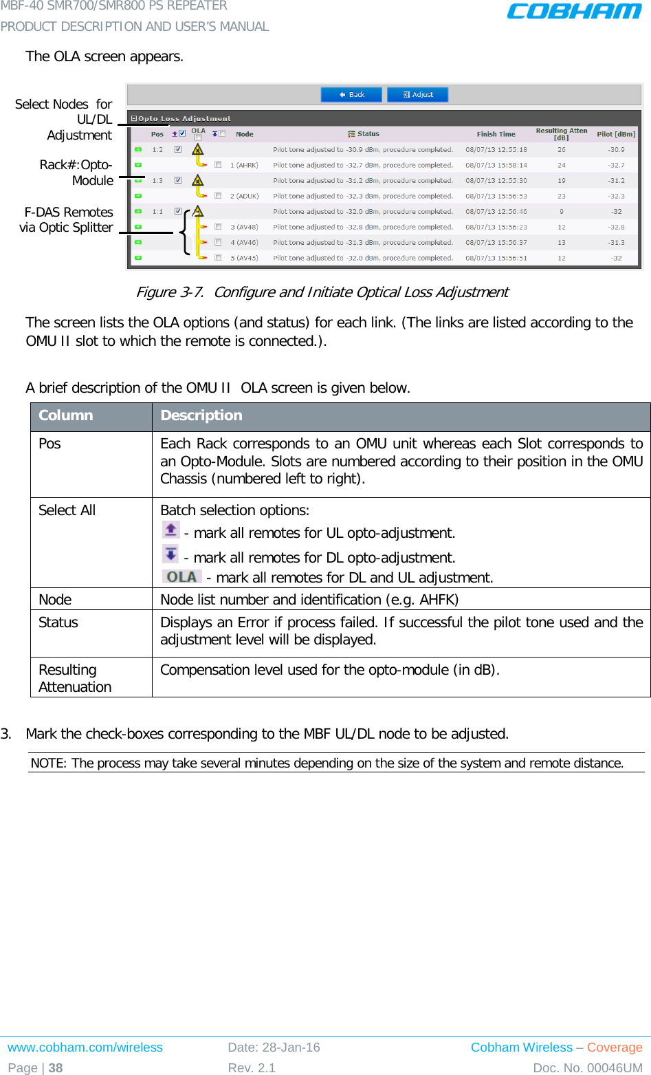
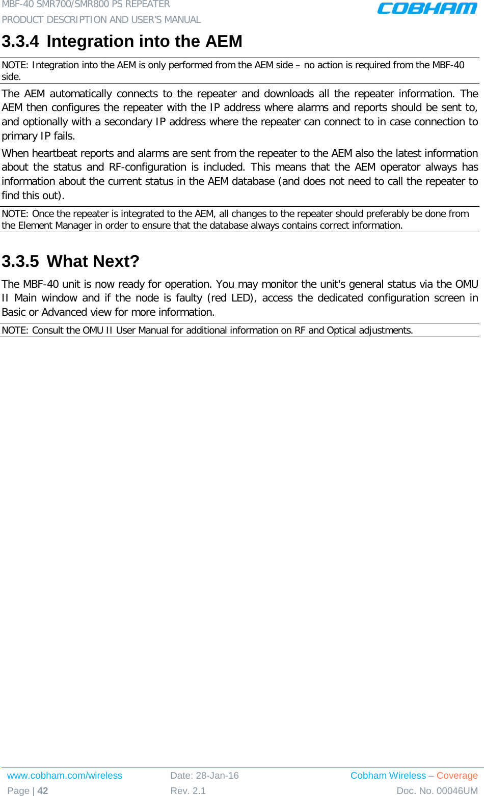
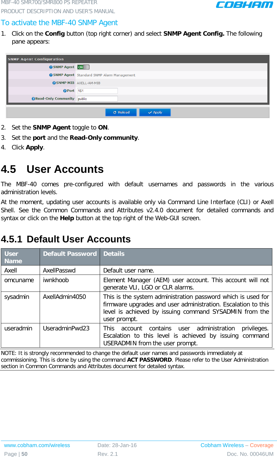
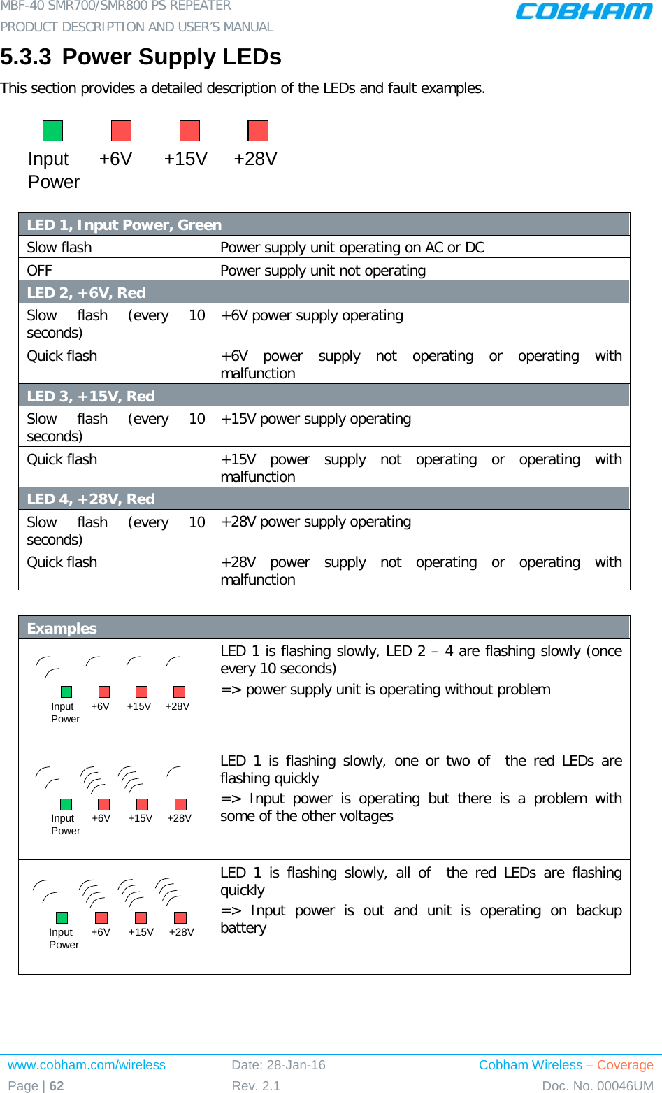
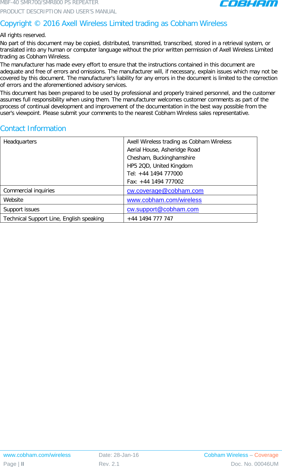
![MBF-40 SMR700/SMR800 PS REPEATER PRODUCT DESCRIPTION AND USER’S MANUAL Cobham Wireless – Coverage Date: 28-Jan-16 www.cobham.com/wireless Doc. No. 00046UM Rev. 2.1 Page | 15 2.3 Repeater Installation 2.3.1 Unpacking Upon receiving the MBF-40 Repeater perform the following: 1. Examine the shipping container for damage before unpacking the unit. 2. Perform a visual inspection to reveal any physical damage to the equipment. 3. Verify that all of the equipment (listed below) is included. Otherwise contact Cobham Wireless. The MBF-40 Repeater is shipped with the following equipment: Package Contents CD containing User’s Manual and USB driver Mounting Brackets Additional (supplied) installation components: Qty. Description 4x M8x12 bolts for securing the Repeater to the brackets 1x Insex tool for bolts 1x Power Cable 1x Fiber Conduit inlet hose fitter (may be pre-assembled) 2 x Sets of keys Optional equipment AC Cable [30 ft.] – Long cable for AC power Alarm Cable [30 ft.] – Long cable for External Alarms Input](https://usermanual.wiki/PBE-Europe-as-Axell-Wireless/A218SERIES/User-Guide-2951792-Page-27.png)