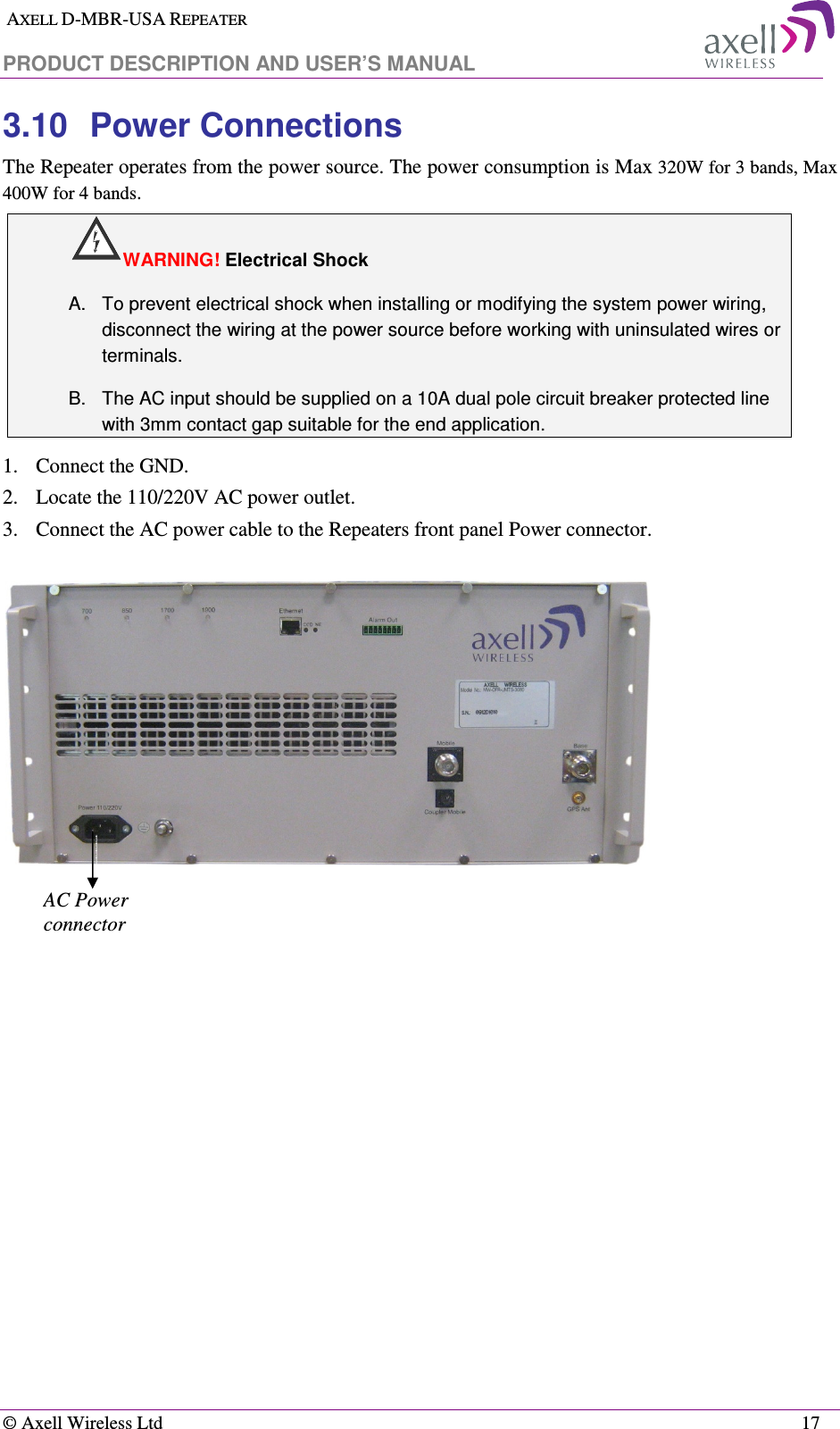
PBE Europe as Axell Wireless DFR-LTE-3380 DR3307 700MHz Booster User Manual Manual
Axell Wireless DR3307 700MHz Booster Manual
UserManual.wiki
>
PBE Europe as Axell Wireless
>
DFR LTE 3380 User Manual
Manual
Navigation menu
Upload a User Manual
Namespaces
Wiki Guide
HTML
PDF
Info
Views
User Manual
Discussion / Help
Navigation
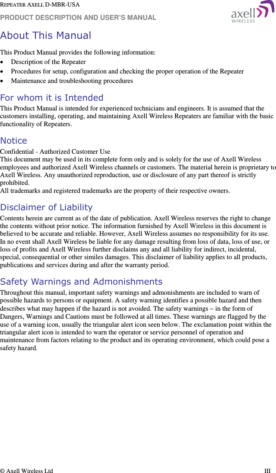
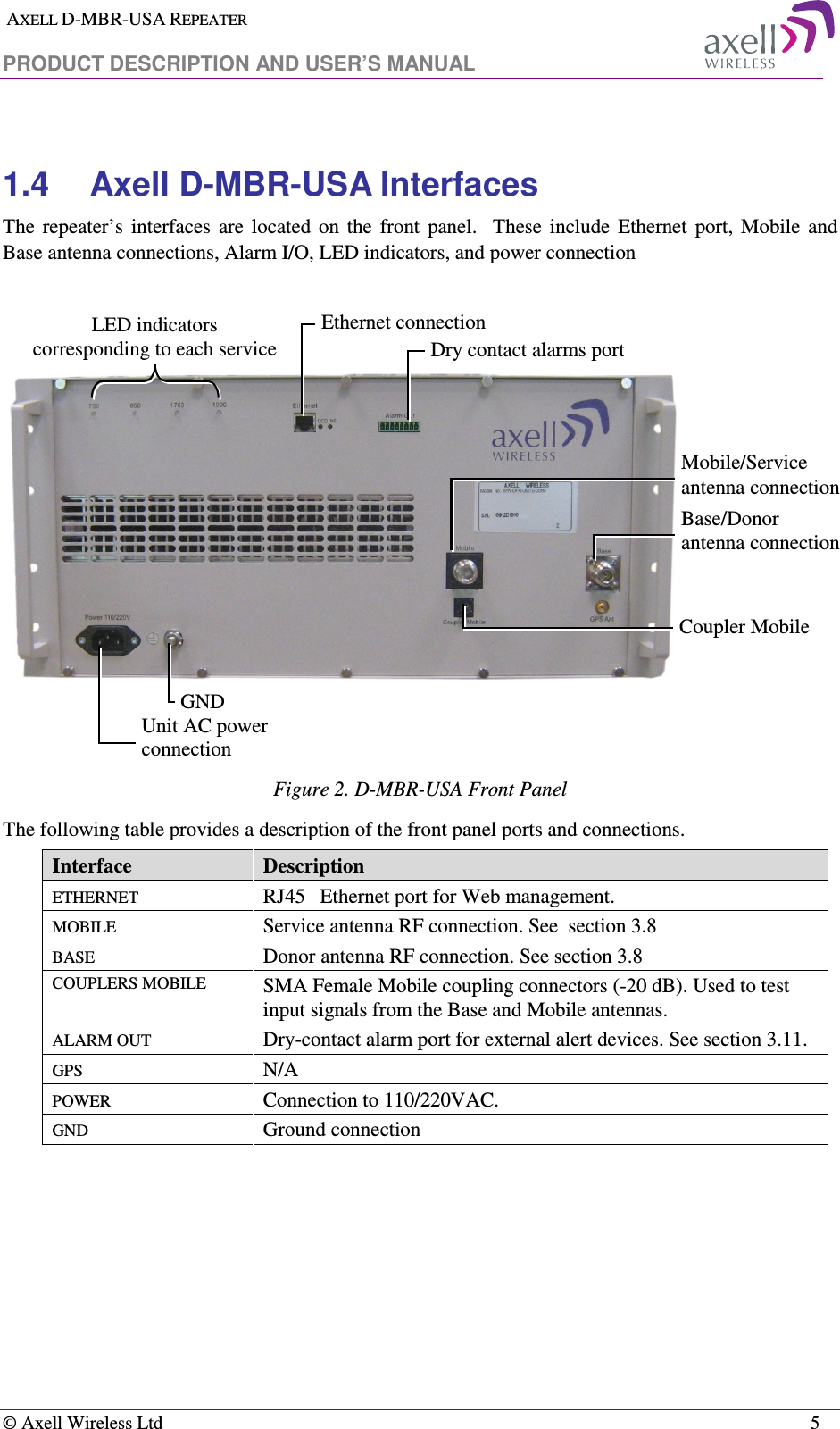
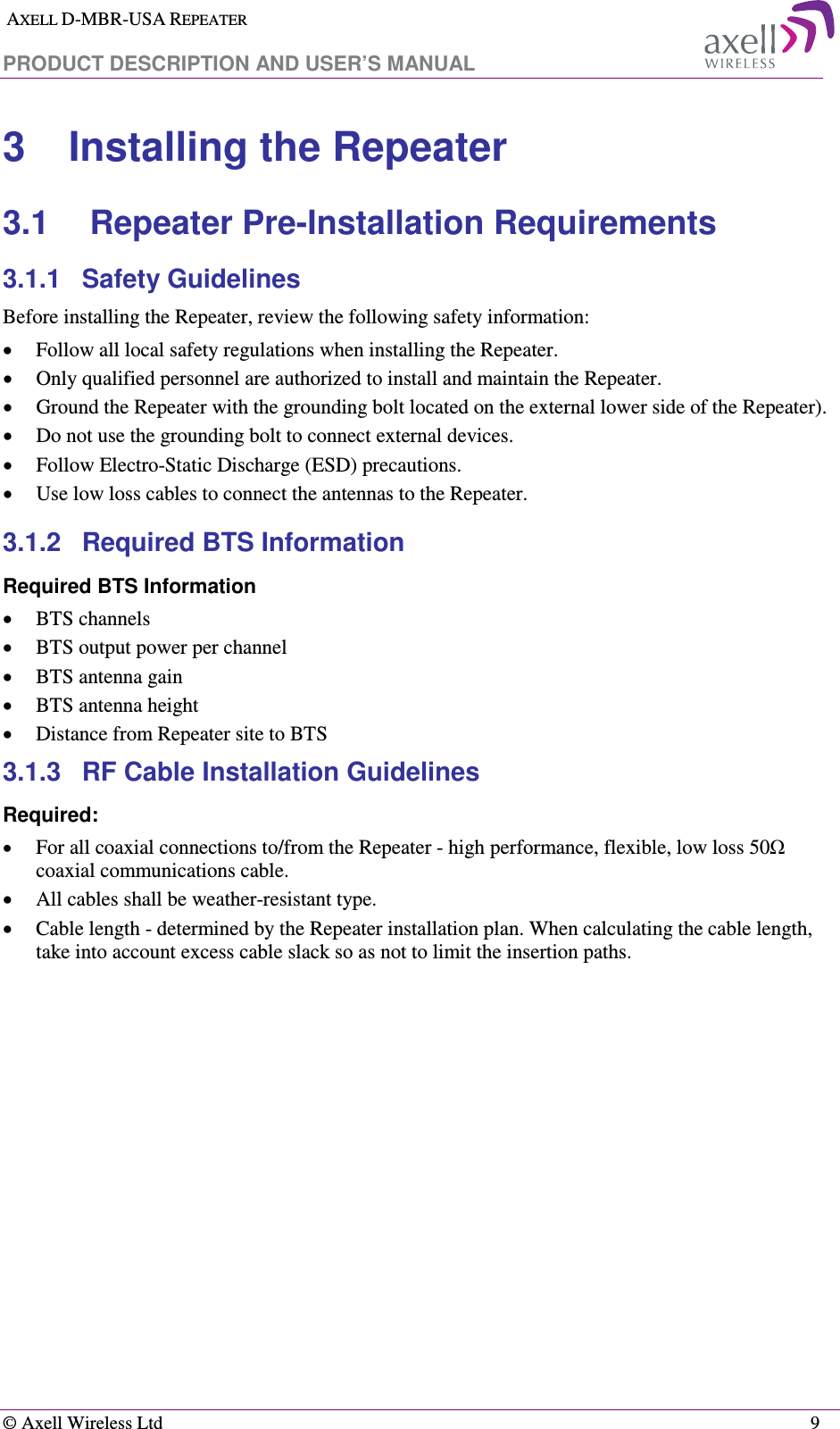
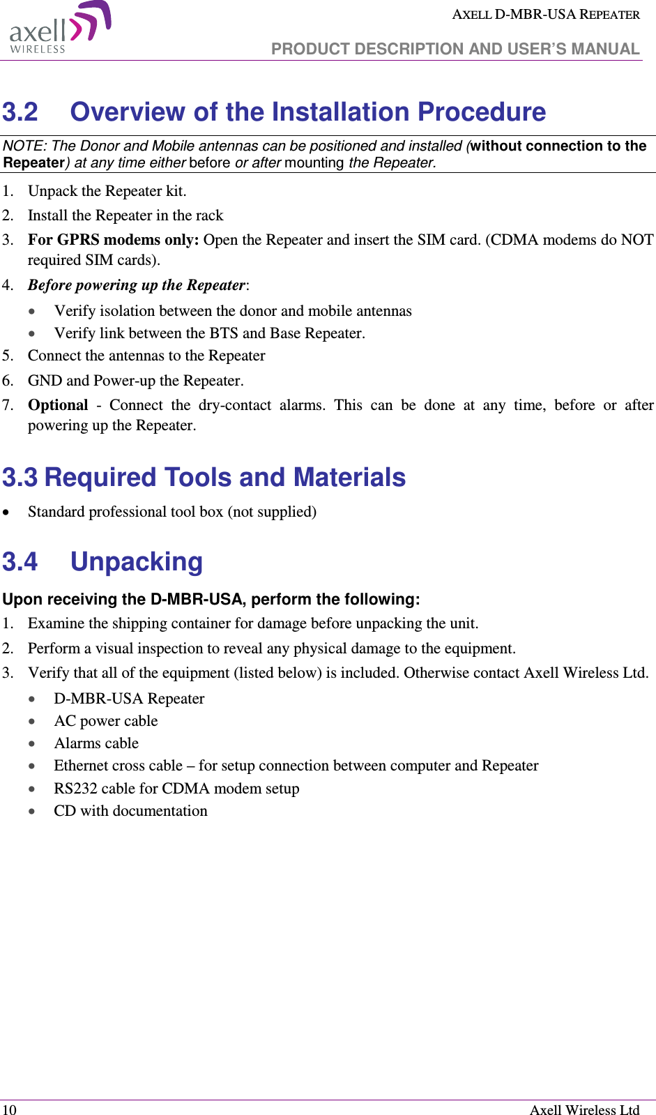
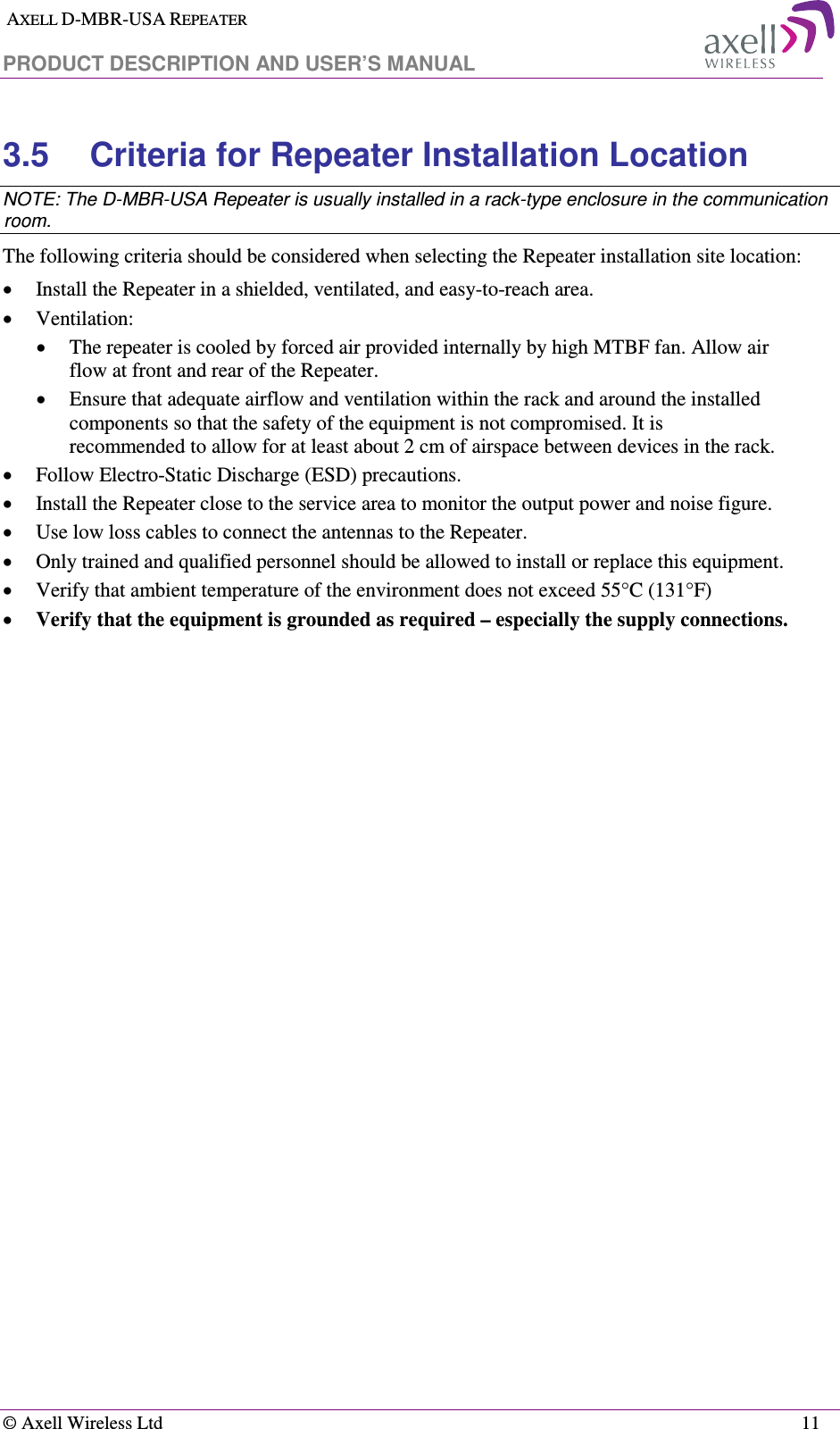
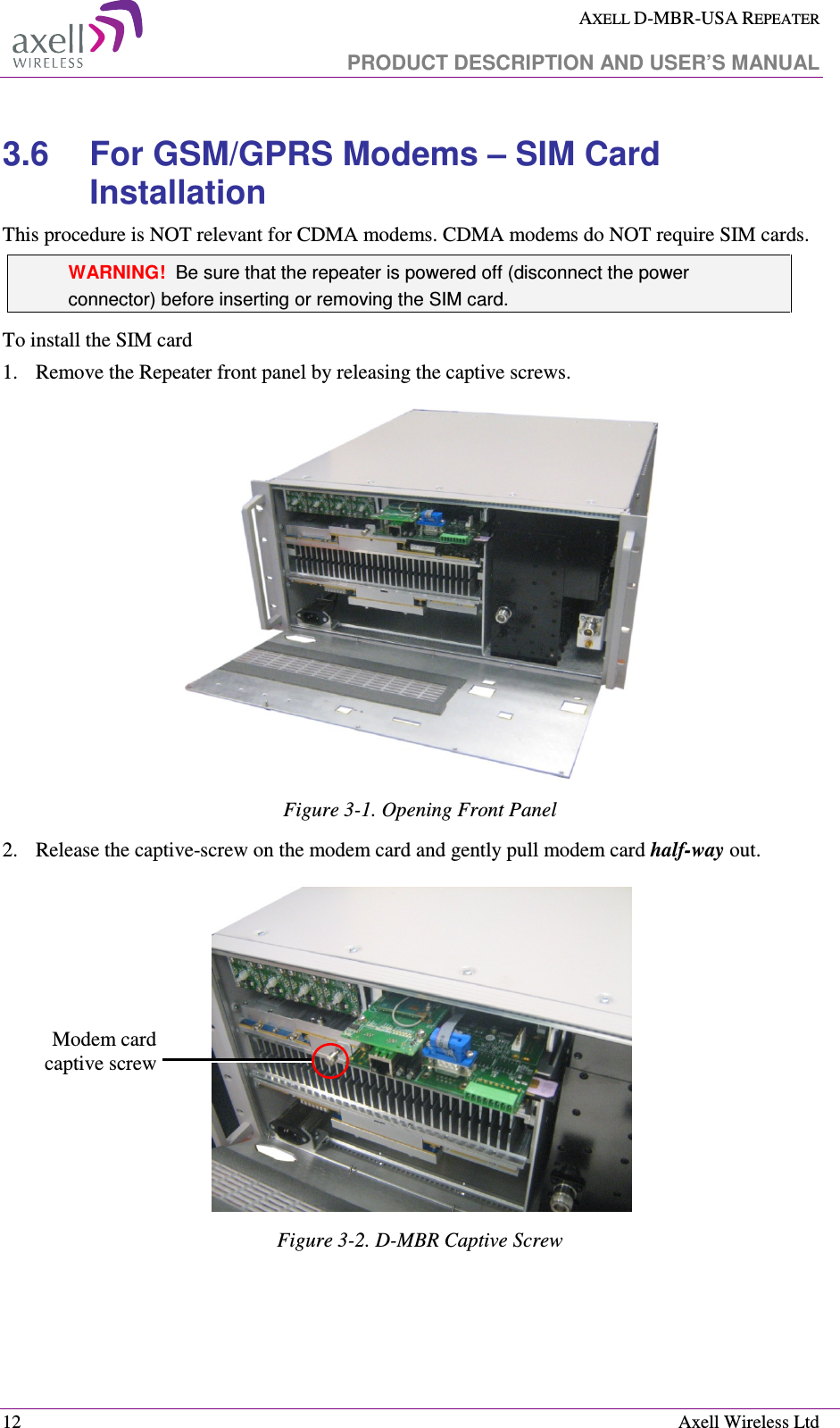
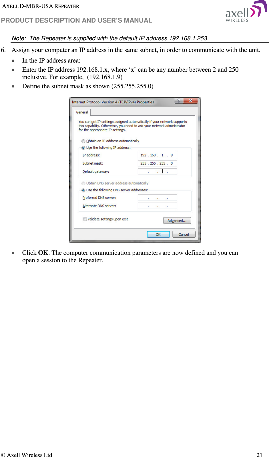
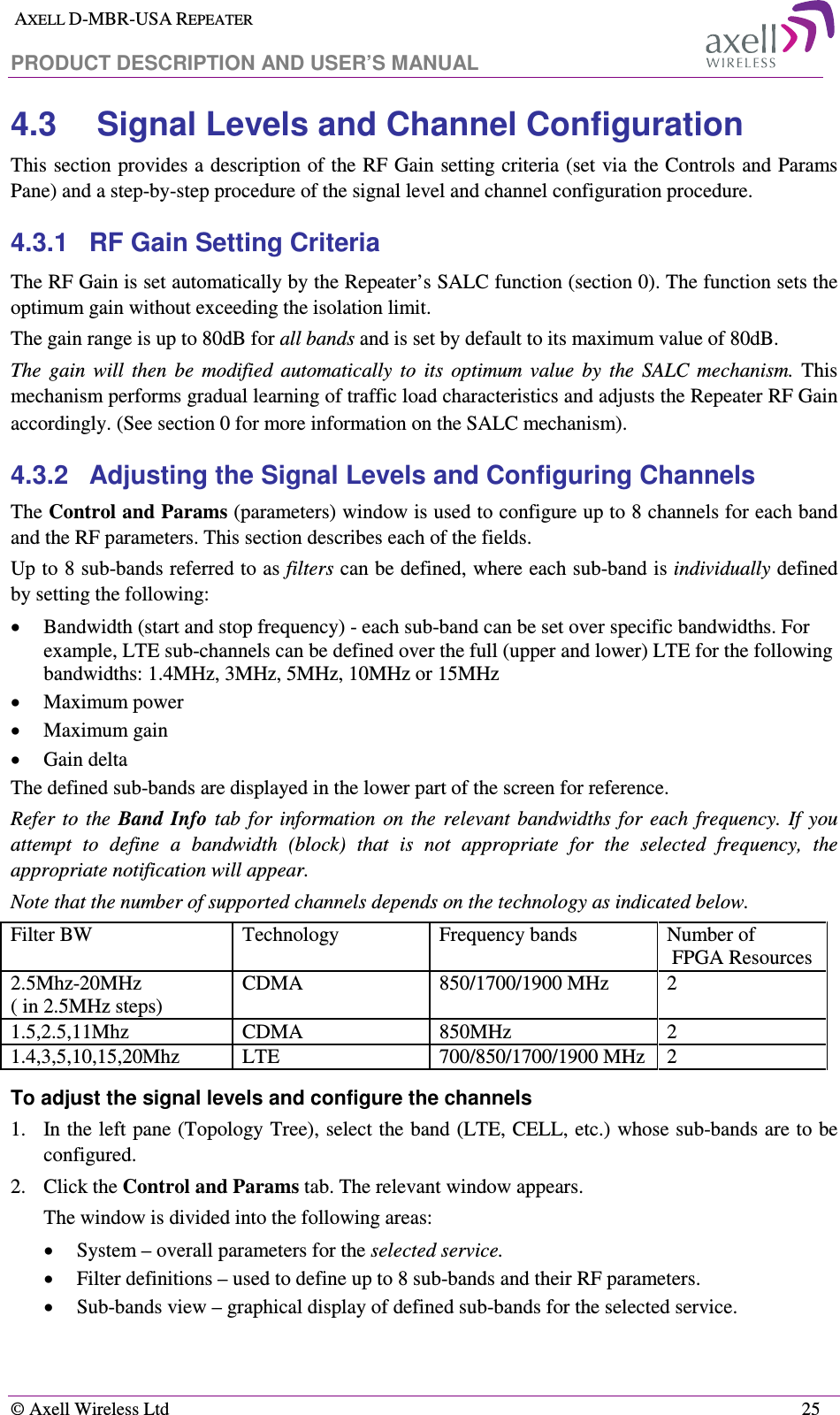
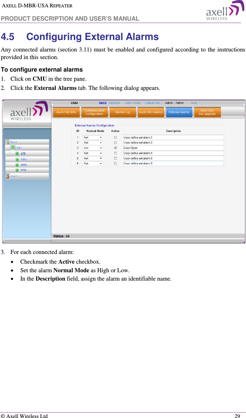
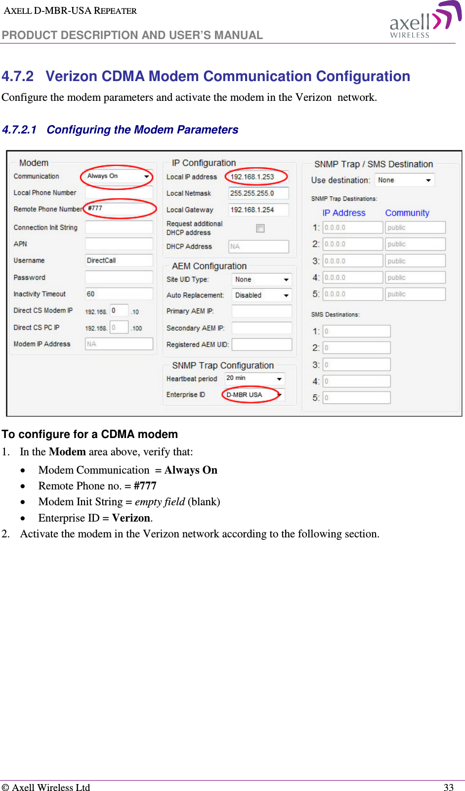
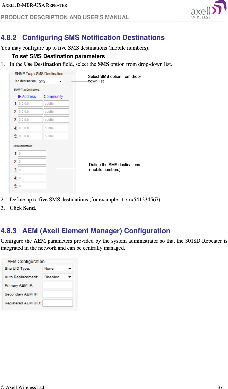
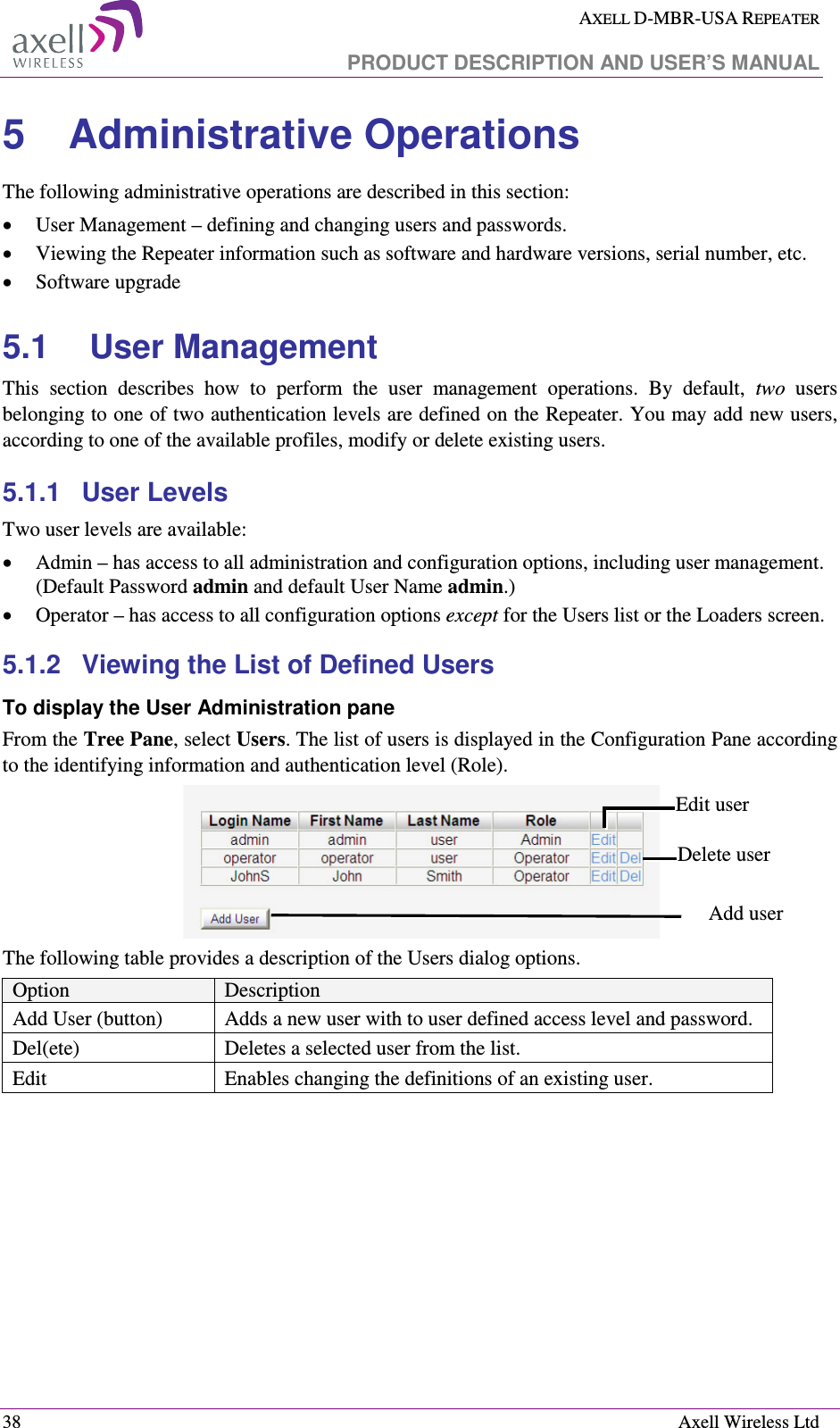
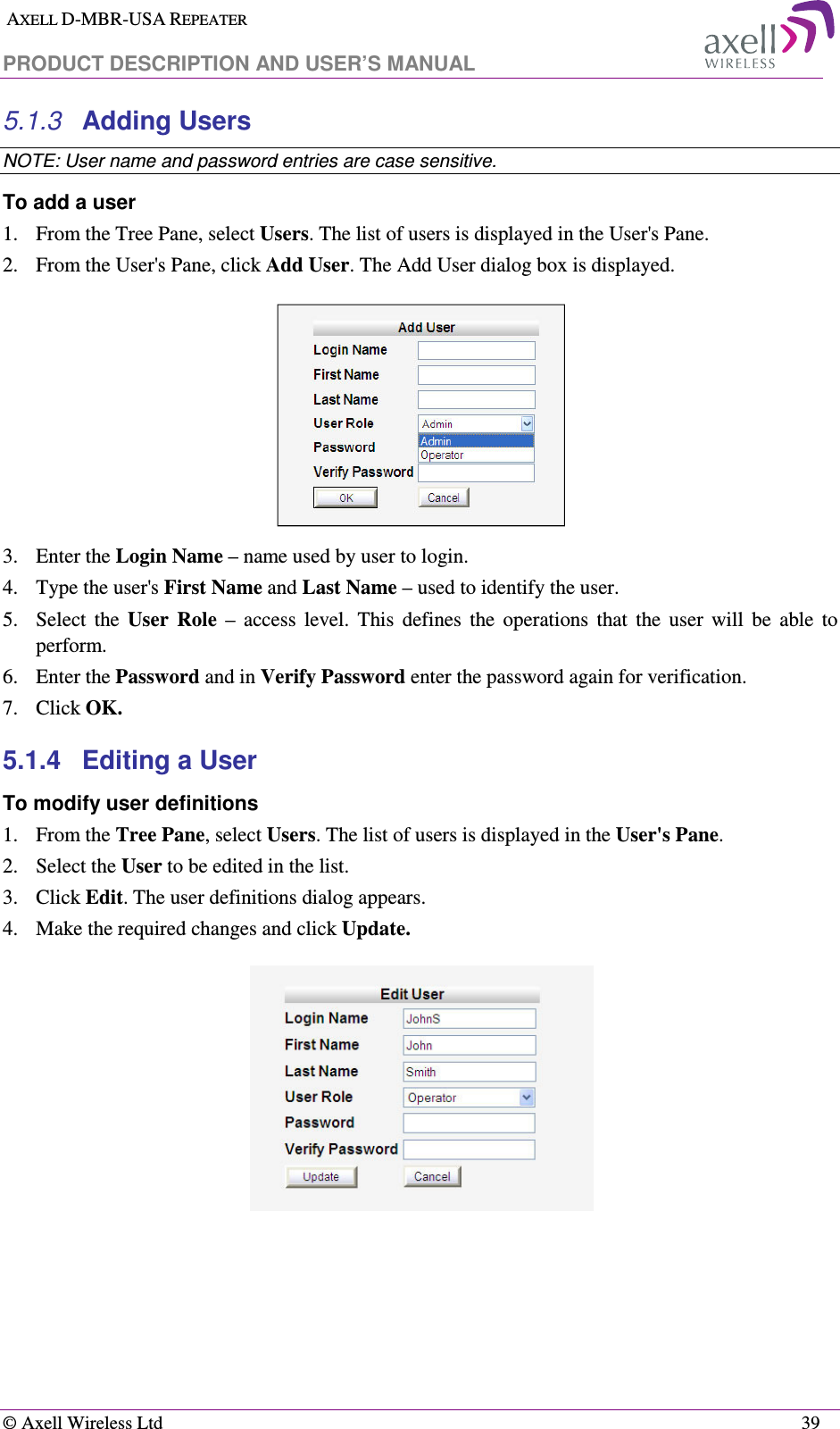
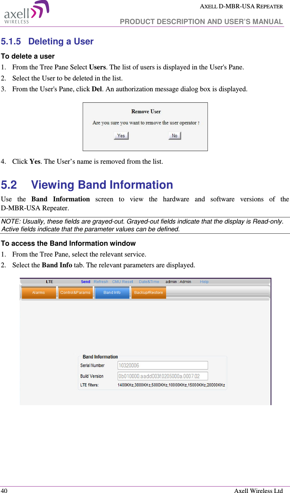
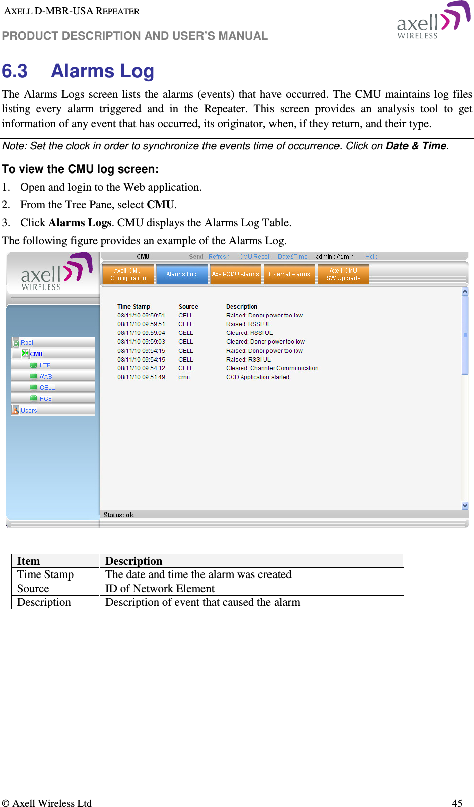
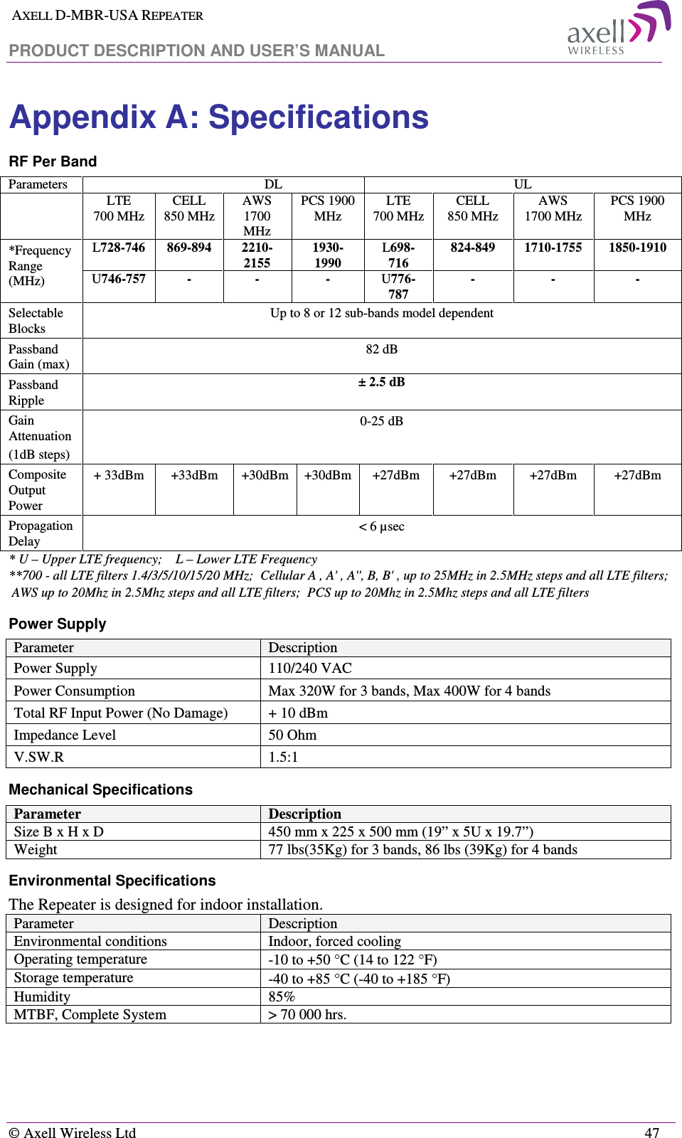
![AXELL D-MBR-USA REPEATER PRODUCT DESCRIPTION AND USER’S MANUAL © Axell Wireless Ltd 3 1.2 Models and Ordering Information Part Number Product Name Service & Frequency [MHz] Supported sub-bands /filter D-MBR-CH DMBR Chassis 4 band D-MBR chassis, power supply, communication card -- D-MBR-CDMA-M DMBR Modem D-MBR CDMA 1X Modem -- D-BM-3307 DMBR 700 33 dBm module 33 dBm, 8 filter 700 LTE module for DMBR 700 - all LTE filters 1.4/3/5/10/15/20 MHz D-BM-3307-12 DMBR 700 33 dBm module 33 dBm, 12 filter 700 LTE module for DMBR 700 - all LTE filters 1.4/3/5/10/15/20 MHz D-BM-3308 DMBR 850 33 dBm module 33dBm, 8 filter 850 Cellular module for DMBR Cellular A , A' , A'', B, B' , up to 25MHz in 2.5MHz steps and all LTE filters; D-BM-3308-12 DMBR 850 27 dBm module 33 dBm, 12 filter 850 Cellular module for DMBR Cellular A , A' , A'', B, B' , up to 25MHz in 2.5MHz steps and all LTE filters; D-BM-3017 DMBR 1700 30 dBm module 30 dBm, 8 filter 1700 AWS module for DMBR AWS up to 20Mhz in 2.5Mhz steps and all LTE filters D-BM-3017-12 DMBR 1700 30 dBm module 30 dBm, 12 filter 1700 AWS module for DMBR AWS up to 20Mhz in 2.5Mhz steps and all LTE filters D-BM-3019 DMBR 1900 30 dBm module 30 dBm, 8 filter 1900 PCS module for DMBR PCS up to 20Mhz in 2.5Mhz steps and all LTE filters D-BM-3019-12 DMBR 1900 30 dBm module 30 dBm, 12 filter 1900 PCS module for DMBR PCS up to 20Mhz in 2.5Mhz steps and all LTE filters D-MBR-9P D-MBR 9 Plexer 9 Plexer to support 700 / 850 / AWS / PCS for DMBR 700 / 850 / 1700 / 1900 D-MBR-7P-7-8-19 D-MBR 7 Plexer 7 Plexer to support 700 / 850 / PCS for DMBR 700 / 850 / 1900 D-MBR-7P-7-8-17 D-MBR 7 Plexer 7 Plexer to support 700 / 850 / AWS for DMBR 700 / 850 / 1700 D-MBR-7P-7-17-19 D-MBR 7 Plexer 7 Plexer to support 700 / PCS /AWS for DMBR 700/1700/1900](https://usermanual.wiki/PBE-Europe-as-Axell-Wireless/DFR-LTE-3380/User-Guide-1587038-Page-9.png)
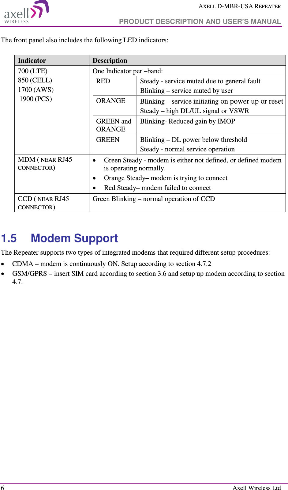
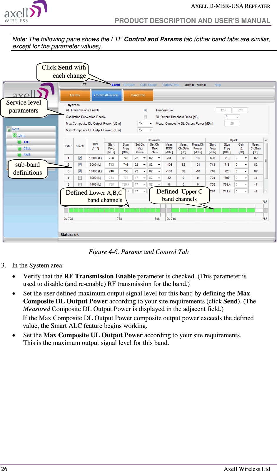
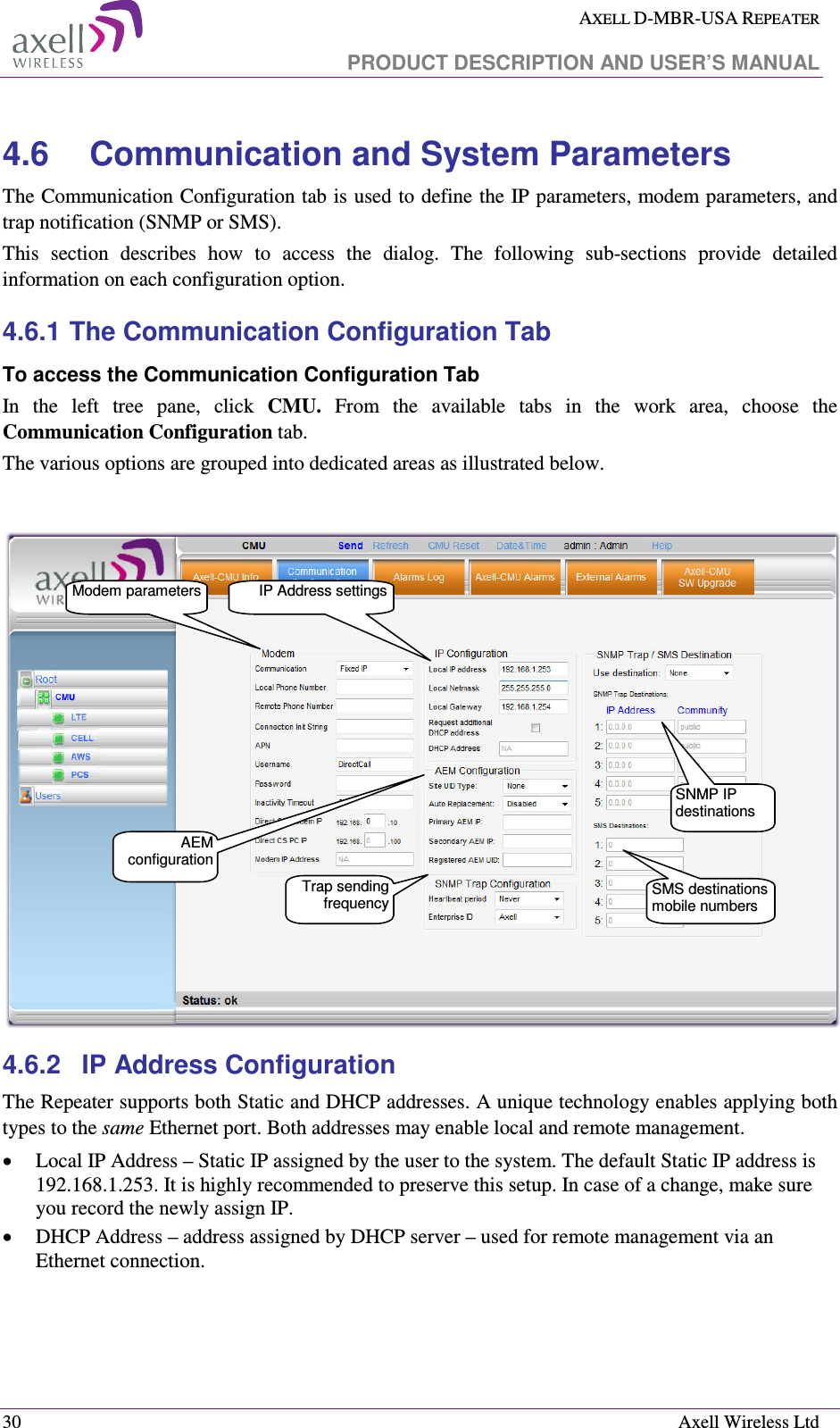
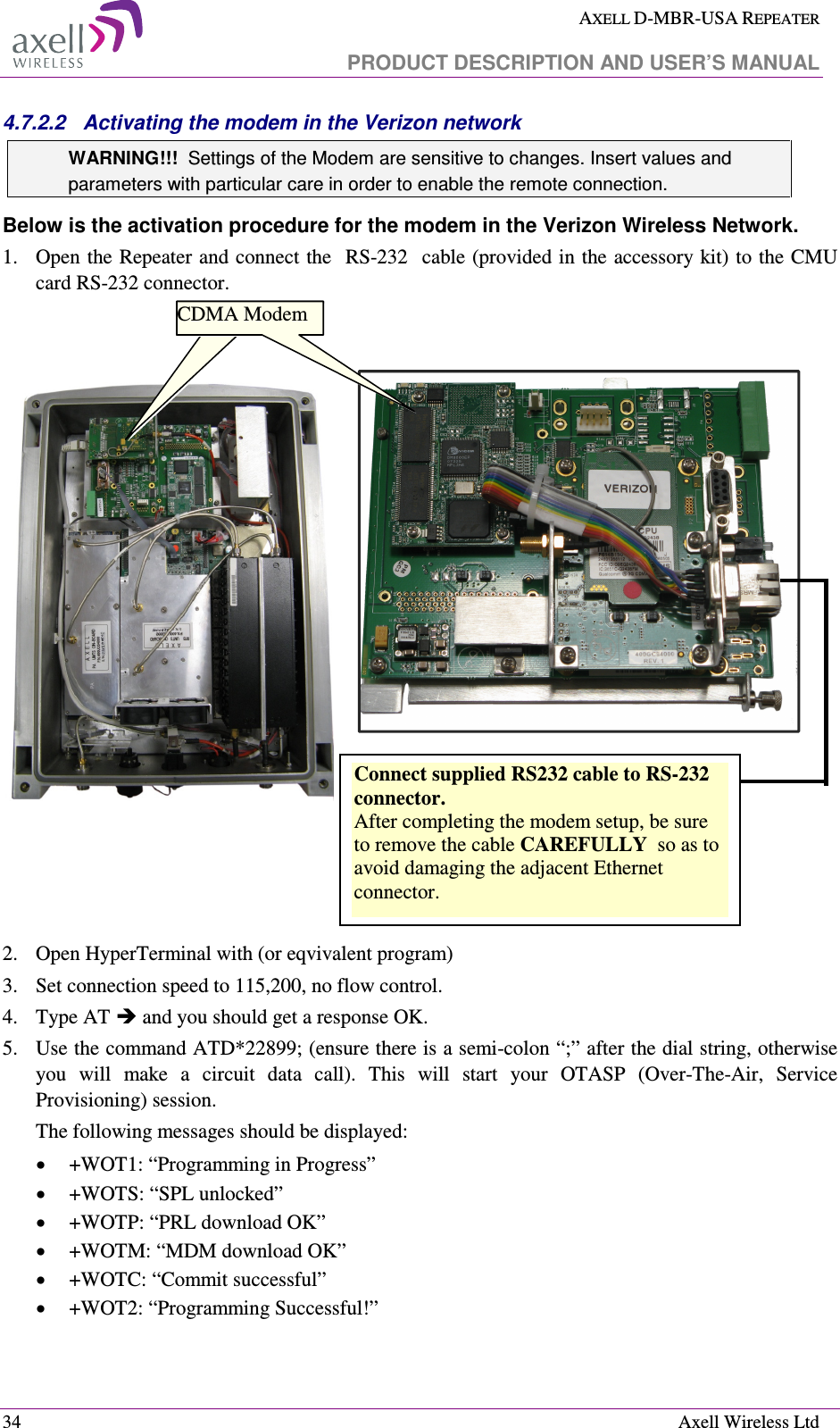
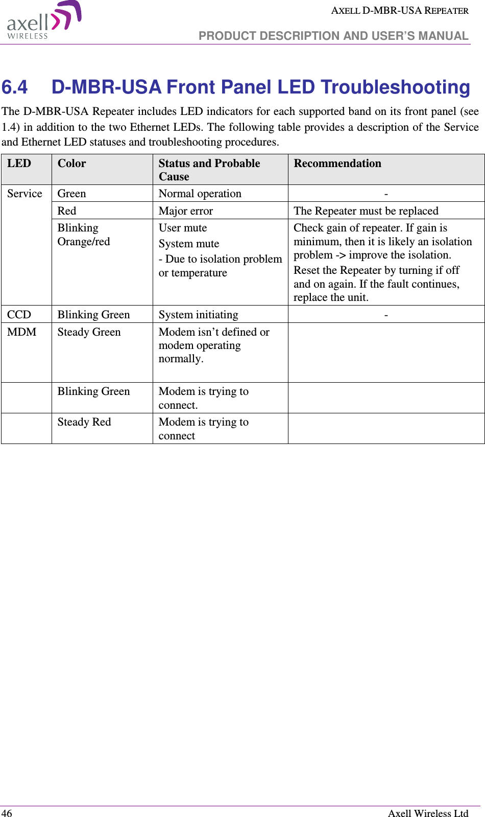
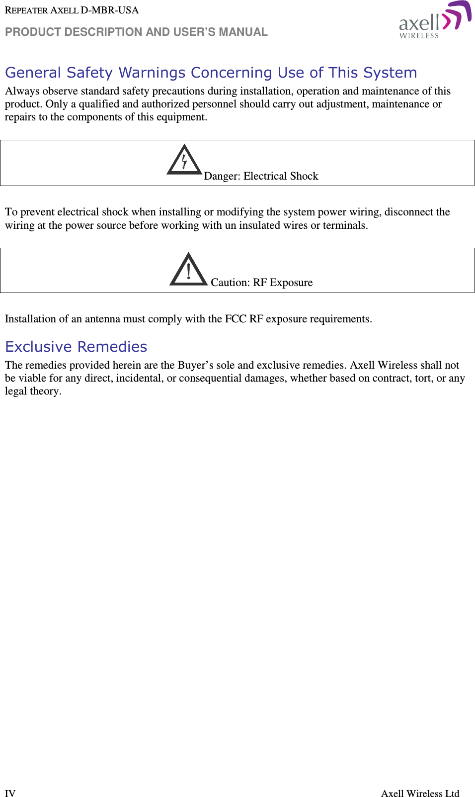
![AXELL D-MBR-USA REPEATER PRODUCT DESCRIPTION AND USER’S MANUAL 4 Axell Wireless Ltd Part Number Product Name Service & Frequency [MHz] Supported sub-bands /filter D-MBR-6P D-MBR 6 Plexer 6 Plexer to support 850 / AWS / PCS for DMBR 850 / 1700 / 1900 D-MBR-5P-7-19 D-MBR 5 Plexer 5 Plexer to support 700 / PCS for DMBR 700 / 1900 D-MBR-5P-7-8 D-MBR 5 Plexer 5 Plexer to support 700 / 850 for DMBR 700 / 850 D-MBR-4P-8-19 D-MBR 4 Plexer 4 Plexer to support 850 / PCS for DMBR 850 / PCS D-MBR-3P-7 D-MBR 3 Plexer 3 Plexer to support 700 only for DMBR 700 D-MBR-2P -8 D-MBR 2 Plexer 2 Plexer to support 850 for D-MBR 850 D-MBR-2P -17 D-MBR 2 Plexer 2 Plexer to support AWS for D-MBR 1700 D-MBR-2P -19 D-MBR 2 Plexer 2 Plexer to support PCS for D-MBR 1900 D-MBR-WM-AK D-MBR AK Wall mount accessory kit for DMBR 1.3 Smart-ALC Function The Smart Automatic Level Control (Smart-ALC) is an innovative algorithm for automatic repeater gain adjustment. Combined with advanced control algorithms, SALC is capable of learning the traffic load characteristics and adjusting the Repeater RF Gain to the desired value. Smart ALC eliminates the need to perform initial settings for maximal traffic load conditions and on-site gain adjustments. Smart-ALC maintains the Uplink/Downlink gain balance for system transparency. In addition, Smart-ALC prevents oscillations that may occur due to insufficient isolation while maintaining the gain in a linear range operation by adjusting the repeater paths’ gain accordingly. IMOP (Isolation Measurement and Oscillation Prevention) algorithm effectively reduces oscillation problems. The repeater’s power amplifier includes power-monitoring circuits with Automatic Level Control (ALC) that prevents excessive output power while maintaining the power amplifier linearity.](https://usermanual.wiki/PBE-Europe-as-Axell-Wireless/DFR-LTE-3380/User-Guide-1587038-Page-10.png)