PBE Europe as Axell Wireless DMBA30073008PS Class A Booster User Manual
Axell Wireless Class A Booster
UserManual.wiki
>
PBE Europe as Axell Wireless
>
DMBA30073008PS User Manual
>
User manual
Contents
1.
User manual
2.
Revised Users manual
3.
Revision2 of User manual
User manual
Navigation menu
Upload a User Manual
Namespaces
Wiki Guide
HTML
PDF
Info
Views
User Manual
Discussion / Help
Navigation
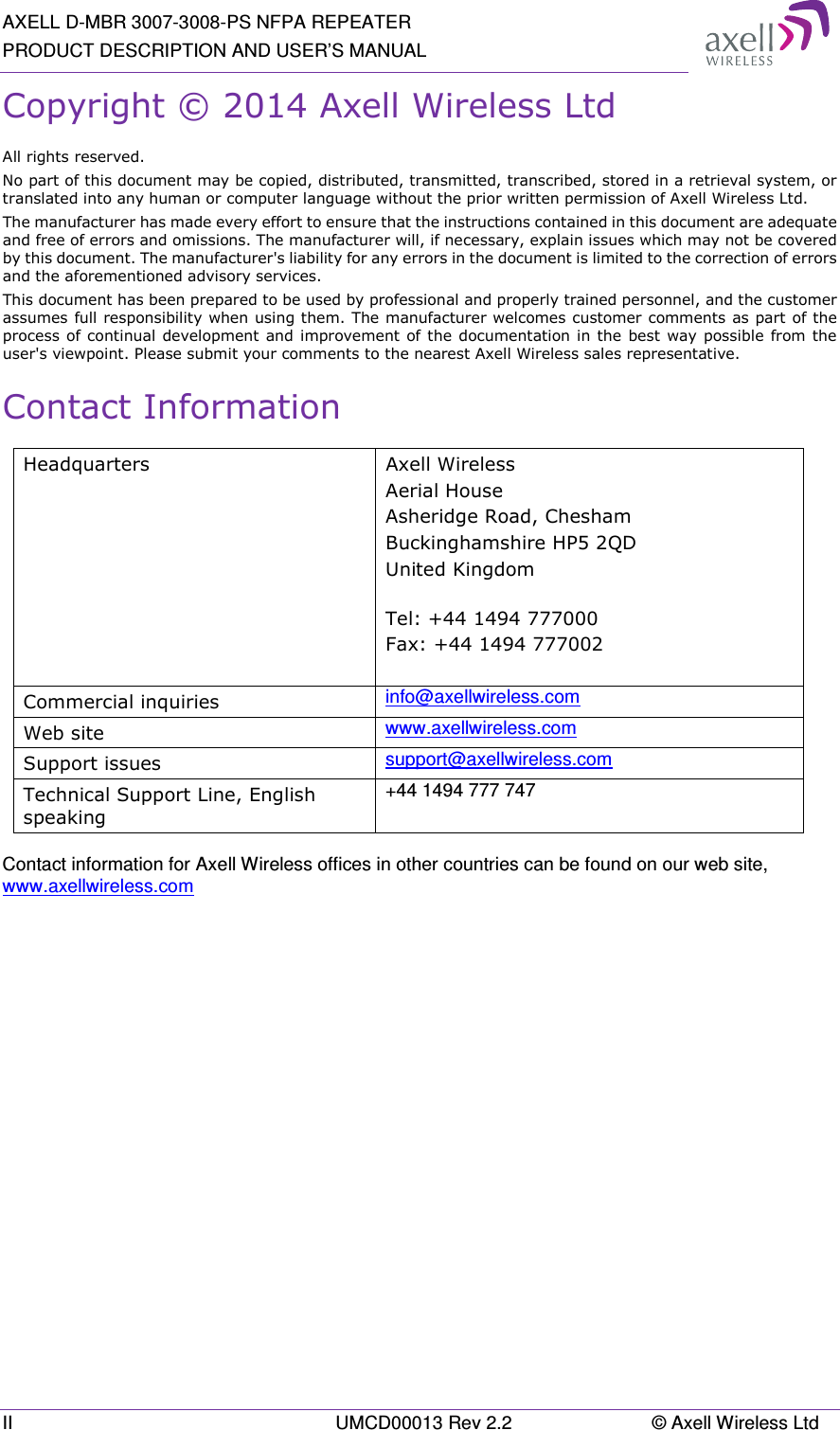
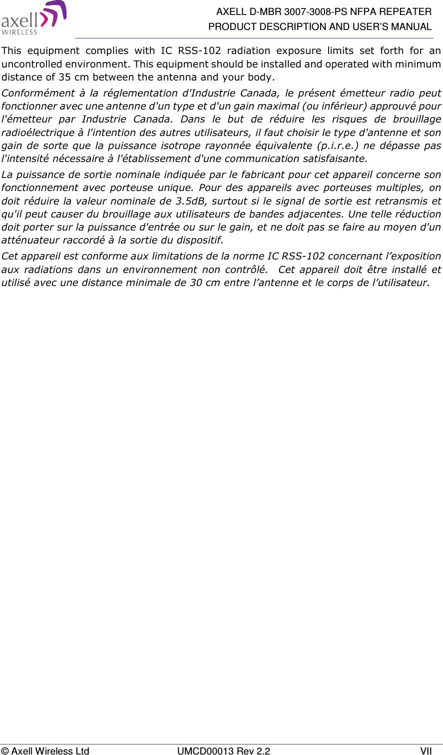
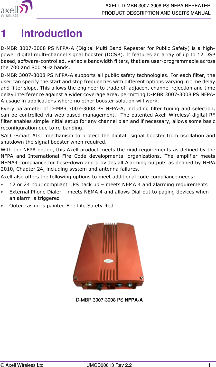
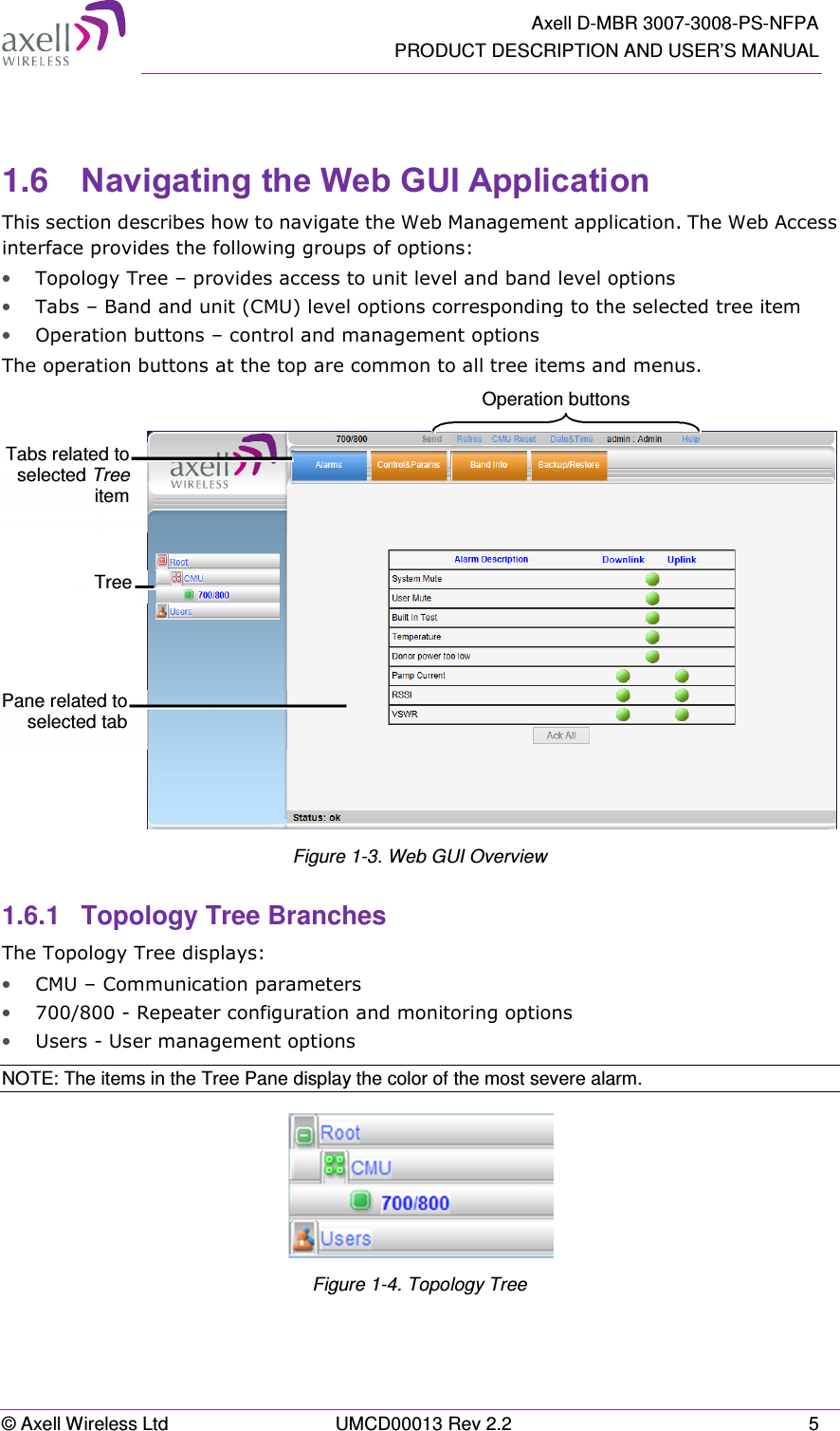
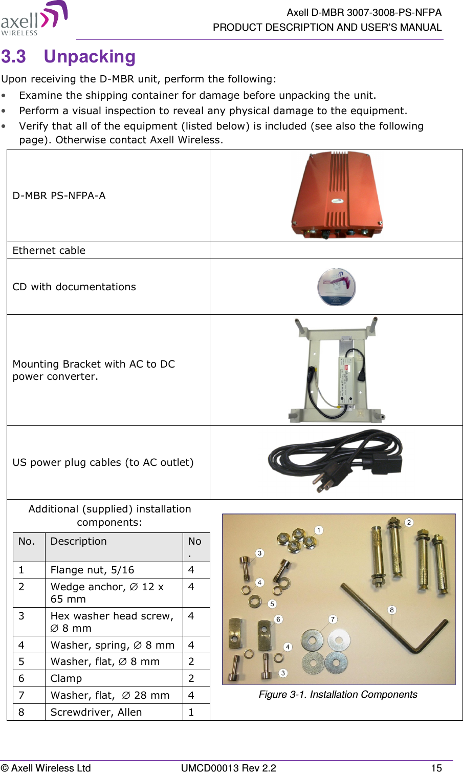
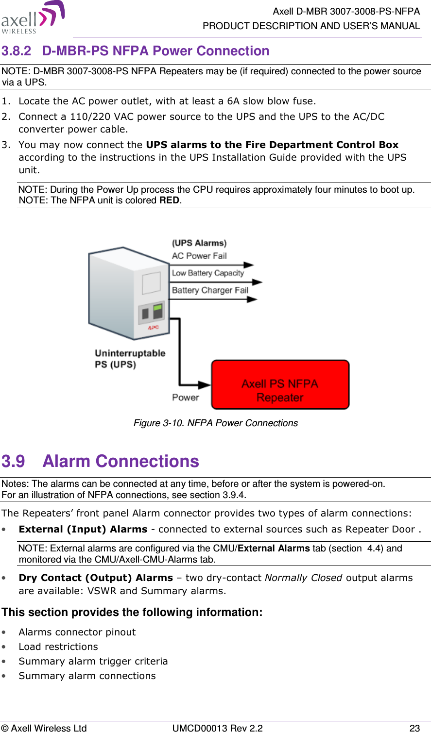
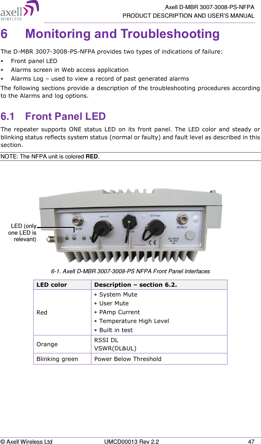
![AXELL D-MBR 3007-3008-PS NFPA REPEATER PRODUCT DESCRIPTION AND USER’S MANUAL © Axell Wireless Ltd UMCD00013 Rev 2.2 V Only for in-building applications One must be aware that FCC regulation mandate that this repeater is to be used only for in-building applications and thus feed passive or active DAS (Distributed Antenna Systems) accordingly. FCC RF Exposure Limits This unit complies with FCC RF exposure limits for an uncontrolled environment. This equipment can only be installed in in-building applications, driving passive or active DAS systems. All antennas must be operated at a minimum distance of 35 cm between the radiator and any person’s body. Antenna Installation Installation of an antenna must comply with the FCC RF exposure requirements. The antenna used for this transmitter must be mounted on permanent structures. The FCC regulation mandate that the EIRP of type B signal boosters should not exceed 5W. Therefore the max antenna gain allowed for this type of signal booster should be limited to the values given by equation (1) for the service antenna and equation (2) for the donor antenna Equation (1) - Max SERVICE antenna gain Max SERVICE antenna gain (dBi) = 37dBm[EIRP] – (33dbi – 10log(N)(dB) – cable loss in dB). For example: No. of Antennas Cable Losses Max Allowed Antenna Gain 4 2 37 - (33+6-2) = 0 dBd 1 2 37- (33+0-2) = 6 dBd 10 2 37- (33+10-2) = -2dBd Note :0dBd = 2.15dBi Equation (2) - Max DONOR antenna gain Max DONOR antenna gain (dBi) = 37 – (27dbi - cable losses in dbi).](https://usermanual.wiki/PBE-Europe-as-Axell-Wireless/DMBA30073008PS.User-manual/User-Guide-2452421-Page-5.png)
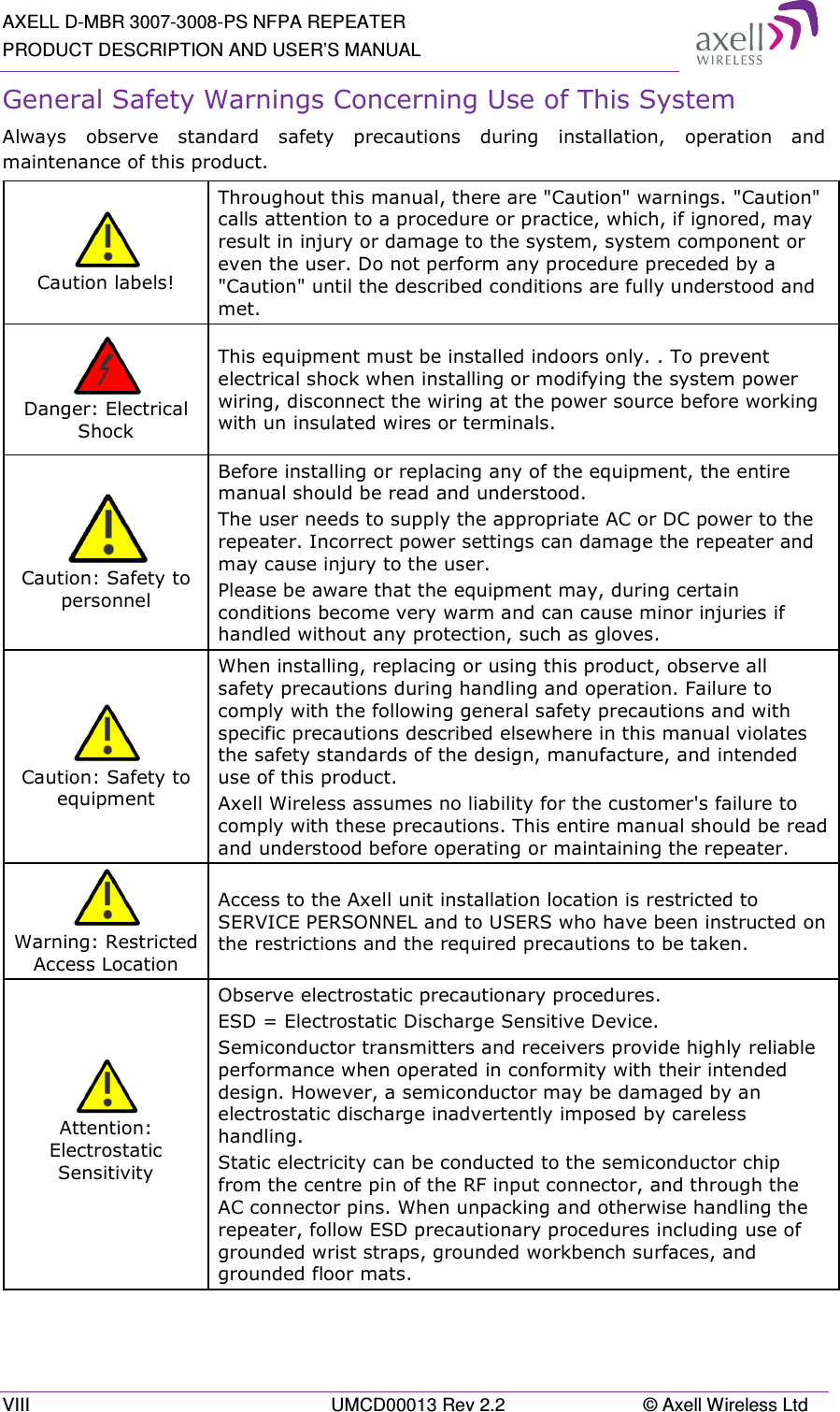
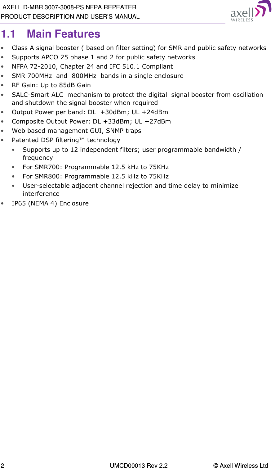
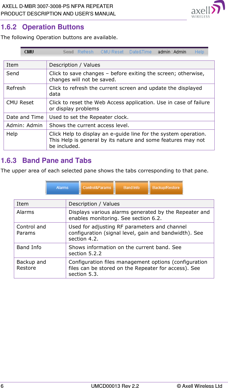
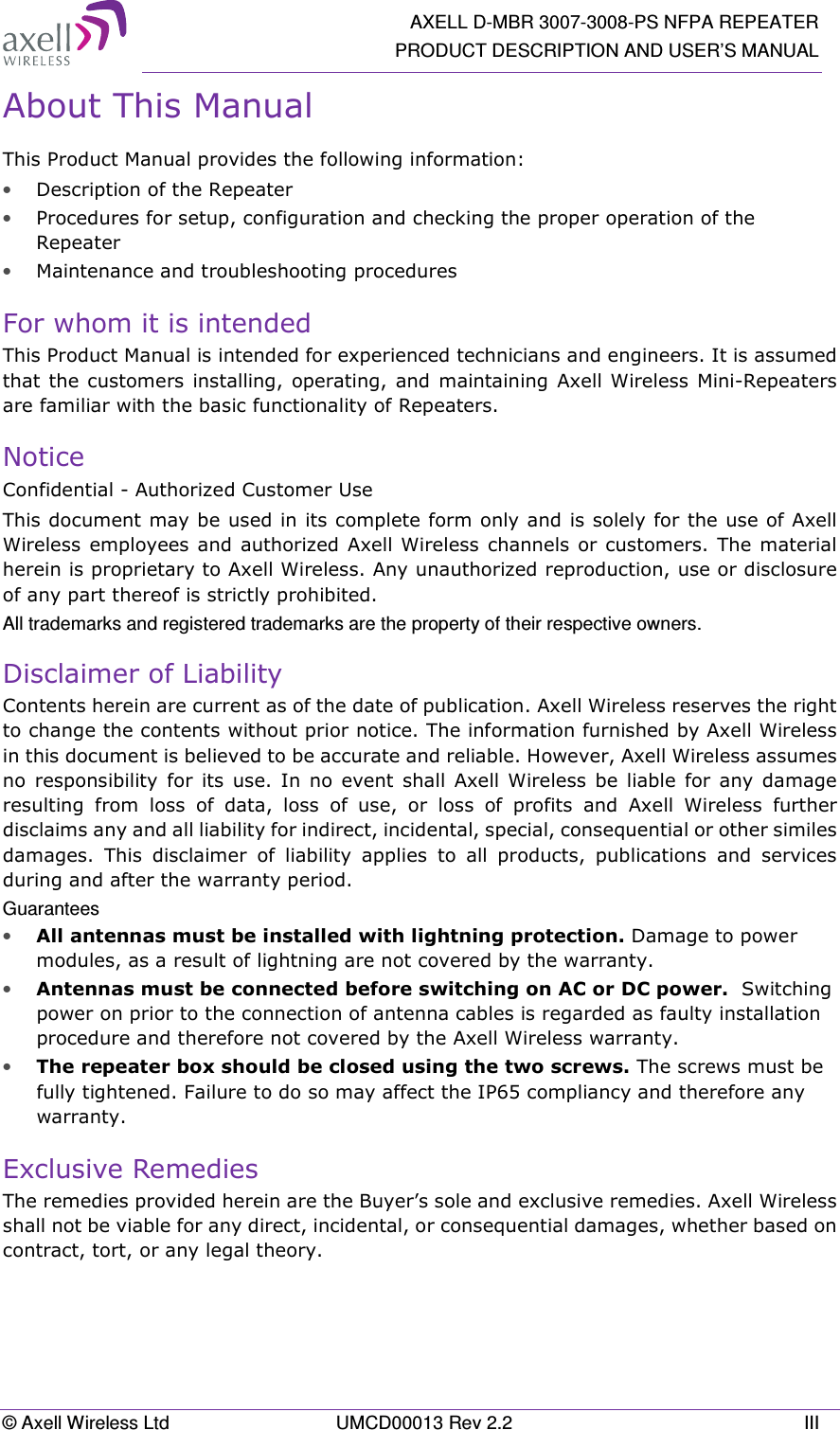
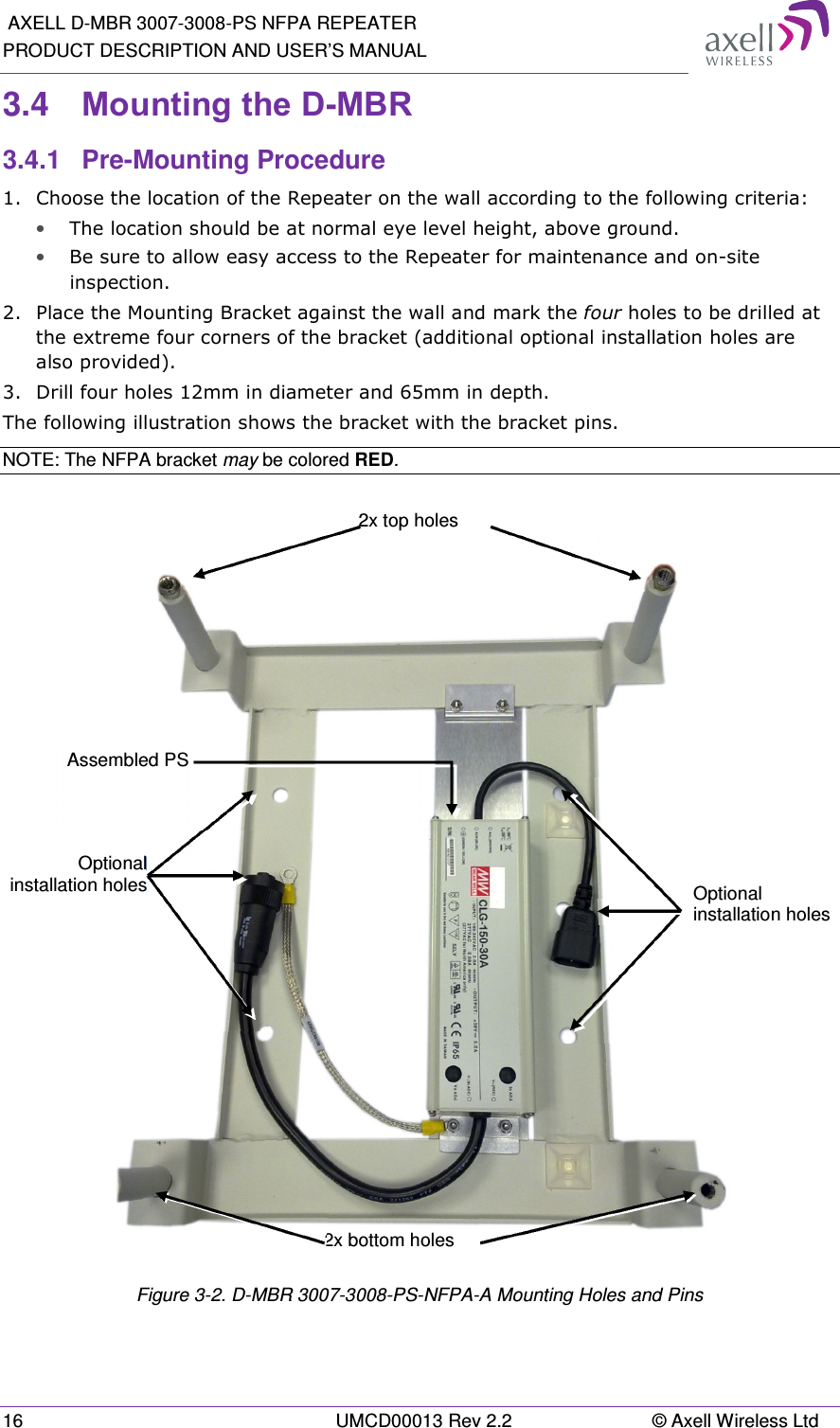
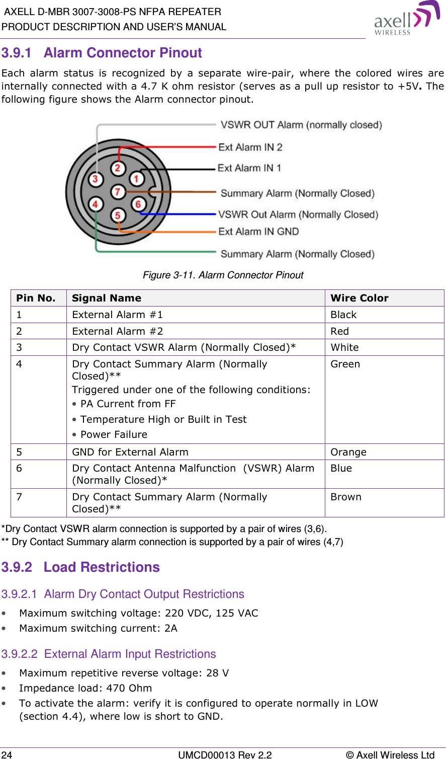
![Axell D-MBR 3007-3008-PS-NFPA PRODUCT DESCRIPTION AND USER’S MANUAL © Axell Wireless Ltd UMCD00013 Rev 2.2 9 2.2 Service Antenna Requirements The Service antenna type depends on whether the Repeater is installed indoors or outdoors. WARNINGS!!! • The installer is held accountable for implementing the rules required for deployment. • Good engineering practice must be used to avoid interference. • Output power should be reduced to solve any IMD interference issues. 2.2.1 Required Information The following antenna requirements, specifications and site considerations should be met: • Type of installation – indoor only • Service area type and size and characteristics • Height • Length and type of coaxial cable required for connecting the antenna to the Repeater and the attenuation. 2.2.2 Indoor Antenna Installations 2.2.2.1 Recommended Antennas The following describes the requirements for an omni-directional mobile used for indoor applications. Specifications: • One or a combination of the following antennas can be used: Ceiling Mount Patch antenna, Wall Mount Patch antenna, Corner Reflector. • Choose an antenna with high side lobe attenuation which enables maximum isolation. • Maximum antenna gain for indoor operation 2.2dBi. • Cable and jumper loss is at least 2dB. • [Gain Antenna – Cable loss] should not exceed 0.2 dB](https://usermanual.wiki/PBE-Europe-as-Axell-Wireless/DMBA30073008PS.User-manual/User-Guide-2452421-Page-19.png)
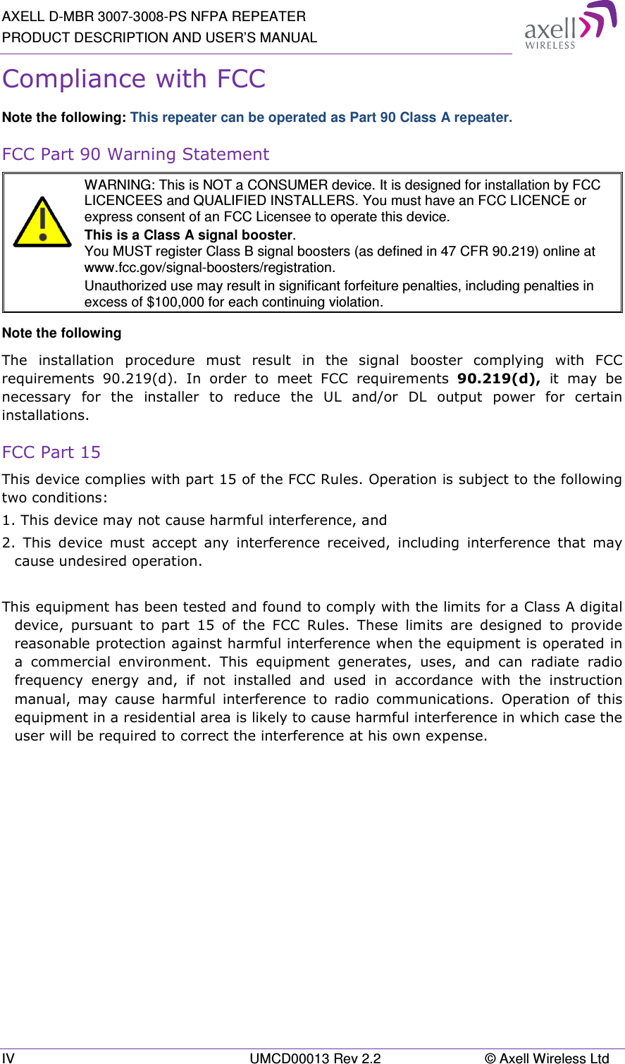
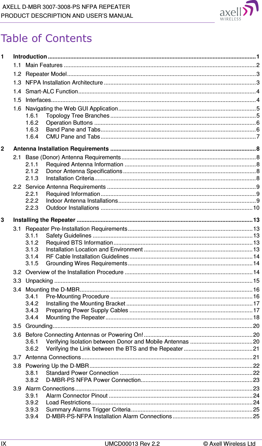
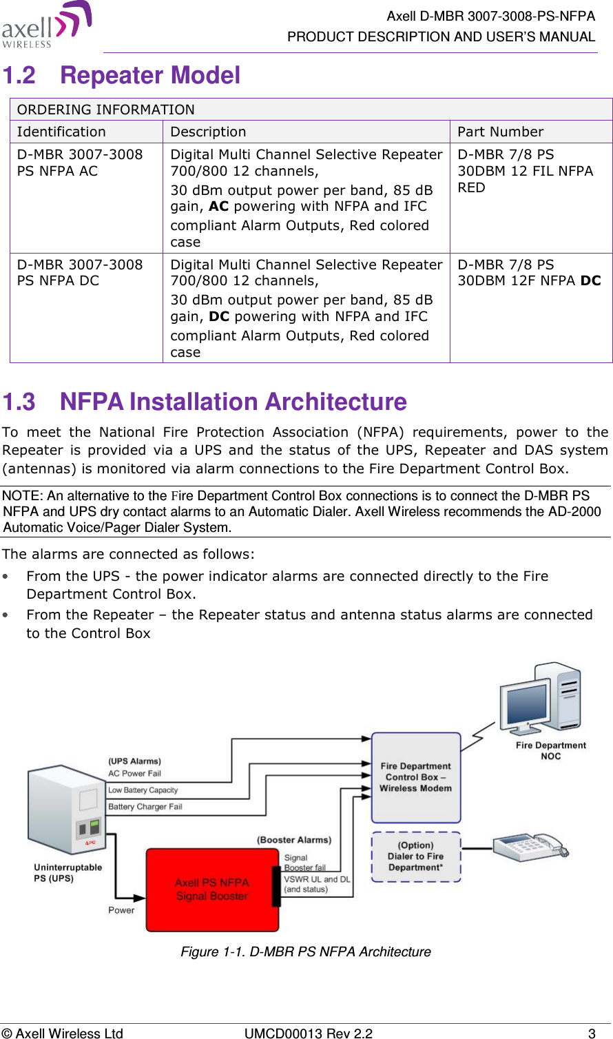
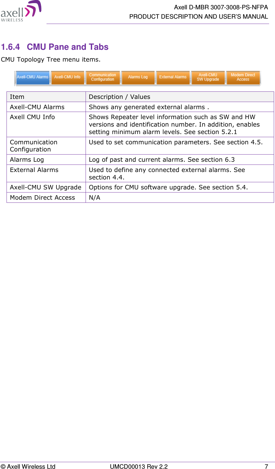
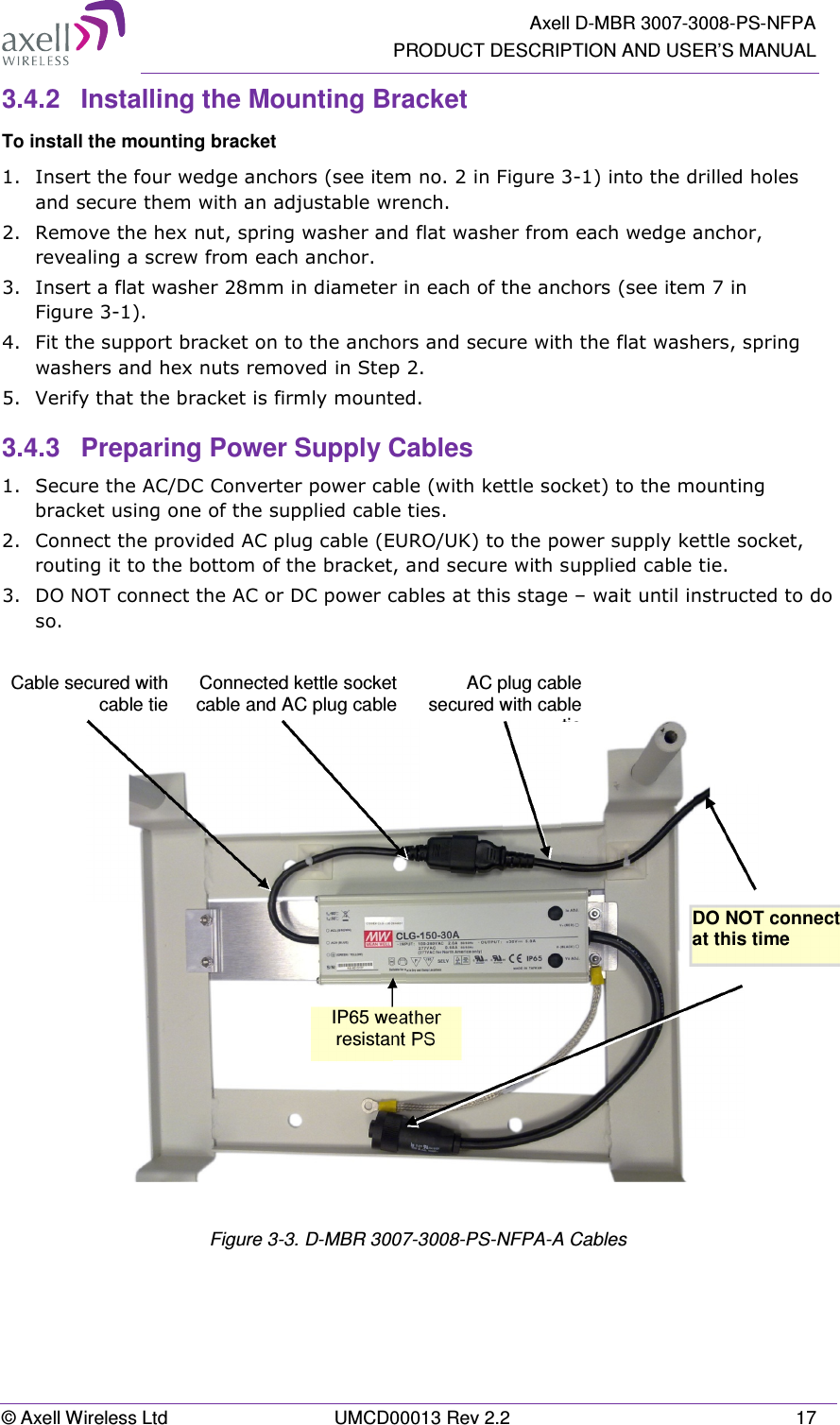
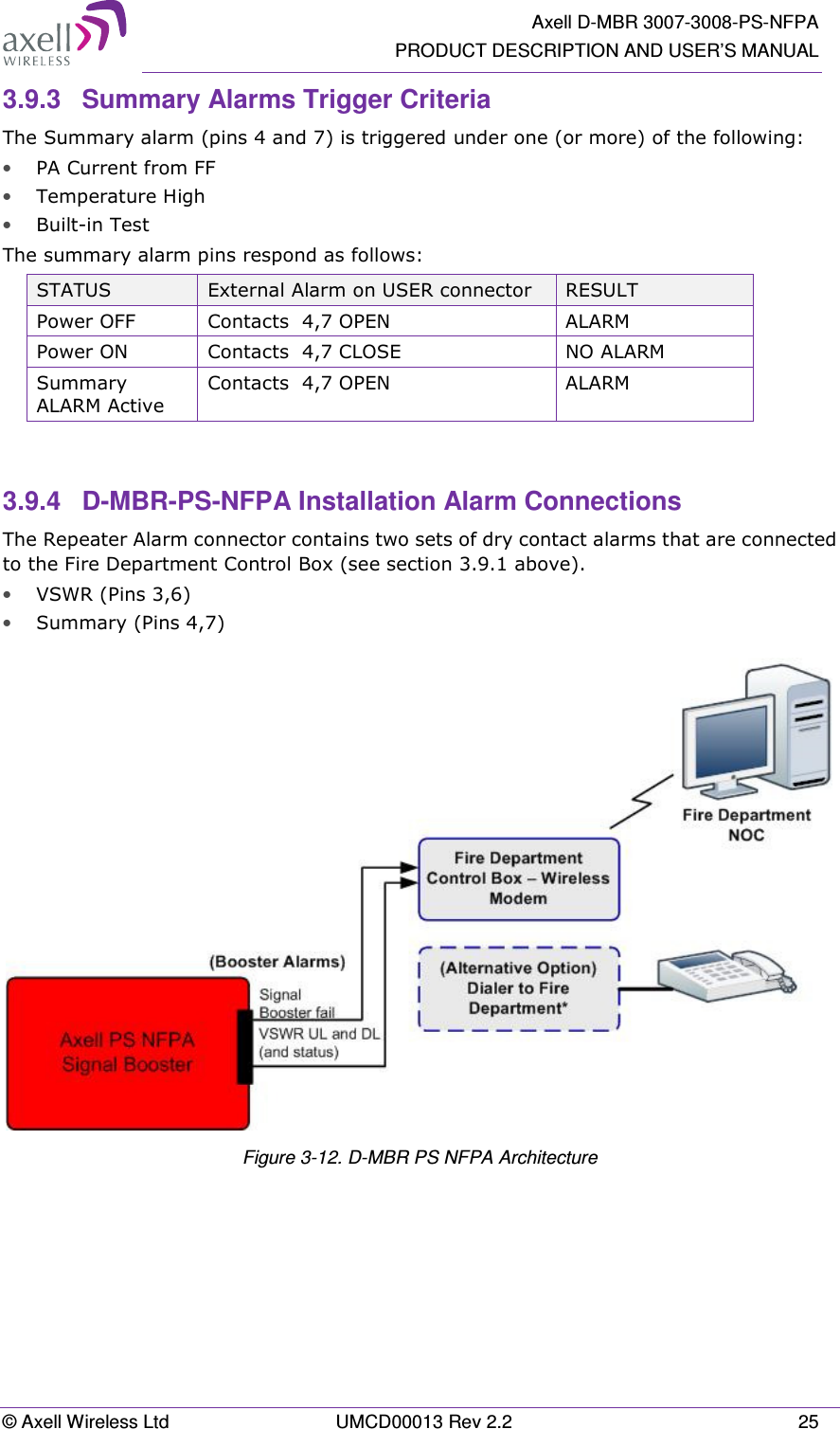
![AXELL D-MBR 3007-3008-PS NFPA REPEATER PRODUCT DESCRIPTION AND USER’S MANUAL 10 UMCD00013 Rev 2.2 © Axell Wireless Ltd 2.2.2.2 Installation Criteria Installation requirements: • An indoor antenna should be installed at a convenient location. It should be free of metallic obstruction. • Install the Service Antenna at the designated height and tune it roughly toward the Service coverage area. • Installation of this antenna must provide a minimum separation distance of 20cm from any personnel within the area. 2.2.3 Outdoor Installations For applications in which the Mobile antenna is installed outdoor, the antenna type is chosen according to the available infrastructure (single-pole or horizontal installation). In addition, isolation between the donor and service antennas must be taken into account when selecting the location of the antennas. 2.2.3.1 Recommended Antennas The antenna type depends on the installation: • For vertical Single Pole installations a high side lobe suppression antenna is required. • For horizontal installations either on two separate poles or on two sides of one building a high front to back ratio antenna is required. Specifications: • Maximum antenna gain for outdoor operation 8dBi. • Cable and jumper loss is at least 2dB. • [Gain Antenna – Cable loss] should not exceed 6dB Installation requirements: • Installation of this antenna must provide a minimum separation distance of 40 cm from any personnel within the area. NOTE: The Single Pole (Vertical) and Horizontal Installations are described in sections 2.2.3.2 and 2.2.3.3.](https://usermanual.wiki/PBE-Europe-as-Axell-Wireless/DMBA30073008PS.User-manual/User-Guide-2452421-Page-20.png)
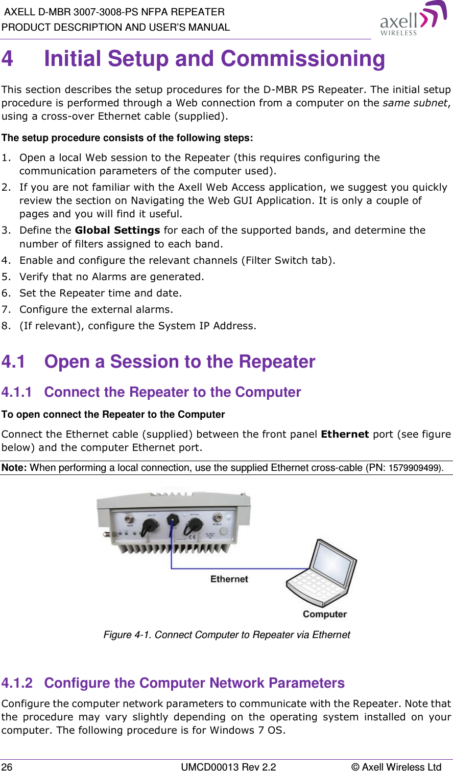
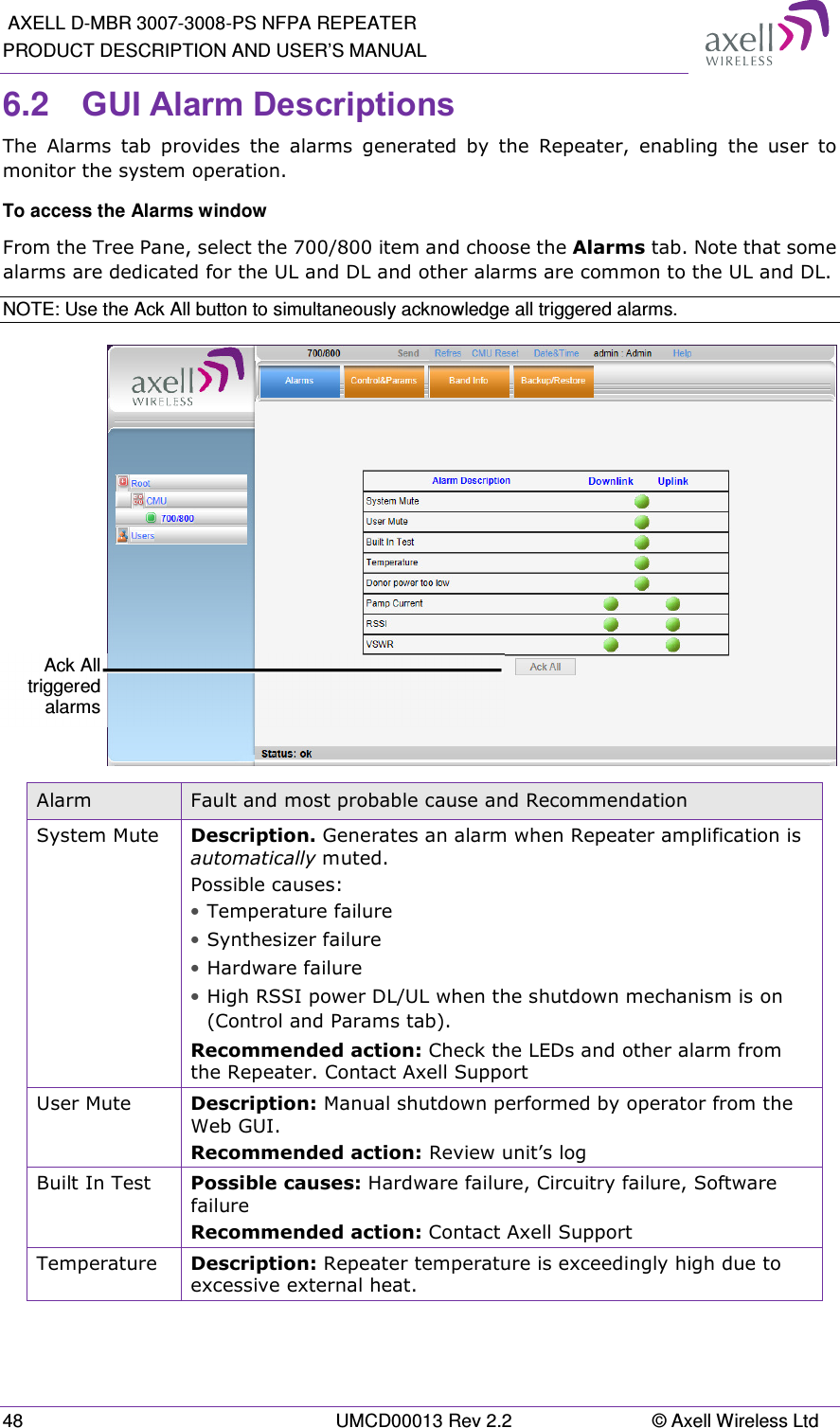
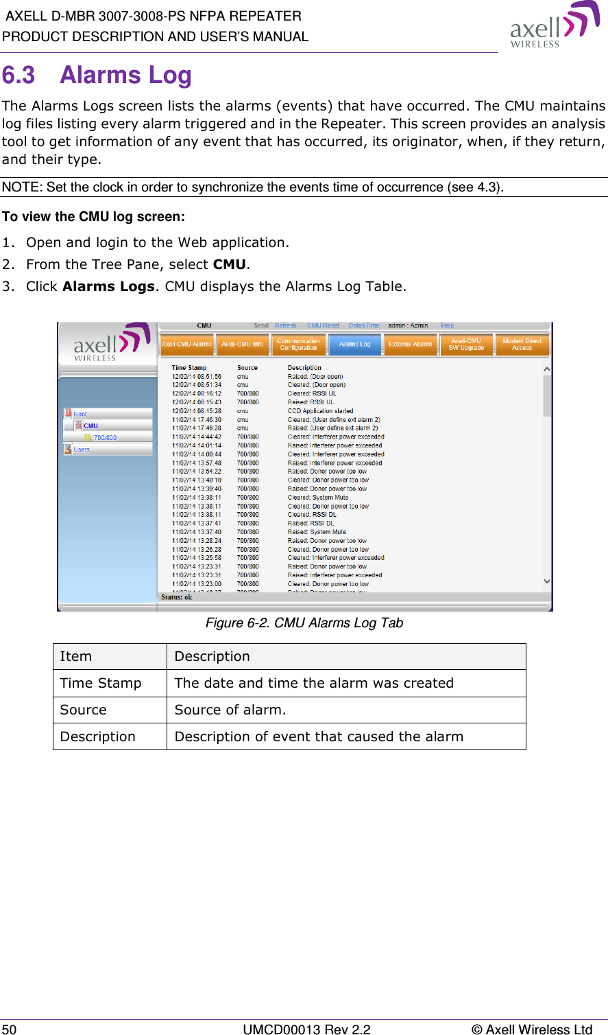
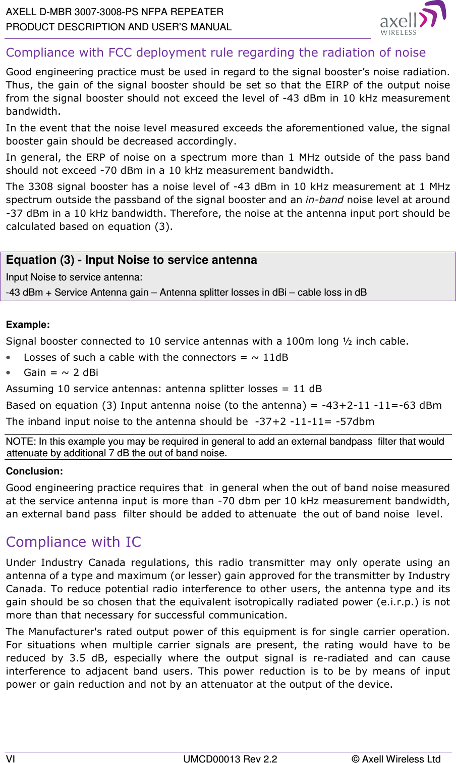
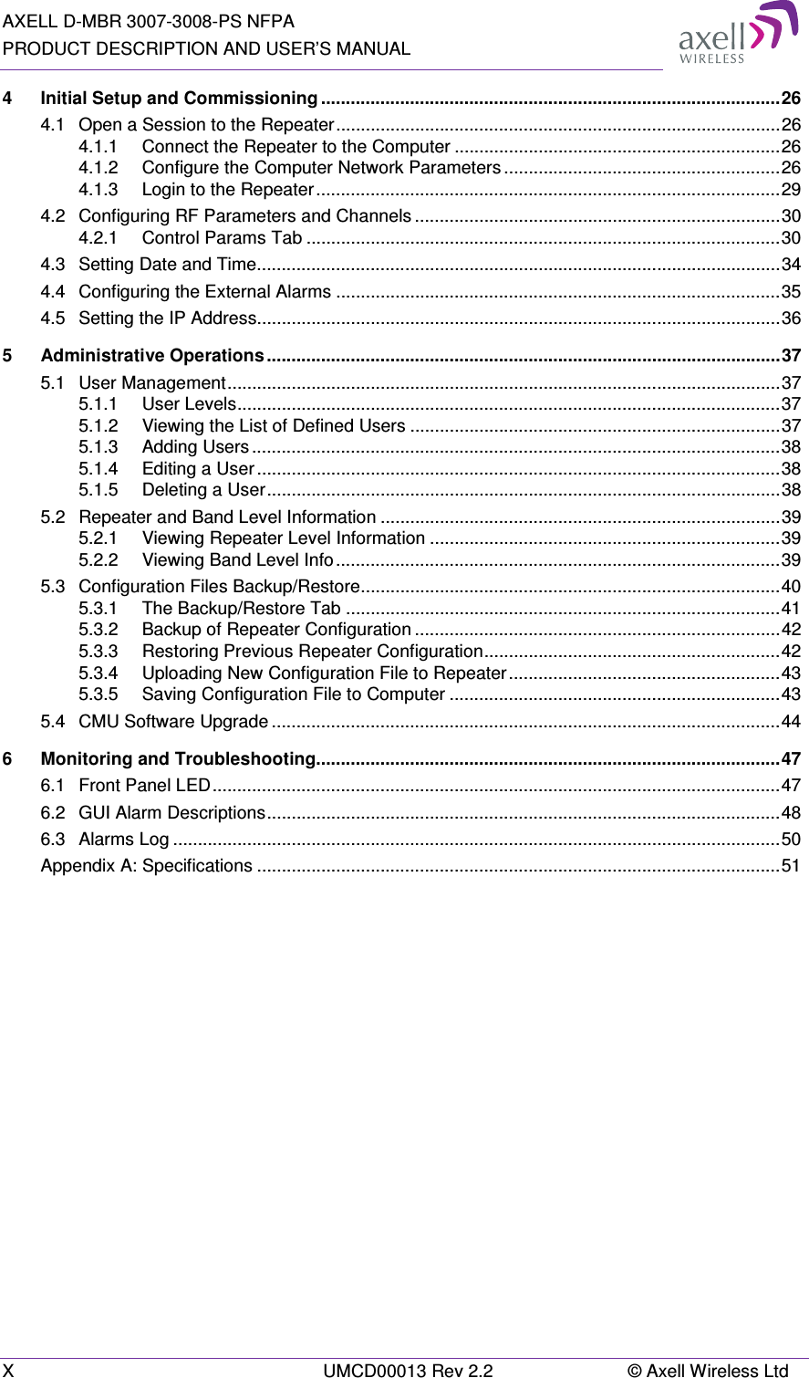
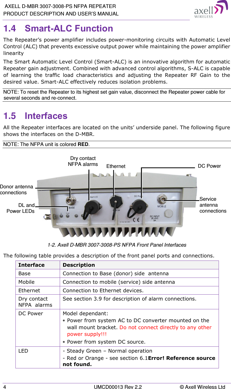
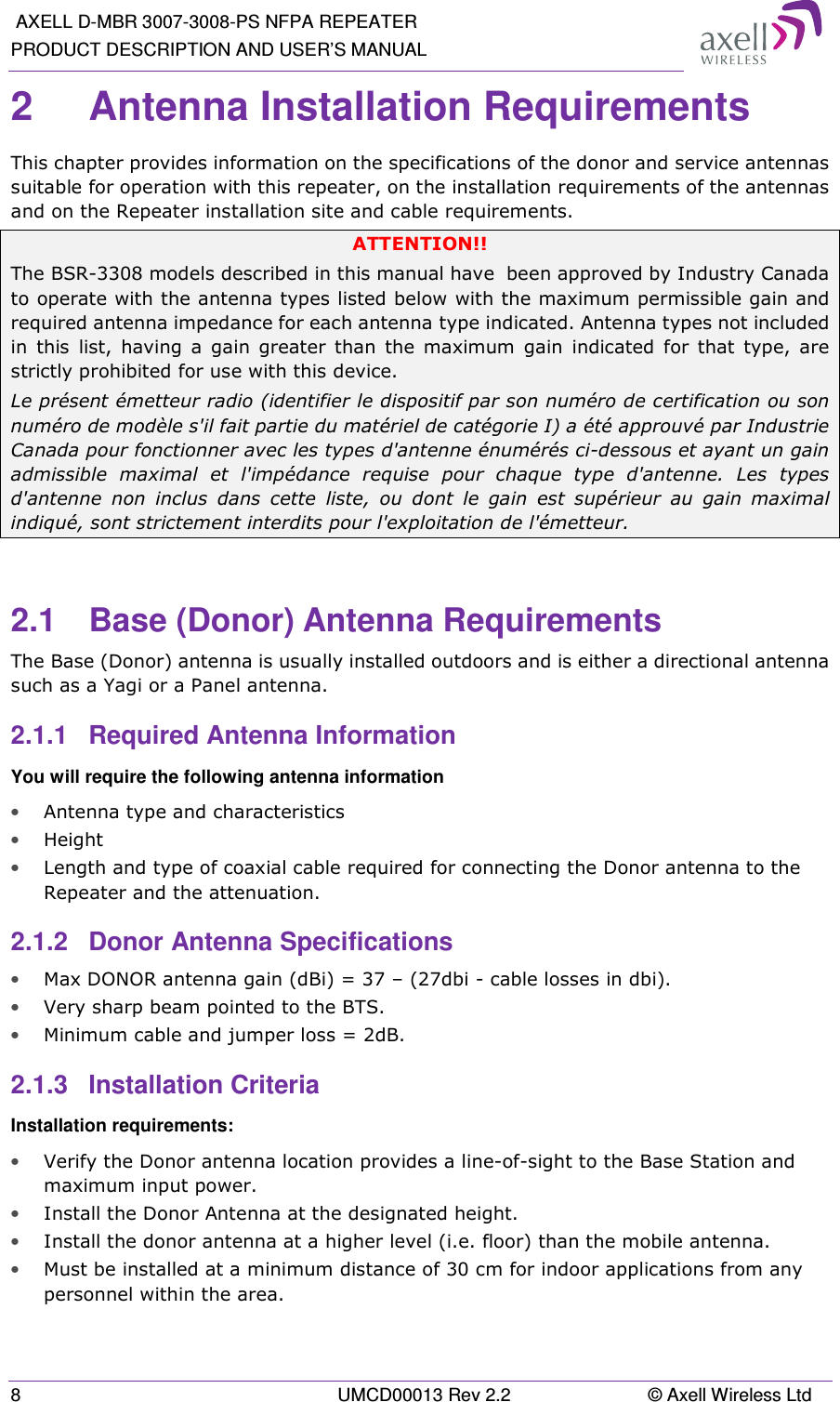
![Axell D-MBR 3007-3008-PS-NFPA PRODUCT DESCRIPTION AND USER’S MANUAL © Axell Wireless Ltd UMCD00013 Rev 2.2 49 Alarm Fault and most probable cause and Recommendation Recommended action: Check the Repeater case for external causes (sun, hot environment, air flow is blocked). Eliminate the reason for excessive heat. Donor Power Too Low Description: Signal from the Donor antenna (DL) is too low - relatively to the desired output signal configured by the user. Recommended action: • Check the Donor/Base connections and antenna position. • Check the signal level of the Donor/Base antenna. • If the Donor Power Too Low alarm is still raised, then you can raise, the value of the DL Output Threshold Delta[dBm] as needed. (PAmp) Current Description: Power Amplifier current is not within limits (too high or too low). If the Mute option is enabled, then this is not a fault since it indicates low Power Amplifier current caused by the mute. Recommended action: Check the LEDs status in the Repeater and Contact Axell service support. RSSI Description: Generates an alarm when a high donor input signal causes system gain reduction VSWR Description: This alarm is triggered when the return loss of the Downlink or Uplink antenna or cable connection exceed the allowed limit. This alarm provides an indication of the status of the cable/antenna connected to the antenna. If a cable/antenna is defective, the VSWR is decreased and the alarm is triggered. Recommended action: Check the cable.](https://usermanual.wiki/PBE-Europe-as-Axell-Wireless/DMBA30073008PS.User-manual/User-Guide-2452421-Page-59.png)