PBE Europe as Axell Wireless DMBA37073708PS Class A Booster User Manual
Axell Wireless Class A Booster Users Manual
Users Manual
Cobham Wireless – Coverage Date: 6-Set-15 www.cobham.com/wireless
Doc. No. 00060CDUM Rev. 1.0 Page | I
The most important thing we build is trust
D-MBR 3707 3708
PS NFPA Repeaters
The future of in-building coverage
User Manual – 00060CDUM Rev. 1.0
This manual is relevant for 700/800 MHz Digital Multi-Channel Class B RF Signal
Booster
D-MBR 3707-3708 PS NFPA Booster
D-MBR 3707-3708 AC feeder and battery charger

D-MBR 3707-3708 PS NFPA CLASS B SIGNAL BOOSTER
PRODUCT DESCRIPTION AND USER’S MANUAL
www.cobham.com/wireless Cobham Wireless – Coverage Date: 6-Set-15
Page | II Doc. No. 00060CDUM Rev. 1.0
Copyright © 2015 Axell Wireless Limited trading as Cobham Wireless
All rights reserved.
No part of this document may be copied, distributed, transmitted, transcribed, stored in a retrieval system, or
translated into any human or computer language without the prior written permission of Axell Wireless Limited
trading as Cobham Wireless.
The manufacturer has made every effort to ensure that the instructions contained in this document are
adequate and free of errors and omissions. The manufacturer will, if necessary, explain issues which may not be
covered by this document. The manufacturer's liability for any errors in the document is limited to the correction
of errors and the aforementioned advisory services.
This document has been prepared to be used by professional and properly trained personnel, and the customer
assumes full responsibility when using them. The manufacturer welcomes customer comments as part of the
process of continual development and improvement of the documentation in the best way possible from the
user's viewpoint. Please submit your comments to the nearest Cobham Wireless sales representative.
Contact Information
Headquarters Axell Wireless trading as Cobham Wireless
Aerial House, Asheridge Road
Chesham, Buckinghamshire
HP5 2QD, United Kingdom
Tel: +44 1494 777000
Fax: +44 1494 777002
Commercial inquiries cw.coverage@cobham.com
Website www.cobham.com/wireless
Support issues cw.support@cobham.com
Technical Support Line, English speaking +44 1494 777 747
About This Manual
This Product Manual provides the following information:
• Description of the Repeater unit
• Procedures for setup, configuration and checking the proper operation of the unit
• Maintenance and troubleshooting procedures
For whom it is intended
This Product Manual is intended for experienced technicians and engineers. It is assumed that the customers
installing, operating, and maintaining Cobham Wireless Repeaters are familiar with the basic functionality of
Repeaters.
Notice
Confidential - Authorized Customer Use
This document may be used in its complete form only and is solely for the use of Cobham Wireless employees
and authorized Cobham Wireless channels or customers. The material herein is proprietary to Cobham Wireless.
Any unauthorized reproduction, use or disclosure of any part thereof is strictly prohibited.
All trademarks and registered trademarks are the property of their respective owners.

D-MBR 3707-3708 PS NFPA CLASS B SIGNAL BOOSTER
PRODUCT DESCRIPTION AND USER’S MANUAL
Cobham Wireless – Coverage Date: 6-Set-15 www.cobham.com/wireless
Doc. No. 00060CDUM Rev. 1.0 Page | III
Disclaimer of Liability
Contents herein are current as of the date of publication. Cobham Wireless reserves the right to change the
contents without prior notice. The information furnished by Cobham Wireless in this document is believed to be
accurate and reliable. However, Cobham Wireless assumes no responsibility for its use. In no event shall
Cobham Wireless be liable for any damage resulting from loss of data, loss of use, or loss of profits and Cobham
Wireless further disclaims any and all liability for indirect, incidental, special, consequential or other similes
damages. This disclaimer of liability applies to all products, publications and services during and after the
warranty period.
Safety Instructions and Warnings
Throughout this manual, important safety warnings and admonishments are included to warn of possible
hazards to persons or equipment. A safety warning identifies a possible hazard and then describes what may
happen if the hazard is not avoided. The safety warnings – in the form of Dangers, Warnings and Cautions must
be followed at all times. These warnings are flagged by the use of a warning icon, usually the triangular alert
icon seen below. The exclamation point within the triangular alert icon is intended to warn the operator or
service personnel of operation and maintenance from factors relating to the product and its operating
environment, which could pose a safety hazard.
Guarantees
All antennas must be installed with lightning protection. Damage to power modules, as a result of lightning are
not covered by the warranty.
Switching on AC or DC power prior to the connection of antenna cables is regarded as faulty installation
procedure and therefore not covered by the Cobham Wireless warranty.
Repeater enclosures should be closed using the two screws. The screws must be fully tightened. Failure to do so
may affect the IP65 compliancy and therefore any warranty.
Exclusive Remedies
The remedies provided herein are the Buyer’s sole and exclusive remedies. Cobham Wireless shall not be viable
for any direct, incidental, or consequential damages, whether based on contract, tort, or any legal theory.
D-MBR 3707-3708 PS NFPA CLASS B SIGNAL BOOSTER
PRODUCT DESCRIPTION AND USER’S MANUAL
www.cobham.com/wireless Cobham Wireless – Coverage Date: 6-Set-15
Page | IV Doc. No. 00060CDUM Rev. 1.0
General Safety Warnings Concerning Use of System
Always observe standard safety precautions during installation, operation and maintenance of this
product.
Caution labels!
Throughout this manual, there are "Caution" warnings. "Caution" calls attention to
a procedure or practice, which, if ignored, may result in injury or damage to the
system, system component or even the user. Do not perform any procedure
preceded by a "Caution" until the described conditions are fully understood and
met.
Danger: Electrical Shock
This equipment can either be installed indoors or outdoors. When installed
outdoors - wet conditions increase the potential for receiving an electric shock
when installing or using electrically powered equipment. To prevent electrical shock
when installing or modifying the system power wiring, disconnect the wiring at the
power source before working with un insulated wires or terminals.
Caution: Safety to
personnel
Before installing or replacing any of the equipment, the entire manual should be
read and understood.
The user needs to supply the appropriate AC or DC power to the booster. Incorrect
power settings can damage the Booster and may cause injury to the user.
Please be aware that the equipment may, during certain conditions become very
warm and can cause minor injuries if handled without any protection, such as
gloves.
Caution: Safety to
equipment
When installing, replacing or using this product, observe all safety precautions
during handling and operation. Failure to comply with the following general safety
precautions and with specific precautions described elsewhere in this manual
violates the safety standards of the design, manufacture, and intended use of this
product.
Axell Wireless assumes no liability for the customer's failure to comply with these
precautions. This entire manual should be read and understood before operating or
maintaining the booster.
Warning: Restricted
Access Location
Access to the unit installation location is restricted to SERVICE PERSONNEL and to
USERS who have been instructed on the restrictions and the required precautions
to be taken.
Compliance with FCC
WARNING!!! This is NOT a CONSUMER device. This device is designed for installation by FCC
LICENCEES and QUALIFIED INSTALLERS. You must have an FCC LICENCE or express consent of an
FCC Licensee to operate this device.
Depending on the configuration, this device can operate as either a Class A or a Class B signal booster.
You MUST register Class B signal boosters (as defined in 47 CFR 90.219) online at www.fcc.gov/signal-
boosters/registration.
Unauthorized use may result in significant forfeiture penalties, including penalties in excess of $100,000
for each continuing violation.
The installation procedure must result in the signal booster complying with FCC requirements
90.219(d). In order to meet FCC requirements 90.219(d), it may be necessary for the installer to
reduce the UL and/or DL output power for certain installations.

D-MBR 3707-3708 PS NFPA CLASS B SIGNAL BOOSTER
PRODUCT DESCRIPTION AND USER’S MANUAL
Cobham Wireless – Coverage Date: 6-Set-15 www.cobham.com/wireless
Doc. No. 00060CDUM Rev. 1.0 Page | V
FCC Part 15
This device complies with part 15 of the FCC Rules. Operation is subject to the following two conditions:
1. This device may not cause harmful interference, and
2. This device must accept any interference received, including interference that may cause undesired operation.
If not installed and used in accordance with the instructions, this equipment generates, uses and can radiate
radio frequency energy. However, there is no guarantee that interference will not occur in a particular
installation. If this equipment does cause harmful interference to RF reception, which can be determined by
turning the equipment off and on, the user is encouraged to try to correct the interference by one or more of
the following measures:
Reorient or relocate the Donor antenna.
Increase the separation between the equipment and receiver.
Connect the equipment into an outlet on a circuit different from that to which the receiver is connected.
Unauthorized Changes to Equipment
Changes or Modifications not expressly approved by the manufacturer responsible for compliance could void the
user’s authority to operate the equipment
FCC RF Exposure Limits
This unit complies with FCC RF exposure limits for an uncontrolled environment. This equipment must be
installed and operated with a minimum distance of 28cm between the radiator and any person’s body.
Antenna Installation
Installation of an antenna must comply with the FCC RF exposure requirements. The antenna used for this
transmitter must be mounted on outdoor or indoor permanent structures. The maximum antenna gain for indoor
operation is 2.2 dBi and for the external antenna is 7dBi. Cable loss of at least 2dB is taken into account for all
cases.Antennas having a gain greater than these are strictly prohibited for use with this device. In indoor
applications the antenna must be installed at a minimum separation distance of 28cm from all nearby persons.

D-MBR 3707-3708 PS NFPA CLASS B SIGNAL BOOSTER
PRODUCT DESCRIPTION AND USER’S MANUAL
www.cobham.com/wireless Cobham Wireless – Coverage Date: 6-Set-15
Page | VI Doc. No. 00060CDUM Rev. 1.0
Compliance with IC
Under Industry Canada regulations, this radio transmitter may only operate using an antenna of a type and
maximum (or lesser) gain approved for the transmitter by Industry Canada. To reduce potential radio
interference to other users, the antenna type and its gain should be so chosen that the equivalent isotropically
radiated power (e.i.r.p.) is not more than that necessary for successful communication.
The Manufacturer's rated output power of this equipment is for single carrier operation. For situations when
multiple carrier signals are present, the rating would have to be reduced by 3.5 dB, especially where the output
signal is re-radiated and can cause interference to adjacent band users. This power reduction is to be by means
of input power or gain reduction and not by an attenuator at the output of the device.
This equipment complies with IC RSS-102 radiation exposure limits set forth for an uncontrolled environment.
This equipment should be installed and operated with minimum distance 28 cm between the antenna and your
body,
Conformément à la réglementation d'Industrie Canada, le présent émetteur radio peut fonctionner avec une
antenne d'un type et d'un gain maximal (ou inférieur) approuvé pour l'émetteur par Industrie Canada. Dans le
but de réduire les risques de brouillage radioélectrique à l'intention des autres utilisateurs, il faut choisir le type
d'antenne et son gain de sorte que la puissance isotrope rayonnée équivalente (p.i.r.e.) ne dépasse pas
l'intensité nécessaire à l'établissement d'une communication satisfaisante.
La puissance de sortie nominale indiquée par le fabricant pour cet appareil concerne son fonctionnement avec
porteuse unique. Pour des appareils avec porteuses multiples, on doit réduire la valeur nominale de 3.5 dB,
surtout si le signal de sortie est retransmis et qu'il peut causer du brouillage aux utilisateurs de bandes
adjacentes. Une telle réduction doit porter sur la puissance d'entrée ou sur le gain, et ne doit pas se faire au
moyen d'un atténuateur raccordé à la sortie du dispositif.
Cet appareil est conforme aux limitations de la norme IC RSS-102 concernant l’exposition aux radiations dans un
environnement non contrôlé. Cet appareil doit être installé et utilisé avec une distance minimale de 28 cm entre
l’antenne et le corps de l’utilisateur.

Cobham Wireless – Coverage Date: 6-Set-15 www.cobham.com/wireless
Doc. No. 00060CDUM Rev. 1.0 Page | VII
Table of Contents
1 INTRODUCTION ............................................................................................................ 1
1.1 Main Features......................................................................................................... 1
1.2 Booster Ordering Information ................................................................................. 2
1.3 Architecture ........................................................................................................... 2
1.4 Smart-ALC Function ............................................................................................... 3
1.5 Power Feeder and Battery Charger ......................................................................... 3
1.6 Booster Interfaces .................................................................................................. 4
1.7 Functional Description ........................................................................................... 5
2 ANTENNA REQUIREMENTS........................................................................................... 6
2.1 Donor Antenna ....................................................................................................... 6
2.1.1 Required Antenna Information ............................................................................6
2.1.2 Donor Antenna specifications .............................................................................6
2.1.3 Installation Criteria .............................................................................................6
2.2 Service Antenna ..................................................................................................... 7
2.2.1 Required Information .........................................................................................7
2.2.2 Indoor Installations .............................................................................................7
2.2.3 Outdoor Installations ..........................................................................................8
3 INSTALLING THE SIGNAL BOOSTER ........................................................................... 10
3.1 Overview of the Physical Installation Procedure .................................................... 10
3.2 Pre-installation Requirements ............................................................................... 11
3.2.1 Required BTS Information ................................................................................ 11
3.2.2 Installation Location Criteria and Environment ................................................... 11
3.3 Booster Unpacking and Package Contents ........................................................... 12
3.4 Mounting the System ............................................................................................ 13
3.4.1 Bracket Assembly ............................................................................................ 13
3.4.2 Wall Marking and Drilling .................................................................................. 15
3.4.3 Mount the Unit ................................................................................................. 18
3.4.4 Recommended Additional Fixing ....................................................................... 19
3.5 Grounding ............................................................................................................ 21
3.5.1 Grounding Wire Requirements .......................................................................... 21
3.5.2 Grounding Units .............................................................................................. 21
3.6 Antenna Connections and Guidelines ................................................................... 21
3.6.1 Verifying Isolation between Donor and Service Antennas ................................... 22
3.6.2 Verifying the Link between the BTS and the Signal Booster ................................ 22
3.6.3 RF Cable Installation Guidelines ....................................................................... 23
3.6.4 Connecting Antennas ....................................................................................... 23
3.7 Connecting Power and Power-Up ......................................................................... 24
3.8 Booster Dry-Contact Alarm Connections .............................................................. 25
3.8.1 Load Restrictions ............................................................................................. 25
3.8.2 Booster Alarm Connector Pinout ....................................................................... 26
4 BATTERY CHARGER DESCRIPTION AND INSTALLATION ............................................ 27
4.1 Charger Ordering Information ............................................................................... 27
4.2 Charger Architecture ............................................................................................ 28
4.3 Charger Interfaces ................................................................................................ 29
4.4 Charger Installation Procedure ............................................................................. 30
4.4.1 Charger Installation Location ............................................................................ 30

D-MBR 3707-3708 PS NFPA CLASS B SIGNAL BOOSTER
PRODUCT DESCRIPTION AND USER’S MANUAL
www.cobham.com/wireless Cobham Wireless – Coverage Date: 6-Set-15
Page | VIII Doc. No. 00060CDUM Rev. 1.0
4.4.2 Charger Unpacking and Package Contents ....................................................... 31
4.4.3 Charger Wallmount Procedure .......................................................................... 31
4.4.4 Charger Grounding .......................................................................................... 32
4.4.5 Charger Power Connections ............................................................................. 32
4.4.6 Connection to External Battery ......................................................................... 33
4.4.7 Charger Alarm Connections ............................................................................. 33
5 SETUP AND COMMISSIONING ..................................................................................... 35
5.1 Overview of the Commissioning Procedure ........................................................... 35
5.2 Opening a Session to the Booster and Navigating the GUI ..................................... 36
5.2.1 Open a First Time Local Web Session to the Booster ......................................... 36
5.2.2 Navigating the Web GUI Application ................................................................. 38
5.3 RF Parameters and Channel Configuration ............................................................ 41
5.4 Date and Time Settings ......................................................................................... 45
5.5 External Alarms Configuration .............................................................................. 46
5.6 IP Address and SNMP Notifications ....................................................................... 47
5.6.1 Configuring the IP Address ............................................................................... 48
5.6.2 SNMP Trap Configuration ................................................................................ 49
5.7 Changing Password .............................................................................................. 50
6 ADMINISTRATIVE OPERATIONS .................................................................................. 51
6.1 User Management ................................................................................................. 51
6.1.1 User Levels ..................................................................................................... 51
6.1.2 Viewing the List of Defined Users...................................................................... 51
6.1.3 Adding Users ................................................................................................... 52
6.1.4 Editing a User .................................................................................................. 53
6.1.5 Deleting a User ................................................................................................ 53
6.2 Viewing General Information ................................................................................. 53
6.2.1 Viewing Booster Level Information .................................................................... 53
6.2.2 Viewing Band Level Info ................................................................................... 54
6.3 Band-Level Configuration Backup/Restore ............................................................ 55
6.3.1 The Backup/Restore Tab .................................................................................. 55
6.3.2 Backup Band Configuration .............................................................................. 56
6.3.3 Restoring Band Configuration ........................................................................... 56
6.3.4 Uploading Band Configuration File .................................................................... 57
6.3.5 Saving Configuration File to Computer .............................................................. 57
6.4 CMU Software Upgrade ......................................................................................... 58
7 MONITORING AND TROUBLESHOOTING ..................................................................... 59
7.1 LED Troubleshooting ............................................................................................ 59
7.2 Booster Level Alarms Log ..................................................................................... 60
7.3 CMU Alarms .......................................................................................................... 61
7.4 Band-Level Alarms and Troubleshooting ............................................................... 62
7.5 Modifying Alarm Severities .................................................................................... 64
Appendix A – Booster and Charger Specifications ........................................................ 65

D-MBR 3707-3708 PS NFPA Class B Signal Booster
PRODUCT DESCRIPTION AND USER’S MANUAL
Cobham Wireless – Coverage Date: 6-Set-15 www.cobham.com/wireless
Doc. No. 00060CDUM Rev. 1.0 Page | 1
1 INTRODUCTION
This manual describes the installation and setup procedures for D-MBR Public Safety Signal Boosters
providing SMR 700 and 800MHz band at 37dBm output power per band.
D-MBR 3707-3708 PS NFPA (Digital Multi Band Booster for Public Safety) is a Class B Digital Multi-
Channel Signal Booster (DCSB). It features an array of up to 12 DSP based, software-controlled,
variable bandwidth filters, that are user-programmable across the 700 and 800 MHz bands.
D-MBR 3707-3708 PS NFPA supports all public safety technologies. For each filter, the user can
specify the start and stop frequencies to reduce the installation time of the signal booster and enable
a very wide range of filters selection.
Every parameter of D-MBR 3707-3708 PS NFPA, including filter tuning and selection, can be
controlled via web based management. The patented Cobham Wireless’ digital RF filter enables
simple initial setup for any channel plan and if necessary, allows some basic reconfiguration due to
re-banding.
The SALC -Smart ALC algorithm will reduce the gain to protect the signal booster from oscillation.
When the gain cannot be reduced anymore a shut-down mechanism will be triggered.
The signal booster protects against degradation of the system’s sensitivity and coverage. This is
implemented by the inbuilt AGC per-channel (filter) feature, which permits equalization of the
channel levels for uniform coverage.
This product meets the rigid requirements as defined by the NFPA and International Fire Code
developmental organizations. The amplifier is painted a Fire Life Safety Red, meets NEMA4
compliance for hose down, and provides all Alarming outputs as defined by NFPA 2010, Chapter 24
including system and antenna failures. The signal booster is a DC fed unit.
An external battery charger unit is available as well. The charger is connected to the AC and includes
a circuit to charge external batteries with all the dry contact alarms as defined in the NFPA standard:
AC failure, Charger failure and Low battery.
1.1 Main Features
• Class B- signal booster for SMR and public safety networks
• Supports APCO 25 phase 1 and 2 for public safety networks
• NFPA 72-2010, Chapter 24 and IFC 510.1 Compliant
• Support of 700MHz D block for LTE network
• Patented DSP filtering™ technology:
• Supports up to 12 independent filters per band
• User programmable bandwidth / frequency
• NEMA4 enclosure
• SALC-Smart ALC mechanism to protect the digital signal booster from oscillation and shutdown
the signal booster when required
• Web based management, SNMP traps
D-MBR 3707-3708 PS NFPA CLASS B SIGNAL BOOSTER
PRODUCT DESCRIPTION AND USER’S MANUAL
www.cobham.com/wireless Cobham Wireless – Coverage Date: 6-Set-15
Page | 2 Doc. No. 00060CDUM Rev. 1.0
1.2 Booster Ordering Information
NOTE: Charger ordering information is provided in section 4.1.
IDENTIFICATION DESCRIPTION PART NUMBER
D-MBR 3707-3708 PS
with NFPA and Red
painted case
Digital Multi Channel Selective Signal Booster
Class B 700/800 MHz 12
filters, 37dBm
composite per band, 95dB gain, DC powering
with NFPA and IFC compliant Alarm Outputs
and red painted case.
D-MBR 3707-3708-PS-
NFPA-DC-CLASS-B
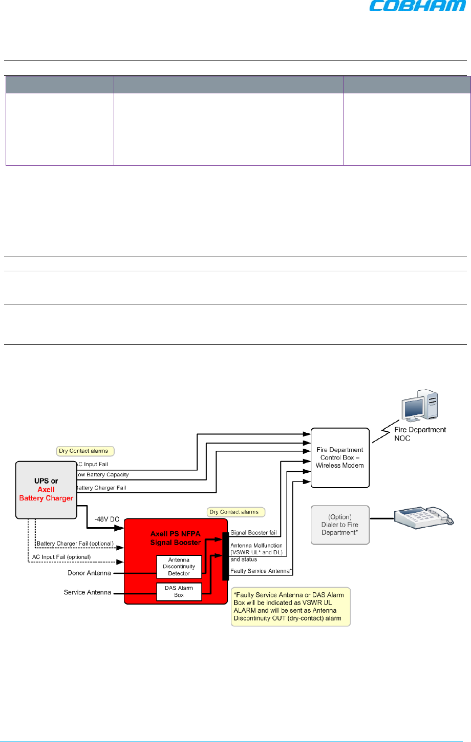
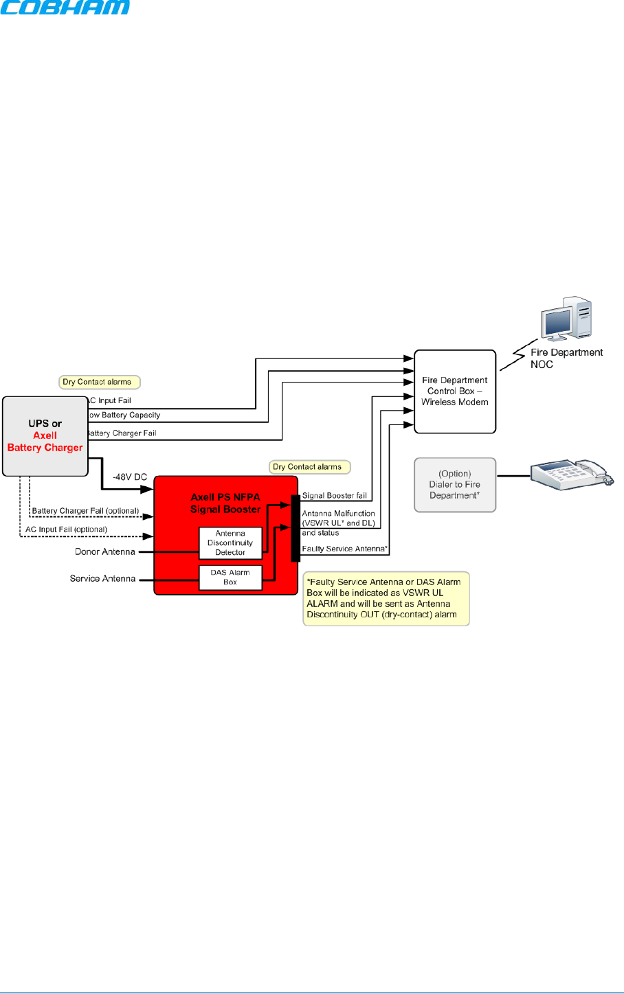
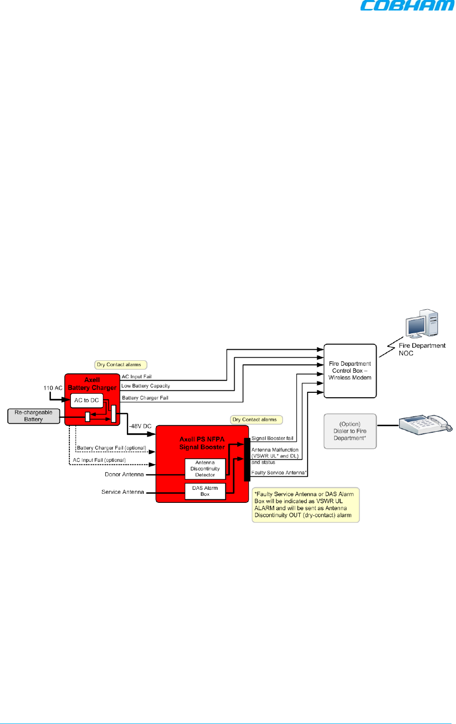
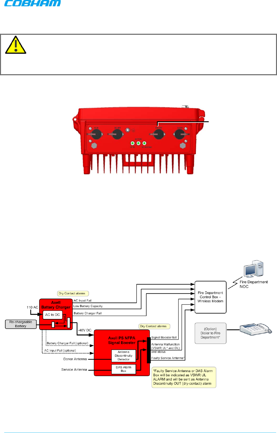
1.3 Architecture
To meet the National Fire Protection Association (NFPA) requirements, power to the Signal booster is
provided via an uninterrupted power source. This can either be a UPS or (if a UPS is not available),
an AC Feeder and Battery Charger (purchased separately).
NOTE: The Power Feeder Battery Charger is described in Chapter - 4).
Alarm connections to the Fire Department Control Box are used to monitor the status of the
uninterrupted power source, Signal Booster and DAS system (antennas).
NOTE: As an alternative to the Fire Department Control Box connections, the D-MBR PS NFPA and
UPS or Charger dry contact alarms can be connected to an Automatic Dialer. The AD-2000
Automatic Voice/Pager Dialer System is recommended.
If the AC power to the UPS fails, the required power is provided by the battery and the AC Power Fail
alarm is activated.
Figure 1-1. D-MBR PS NFPA Architecture
D-MBR 3707-3708 PS NFPA CLASS B SIGNAL BOOSTER
PRODUCT DESCRIPTION AND USER’S MANUAL
Cobham Wireless – Coverage Date: 6-Set-15 www.cobham.com/wireless
Doc. No. 00060CDUM Rev. 1.0 Page | 3
1.4 Smart-ALC Function
The Signal Booster’s power amplifier includes power-monitoring circuits with Automatic Level Control
(ALC) that prevents excessive output power while maintaining the power amplifier linearity
The Smart Automatic Level Control (Smart-ALC) is an innovative algorithm for automatic Signal
Booster gain adjustment. Combined with advanced control algorithms, SALC is capable of learning
the traffic load characteristics and adjusting the Signal Booster RF Gain to the desired value.
Note: To reset the Signal Booster to its highest set gain value, disconnect the Signal Booster power
cable for several seconds and re-connect.
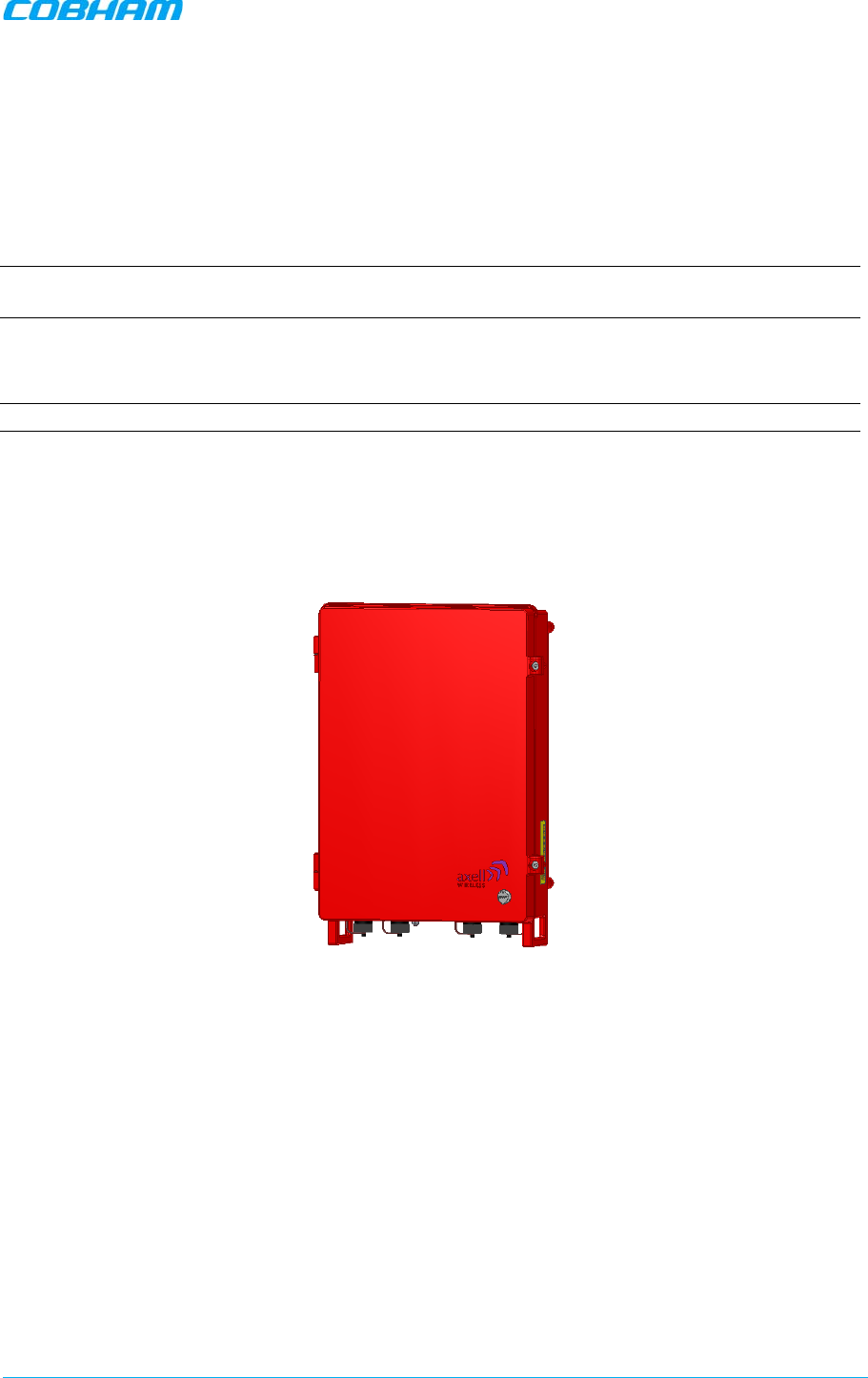
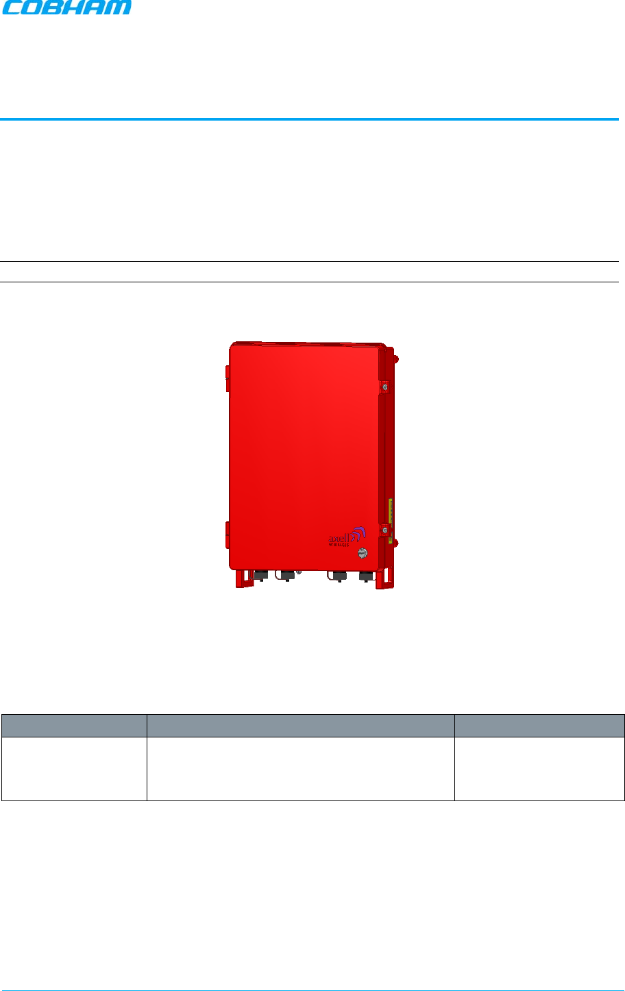
1.5 Power Feeder and Battery Charger
NOTE: The Power Feeder and Battery Charger is described in Chapter - 4).
For installations where UPS is not available, the AC Feeder and Battery Charger unit can be
purchased (see section 4.1 for ordering information).
The charger is connected directly to the AC inlet and includes a circuit to charge external batteries
(meeting the specifications described in section 4.4.6. The charger also includes the following dry
contact alarms (as defined in the NFPA standard): AC failure, Charger failure and Low battery.
Figure 1-2. D-MBR Charger
D-MBR 3707-3708 PS NFPA CLASS B SIGNAL BOOSTER
PRODUCT DESCRIPTION AND USER’S MANUAL
www.cobham.com/wireless Cobham Wireless – Coverage Date: 6-Set-15
Page | 4 Doc. No. 00060CDUM Rev. 1.0
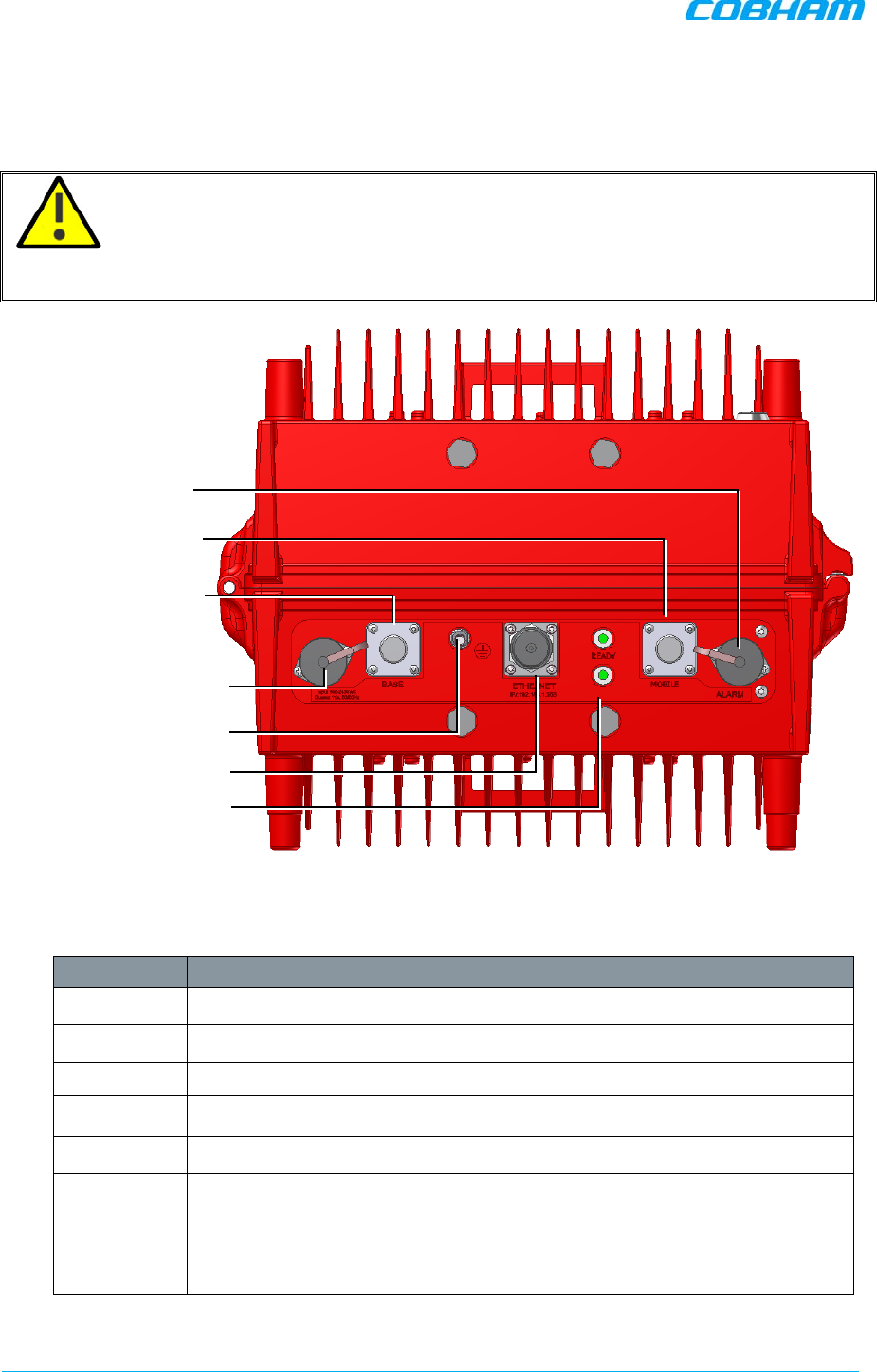
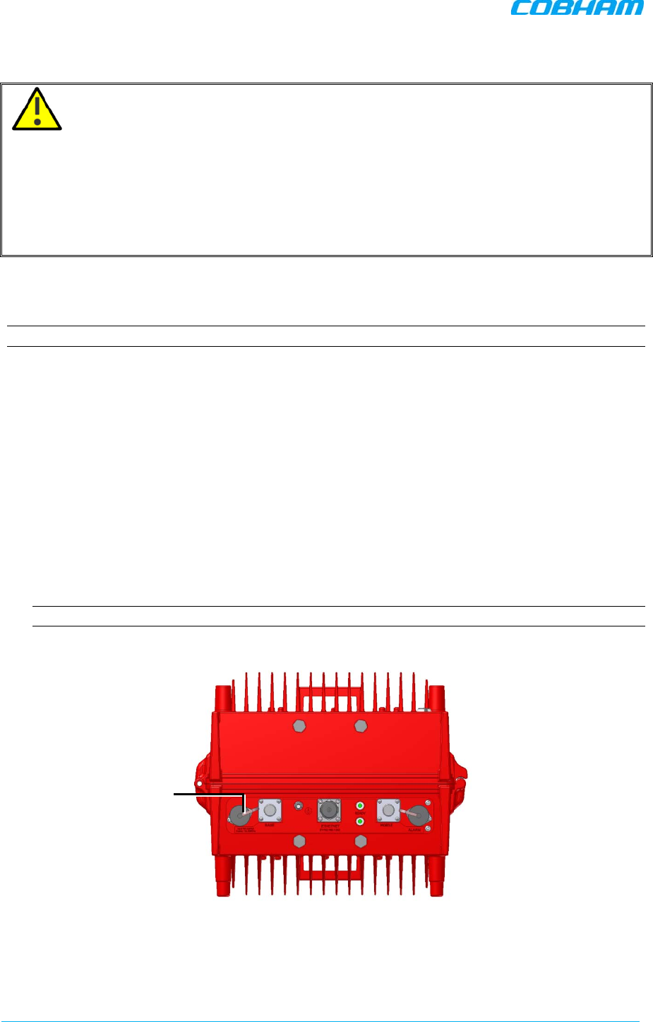
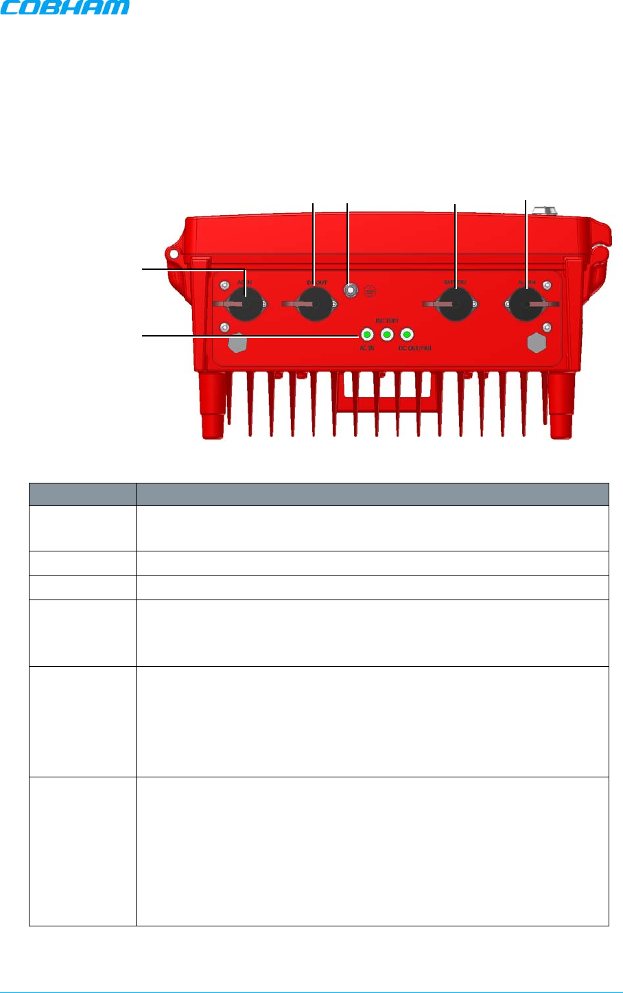
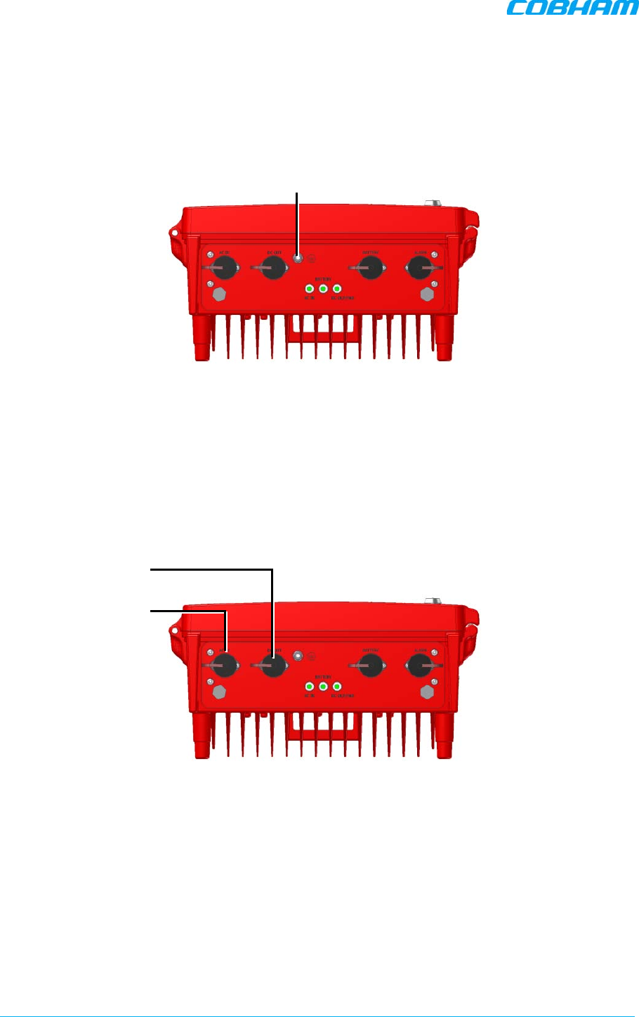
1.6 Booster Interfaces
All booster interfaces are located on the underside as shown below.
WARNING! The signal booster must always be installed vertically and top-down – with
the connectors on the underside for protection (see 3.4.4). Horizontal installation on a bench for long
time may cause damage to the signal booster due to over-heating.
Figure 1-3. D-MBR Front Panel
Interface Description
BASE Donor antenna connections. See section 2.1.
MOBILE Service antenna connections. See section 2.2.
48 VDC Connection to 48VDC (either from UPS or from the Charger).
ALARMS Two External (input) and two Output (relay) alarms. See section 3.8.
GND LUG Ground connection. See section 3.5.
LED’S Two status LEDs: 700 MHz and 800 MHz bands
Upper LED: UL status (for both bands.
Lower LED: DL status for both bands
Status: Green (OK), Orange (Warning), Red (Fail).
Donor antenna
connection
Service antenna
connection
48V DC power
GND LUG
Dry contact alarms
Ethernet port
Signal Status LEDs
D-MBR 3707-3708 PS NFPA CLASS B SIGNAL BOOSTER
PRODUCT DESCRIPTION AND USER’S MANUAL
Cobham Wireless – Coverage Date: 6-Set-15 www.cobham.com/wireless
Doc. No. 00060CDUM Rev. 1.0 Page | 5
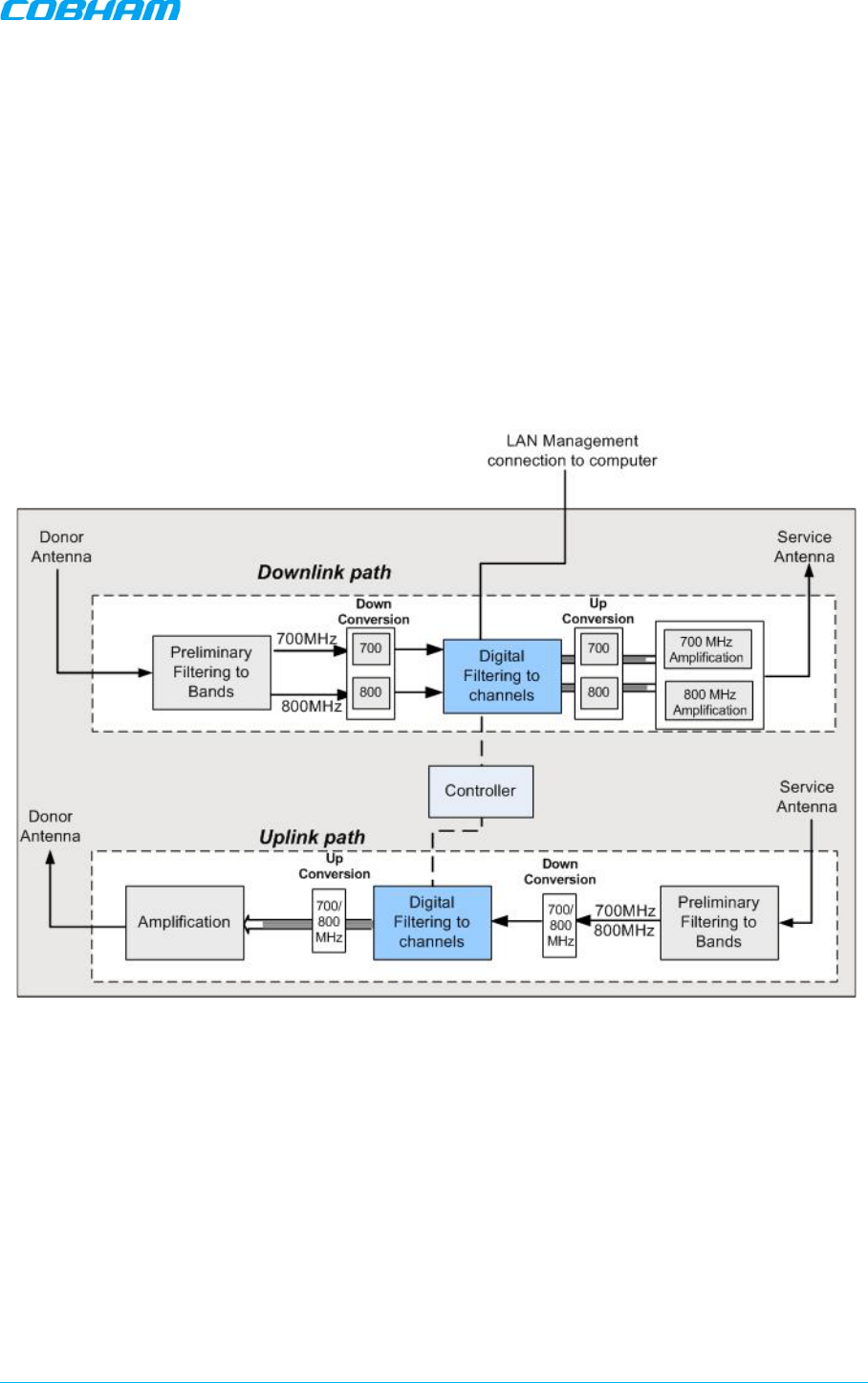
1.7 Functional Description
In the downlink, the signal from the Donor antenna is filtered to the 700MHz and 800MHz bands,
down converted, filtered according to the user defined (via GUI) channels, down converted and
amplified. The signals are then forwarded to the service antenna. In the uplink, the process is
reversed.
The maximum Analog Gain is 95dB, where Channel Gain between 0dB and 95dB is achieved by
reducing the Digital Gain from the System maximum Analog Gain; therefore, filtering and attenuation
is achieved through Digital Processing.
The block diagram showed in the figure below illustrates the overall functionality of the D-MBR PS
NFPA Signal Boosters and shows the operation flow in the downlink path and the uplink path.
Figure 1-4 Signal Booster - Block Diagram
D-MBR 3707-3708 PS NFPA CLASS B SIGNAL BOOSTER
PRODUCT DESCRIPTION AND USER’S MANUAL
www.cobham.com/wireless Cobham Wireless – Coverage Date: 6-Set-15
Page | 6 Doc. No. 00060CDUM Rev. 1.0
2 ANTENNA REQUIREMENTS
This section describes the information and specifications required for Donor and Service antennas.
WARNINGS!!
• The installer is held accountable for implementing the rules required for deployment.
• Good engineering practice must be used to avoid interference.
• Output power should be reduced to solve any IMD interference issues.
2.1 Donor Antenna
The Base (Donor) antenna is usually installed outdoors and is either a directional antenna such as a
Yagi or a Panel antenna.
2.1.1 Required Antenna Information
You will require the following antenna information:
• Antenna type and characteristics
• Height
• Length and type of coaxial cable required for connecting the Donor antenna to the Signal Booster
and the attenuation.
2.1.2 Donor Antenna specifications
• Yagi type or similar – 10 to 15 dBi gain, very sharp beam pointed to the BTS.
• Cable and jumper loss is at least 2dB.
• The required Base signals should be the dominant signals; at least 6 dB higher power than other
signals.
• Example of antenna's typical specifications:
Gain: 8 dBd (=10.1 dBi)
VSWR: < 1:5:1
Impedance: 50 ohm
2.1.3 Installation Criteria
NOTE: Verify that the antennas meet requirements described in the previous sections..
Installation requirements:
• Select a location for the Donor antenna and verify that there is the signal strength is strong
enough at that location.
• Install the Donor Antenna at the designated height.
• The antenna should point to the direction of the base station for maximum input power.
• Verify that the antenna is in the base stations line of sight (raise the antenna if necessary).
• Install the donor antenna at a higher level (i.e. floor) than the mobile antenna.
• Must be installed at a minimum distance of 1 meter from any personnel within the area.

D-MBR 3707-3708 PS NFPA CLASS B SIGNAL BOOSTER
PRODUCT DESCRIPTION AND USER’S MANUAL
Cobham Wireless – Coverage Date: 6-Set-15 www.cobham.com/wireless
Doc. No. 00060CDUM Rev. 1.0 Page | 7
2.2 Service Antenna
The Service antenna type depends on whether the Signal Booster is installed indoors or outdoors.
2.2.1 Required Information
The following antenna requirements, specifications and site considerations should be met.
• Type of installation – indoor or outdoor
• Service area size
• Height at which antenna(s) is/are installed
• Antenna type and characteristics
• Length and type of coaxial cable required for connecting the Service antenna to the Signal
Booster and the attenuation.
2.2.2 Indoor Installations
2.2.2.1 Recommended Antennas
The following describes the requirements for an omni-directional mobile used for indoor applications.
Specifications:
• One or a combination of the following antennas can be used: Ceiling Mount Patch antenna, Wall
Mount Patch antenna, Corner Reflector.
• Omni directional antenna with a 0 to 2 dBi typical gain, or wide beam with up to 10 dBi gain.
• Example of omni-directional antenna specifications:
Gain: 0 to 2 dBi
VSWR: < 2:1
Impedance: 50 ohm
• Choose an antenna with high side lobe attenuation that allows maximum isolation from the
service/ mobile antenna.
• A minimum of 5 such antennas must be connected to the Signal Booster with cables and
splitters.
• The maximum EIRP from each antenna shall not exceed 3W.

D-MBR 3707-3708 PS NFPA CLASS B SIGNAL BOOSTER
PRODUCT DESCRIPTION AND USER’S MANUAL
www.cobham.com/wireless Cobham Wireless – Coverage Date: 6-Set-15
Page | 8 Doc. No. 00060CDUM Rev. 1.0
2.2.2.2 Installation Criteria
Installation requirements:
• An indoor antenna should be installed at a convenient location. It should be free of metallic
obstruction.
• Install the Service Antenna at the designated height and tune it roughly toward the Service
coverage area.
• Installation of this antenna must provide a minimum separation distance of 28 cm from any
personnel within the area.
Note: If the power is divided into more than 5 antennas that have a large coverage area than the
separation distance can be less than 28 cm.
• Cable and jumper loss is at least 2dB.
2.2.3 Outdoor Installations
For applications in which the Mobile antenna is installed outdoors, the antenna type is chosen
according to the available infrastructure (single-pole or horizontal installation). In addition, isolation
between the donor and service antennas must be taken into account when selecting the location of
the antennas.
2.2.3.1 Recommended Antennas
The antenna type depends on the installation:
• For vertical
Single Pole
installations a high side lobe suppression antenna is required.
• For horizontal installations either on two separate poles or on two sides of one building a high
front to back ratio antenna is required.
Specifications:
• Maximum antenna gain for outdoor operation 9dBi.
• Cable and jumper loss is at least 2dB.
• [Gain Antenna – Cable loss] should not exceed 7dB
Installation requirements:
• Installation of this antenna must provide a minimum separation distance of 62 cm from any
personnel within the area.
NOTE: The Single Pole and Horizontal Installations are described in section 2.2.3.2 and 2.2.3.3.
D-MBR 3707-3708 PS NFPA CLASS B SIGNAL BOOSTER
PRODUCT DESCRIPTION AND USER’S MANUAL
Cobham Wireless – Coverage Date: 6-Set-15 www.cobham.com/wireless
Doc. No. 00060CDUM Rev. 1.0 Page | 9
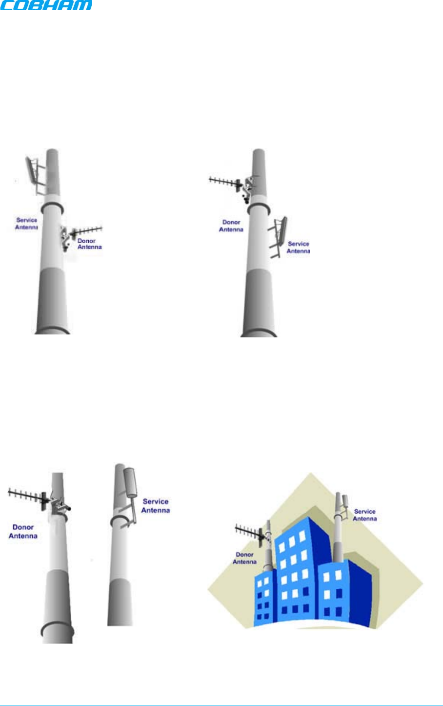
2.2.3.2 Vertical Separation Configuration
The Vertical Separation configuration is recommended in cases where the BTS is relatively far and
the service coverage area is relatively small.
In Vertical Separation configuration, the Donor antenna can be installed either above or below the
Service antenna on a COMMON tower. It is required to set the distance between them to achieve
maximum isolation.
The figures below illustrate the installations.
Figure
2-1. Service above Donor Antenna Figure
2-2. Donor above Service Antenna
2.2.3.3 Horizontal Separation Configuration
In the Horizontal Separation configuration, the Donor and Service antennas are installed on two
separate towers at approximately the same height. The towers can be either on the same side of the
building or on different sides of the building as shown below.
Figure
2-3. Donor and Service Antennas
Installed on Separate Towers
Figure
2-4. Service and Donor Antennas Installed
on Opposite Sides of the Building
D-MBR 3707-3708 PS NFPA CLASS B SIGNAL BOOSTER
PRODUCT DESCRIPTION AND USER’S MANUAL
www.cobham.com/wireless Cobham Wireless – Coverage Date: 6-Set-15
Page | 10 Doc. No. 00060CDUM Rev. 1.0
3 INSTALLING THE SIGNAL BOOSTER
This chapter describes the installation of the D-MBR 3707-3708 PS NFPA booster. For installations
that include the Feeder and Battery Charger, refer to Chapter-4 for the installations instructions.
WARNINGS!!!
• Follow all local safety regulations when installing the Signal Booster.
• Only qualified personnel are authorized to install and maintain the Signal Booster.
• Follow Electro-Static Discharge (ESD) precautions.
NOTE: If included in the installation), the Battery Charger is installed adjacent to the Booster. Refer
to chapter 4 for instructions on installing the Battery Charger.
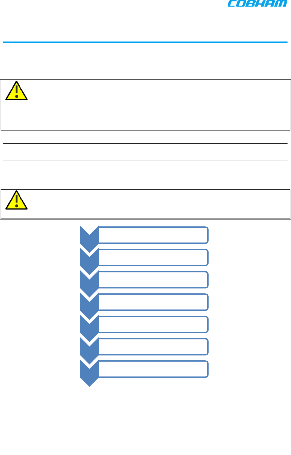
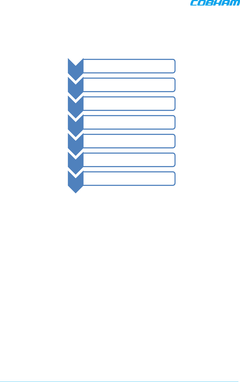
3.1 Overview of the Physical Installation Procedure
WARNING!! Be sure to perform the power supply AFTER antennas are connected,
otherwise damage may be caused to the system.
Figure 3-1 Physical Installation Workflow
Step-1 •Installation Location
Step-2 •Unpacking
Step-3 •Mounting
Step-4 •Grounding
Step-5 •Antenna connections
Step-6 •Power connections
Step-7 •Alarm connections
D-MBR 3707-3708 PS NFPA CLASS B SIGNAL BOOSTER
PRODUCT DESCRIPTION AND USER’S MANUAL
Cobham Wireless – Coverage Date: 6-Set-15 www.cobham.com/wireless
Doc. No. 00060CDUM Rev. 1.0 Page | 11
3.2 Pre-installation Requirements
This section lists and details the following pre-installation requirements:
• Required BTS information
• Choosing the Booster installation location
3.2.1 Required BTS Information
Required BTS Information
• BTS channels
• BTS output power per channel
• BTS antenna gain
• BTS antenna height and distance from antenna site
3.2.2 Installation Location Criteria and Environment
WARNING!! The signal booster must always be installed vertically with the connectors on
the underside for protection (see 3.4.4). Horizontal installation on a bench for long time may cause
damage to the signal booster due to over-heating.
The following criteria should be considered when selecting the Signal Booster installation site
location:
• Application type – indoor or outdoor
• Distance from antenna site and BTS antenna height.
It is recommended that the installation location be as close as possible to the antenna site in
order to maintain the cable loss to a minimum.
• General surroundings and accessibility of location
• In outdoor applications it is recommended to install a cabinet or a shielding sunroof for further
protection against weather wear.
• Use a suitable mounting surface, such as a flat back rigid wall.
• The Signal Booster is convection cooled so airflow and alternation should be possible.
• Install the Signal Booster in a shielded, ventilated, and easy-to-reach area – preferably at eye
level.
• Verify that there is a minimum of a 50 cm (20”) radius of space around the Signal Booster and 1
meter in depth (3 ft) in order to allow the unit door to swing completely open, enabling easy
access to the signal booster for maintenance and on-site inspection.
• Follow Electro-Static Discharge (ESD) precautions.
• Install the Signal Booster close to the service area to monitor the output power and noise figure.
• Verify that ambient temperature of the environment does not exceed 50°C (122°F)
D-MBR 3707-3708 PS NFPA CLASS B SIGNAL BOOSTER
PRODUCT DESCRIPTION AND USER’S MANUAL
www.cobham.com/wireless Cobham Wireless – Coverage Date: 6-Set-15
Page | 12 Doc. No. 00060CDUM Rev. 1.0
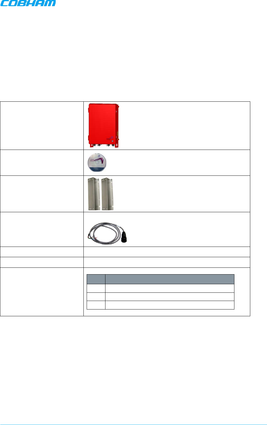
3.3 Booster Unpacking and Package Contents
Upon receiving the D-MBR-PS-NFPA Signal Booster, perform the following:
1. Examine the shipping container for damage before unpacking the unit.
2. Perform a visual inspection to reveal any physical damage to the equipment.
3. Verify that all of the items listed in the packing list are included. Otherwise contact yourCobham
Wireless service representative.
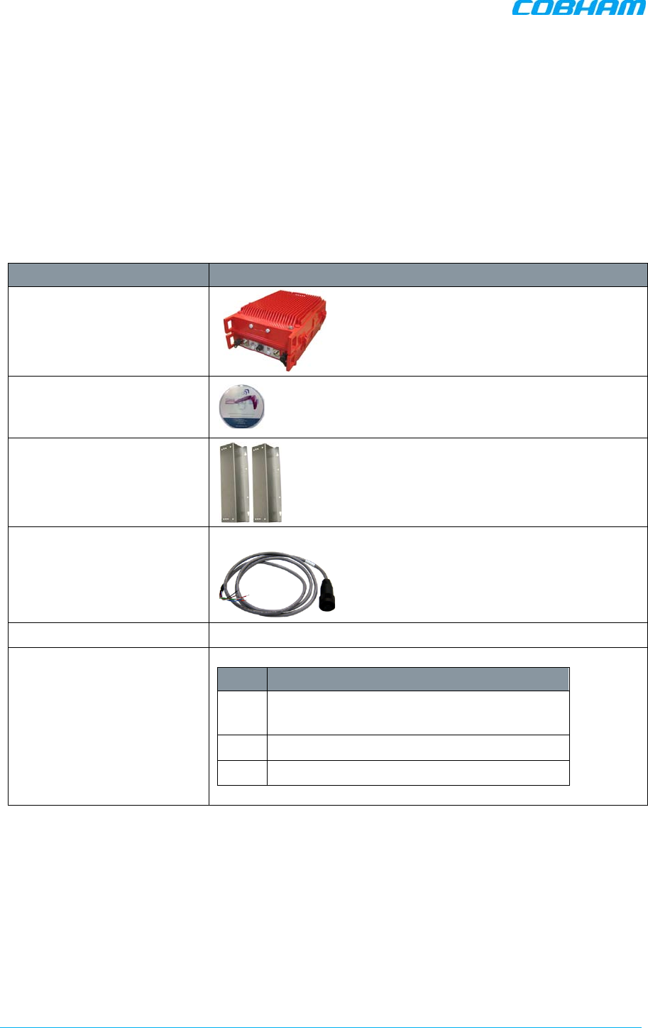
Booster Package Contents
Item Description
D-MBR Booster
CD containing User’s Manual
and USB driver
Mounting Brackets
1 x Alarms Connector
Circular 8 Pin (P/N 30WEC70500)
DC Cable
Additional (supplied)
installation components:
Qty. Description
4x M8x12 bolts for securing the Booster to the
brackets
1x Insex tool for bolts
1 x key
D-MBR 3707-3708 PS NFPA CLASS B SIGNAL BOOSTER
PRODUCT DESCRIPTION AND USER’S MANUAL
Cobham Wireless – Coverage Date: 6-Set-15 www.cobham.com/wireless
Doc. No. 00060CDUM Rev. 1.0 Page | 13
3.4 Mounting the System
Note the following:
• The mounting procedure is identical for both INDOOR and OUTDOOR installations.
• The mounting procedure is identical for both BOOSTER and BATTERY CHARGER (where relevant)
installations.
• The weight of the BOOSTER requires that TWO PEOPLE mount the unit on the wall.
• WASHERS are NOT SUPPLIED with the unit to be mounted.
• In addition to the bracket assembly, it is recommended to use additional fixings – an example is
given in section 3.4.4.
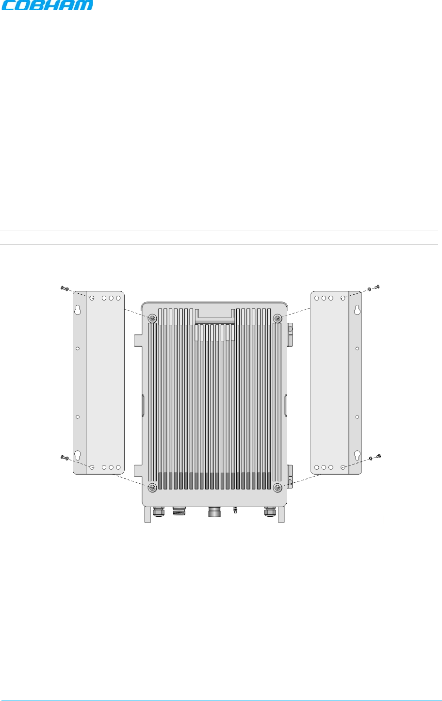
3.4.1 Bracket Assembly
NOTE: Assemble the brackets to the unit.
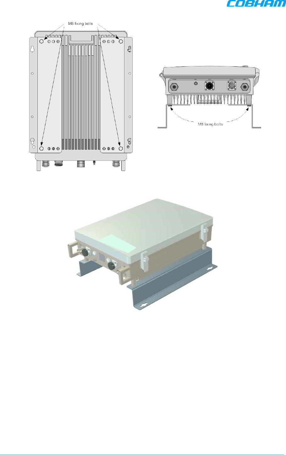
• Fix mounting brackets to the unit – use the supplied four M8 bolts and spring washers. Fix
mounting brackets to unit using M8 fixing bolts and supplied spring washers
Figure 3-2: Fix mounting brackets to Unit
D-MBR 3707-3708 PS NFPA CLASS B SIGNAL BOOSTER
PRODUCT DESCRIPTION AND USER’S MANUAL
www.cobham.com/wireless Cobham Wireless – Coverage Date: 6-Set-15
Page | 14 Doc. No. 00060CDUM Rev. 1.0
Figure 3-3: Mounting Plates Fixed to Unit (example)
Figure 3-4: Bracket Position
D-MBR 3707-3708 PS NFPA CLASS B SIGNAL BOOSTER
PRODUCT DESCRIPTION AND USER’S MANUAL
Cobham Wireless – Coverage Date: 6-Set-15 www.cobham.com/wireless
Doc. No. 00060CDUM Rev. 1.0 Page | 15
3.4.2 Wall Marking and Drilling
NOTE: In addition to the bracket assembly, it is recommended to use additional fixings – an example
is given in section 3.4.4.
• The unit wall mount brackets assembly should be fixed to a solid wall (these include brickwork,
blockwork, and concrete.);
• To provide secure fixing to a solid wall, the most common method is drilling and plugging. The
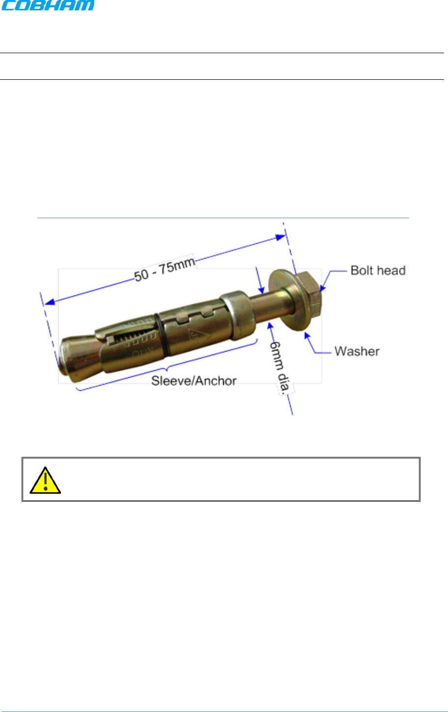
size of fixing is dependent on the item to be fixed and the nature of the wall, The unit should be
fixed with mild steel, M6 (50mm to 75mm) rawlbolts or similar.
• In addition to the bracket assembly, it is recommended to use additional fixings – an example is
given in section 3.4.4.
• Care must be taken to ensure the alignment of the four fixings. A spirit level or plumb line should
be used to ensure horizontal/vertical alignment.
Figure 3-5: M6 Rawlbolt – recommended for wallmount.
IMPORTANT!! Always check that there are no pipes or cables hidden in the
wall beneath the area to be drilled. Various pipe and cable detectors are
available for this type of inspection.
D-MBR 3707-3708 PS NFPA CLASS B SIGNAL BOOSTER
PRODUCT DESCRIPTION AND USER’S MANUAL
www.cobham.com/wireless Cobham Wireless – Coverage Date: 6-Set-15
Page | 16 Doc. No. 00060CDUM Rev. 1.0
To mark and drill the wall
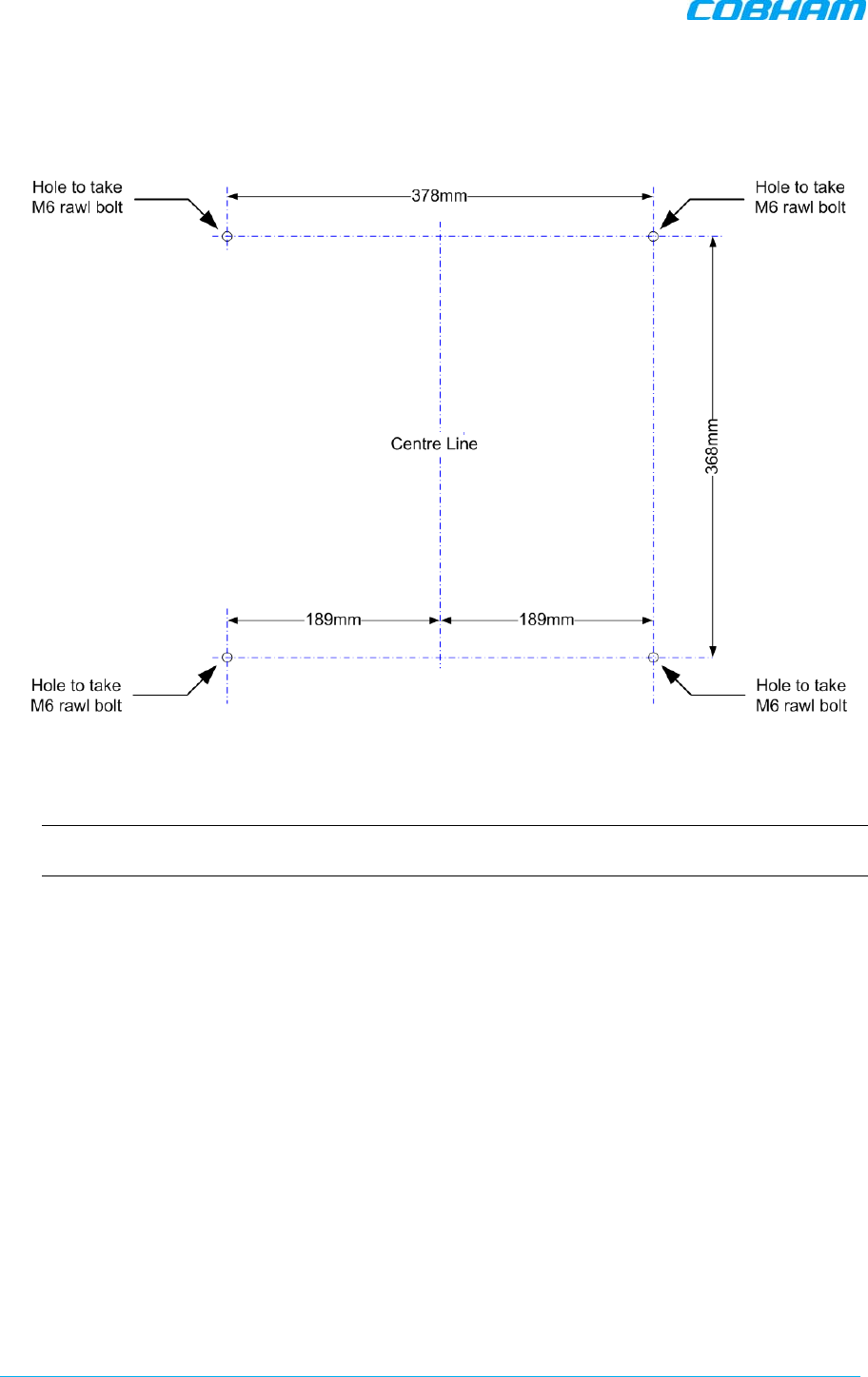
1. Mark out the fixing centres of the Booster on the chosen wall. The unit dimensions are shown
below.
Figure 3-6: Fixing Centers
2. Mark and drill the wall with the correct size masonry bit as specified by the fixing manufacturer.
NOTE: It is good practice to wear goggles to protect your eyes from flying debris when using
power tools.
3. Hold the drill bit against the mark and begin drilling slowly so that the bit does not wander from
the position. The wall should be drilled to a depth which is sufficient to accommodate the full
length of the fixing.
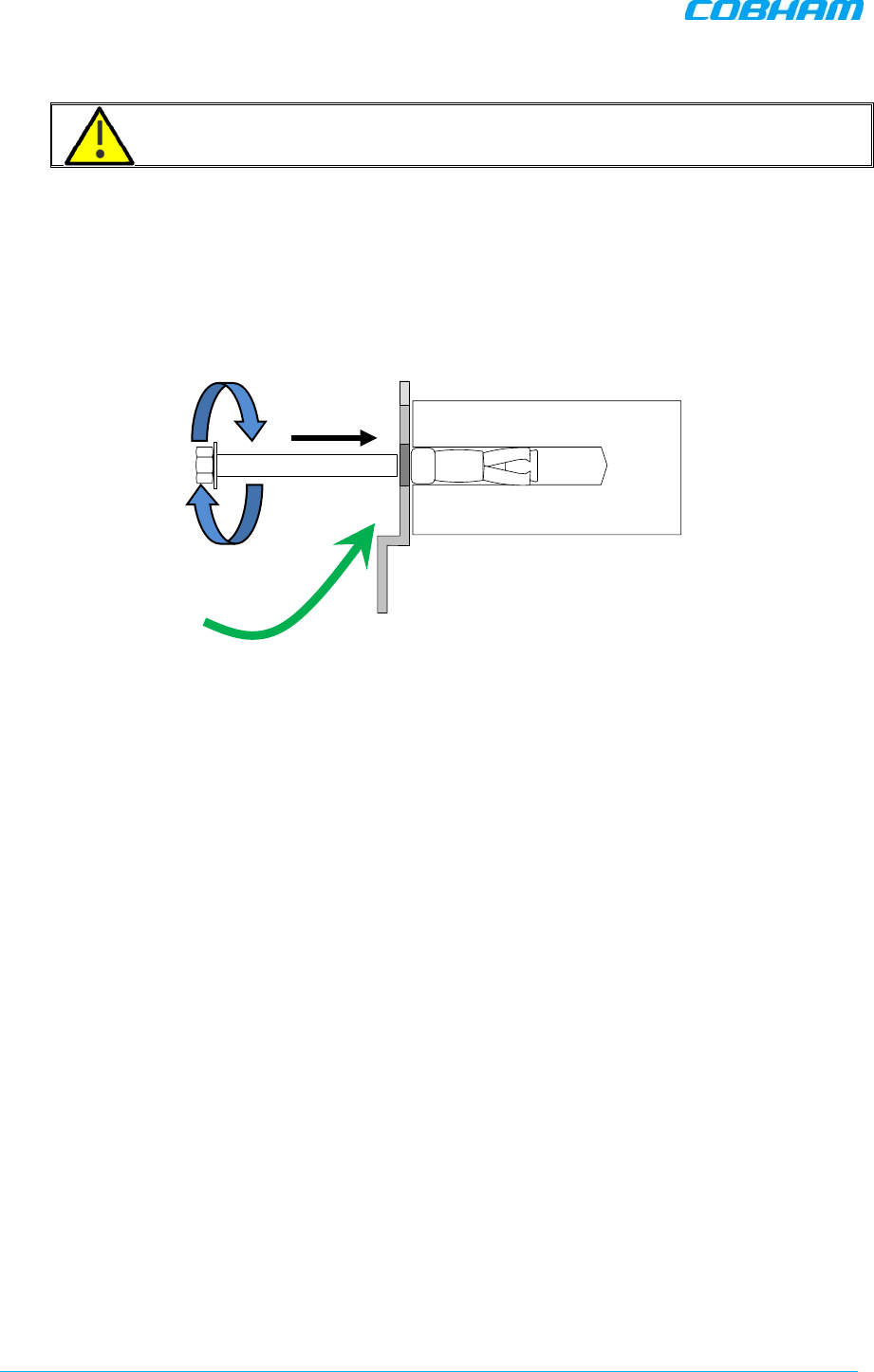
4. Insert the fixings so that the top of the sleeve/anchor section is level with the wall surface.

D-MBR 3707-3708 PS NFPA CLASS B SIGNAL BOOSTER
PRODUCT DESCRIPTION AND USER’S MANUAL
Cobham Wireless – Coverage Date: 6-Set-15 www.cobham.com/wireless
Doc. No. 00060CDUM Rev. 1.0 Page | 17
5. Gently tighten the bolt by hand so that the anchor section of the fixing expands and grips the
inside of the hole.
Figure 3-7: Inserting Fixing and Tightening.
6. As the bolt pulls its way in, the sides of the anchor section are forced outwards, gripping the
surrounding surface.
Figure 3-8: Anchor Sides Pushed Outwards.
7. Once all four fixings are in place, carefully withdraw the four bolts.
Figure 3-9: Withdraw Bolts.
D-MBR 3707-3708 PS NFPA CLASS B SIGNAL BOOSTER
PRODUCT DESCRIPTION AND USER’S MANUAL
www.cobham.com/wireless Cobham Wireless – Coverage Date: 6-Set-15
Page | 18 Doc. No. 00060CDUM Rev. 1.0
3.4.3 Mount the Unit
CAUTION!!! It is recommended that two people lift the unit since (depending on
the unit) it may weigh between 20 and 38 kg (44 and 84 lb).
To mount the unit
• Align unit with the four fixings. Great care should be exercised here as the Booster is very heavy.
(A suitably rated heavy duty scissor lift table/trolley may be suitable for this operation.)
• Once the unit is held in the chosen position, carefully insert the fixing bolts through the mounting
lugs of the unit and into the sleeve/anchor sections of the fixing in the wall and tighten the bolts.
• The unit needs to be mounted tightly to eliminate vibration.
Figure 3-10: Mount Unit
Align
unit and
secure bolts
D-MBR 3707-3708 PS NFPA CLASS B SIGNAL BOOSTER
PRODUCT DESCRIPTION AND USER’S MANUAL
Cobham Wireless – Coverage Date: 6-Set-15 www.cobham.com/wireless
Doc. No. 00060CDUM Rev. 1.0 Page | 19
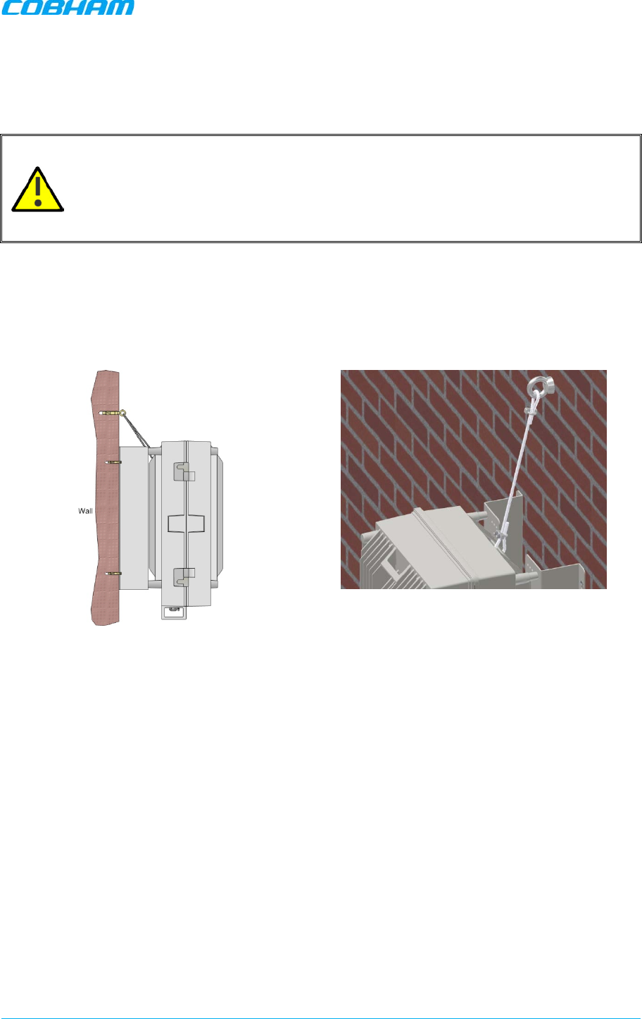
3.4.4 Recommended Additional Fixing
SUGGESTED PRECAUTIONARY MEASURE!!
•
Brackets are provided to securely mount the Booster on the wall; however, as an
ADDITIONAL precautionary measure, it is recommended to further secure the Booster to the
wall (in addition to the bracket).
•
This can be done using any appropriate method.
•
It is the installer’s responsibility to ensure the Booster is installed in a secure manner.
The following figures provide EXAMPLES of additional fixings. In the examples, support is provided in
the form of a CABLE HARNESS LOOP that is looped around the Booster handle and secured to the
wall or part of the building support structure.
Figure 3-11: Example 1 of Additional Fixing to Wall
D-MBR 3707-3708 PS NFPA CLASS B SIGNAL BOOSTER
PRODUCT DESCRIPTION AND USER’S MANUAL
www.cobham.com/wireless Cobham Wireless – Coverage Date: 6-Set-15
Page | 20 Doc. No. 00060CDUM Rev. 1.0
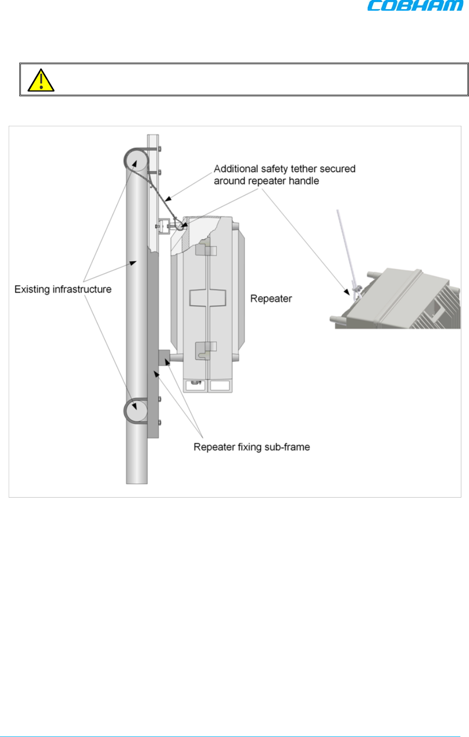
Another example is of a unit installed on a stadium gantry. Again, the support can be in the form of a
cable harness loop, using the handle of the unit and part of the gantry structure.
ATTENTION!! Any other SECURE method can be used.
Figure 3-12: Example 2 of Additional Fixing to Gantry
D-MBR 3707-3708 PS NFPA CLASS B SIGNAL BOOSTER
PRODUCT DESCRIPTION AND USER’S MANUAL
Cobham Wireless – Coverage Date: 6-Set-15 www.cobham.com/wireless
Doc. No. 00060CDUM Rev. 1.0 Page | 21
3.5 Grounding
NOTE: The grounding procedure is identical for both BOOSTER and BATTERY CHARGER.
3.5.1 Grounding Wire Requirements
Requirements for grounding wires
• Protective grounding conductor - should be aluminum with cross-section 10AWG.
• Lug of the protective grounding conductor - should be aluminum
• Washers and screw - should be high Cr stainless steel, or 12% Cr stainless steel, or Cr on, Ni on
steel, tin on steel
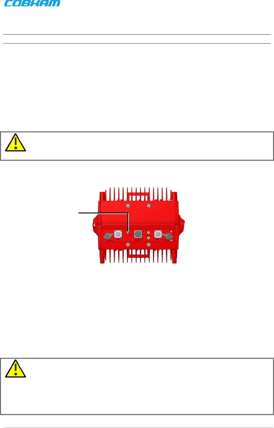
3.5.2 Grounding Units
WARNING!! Ground the Signal Booster with the booster’s grounding bolt. Do not use the
grounding bolt to connect external devices.
Connect the grounding wire to the GND lug on each unit as shown below.
Figure 3-13 Booster GND Lug
3.6 Antenna Connections and Guidelines
This section describes the antenna connection requirements, guidelines and procedure. It includes
the following procedures:
• Verifying isolation between Donor and Service antennas
• Verifying link between BTS and donor antenna
• RF cable installation guidelines
• Connecting the antennas
CAUTION!!
• Do not connect the antenna cables to the Signal Booster before verifying the installation
parameters - specifically the isolation between the antennas.
• DO NOT POWER-ON the Signal Booster without either the antennas being connected or the
antenna connections terminated with dummy loads.
GND LUG

D-MBR 3707-3708 PS NFPA CLASS B SIGNAL BOOSTER
PRODUCT DESCRIPTION AND USER’S MANUAL
www.cobham.com/wireless Cobham Wireless – Coverage Date: 6-Set-15
Page | 22 Doc. No. 00060CDUM Rev. 1.0
3.6.1 Verifying Isolation between Donor and Service Antennas
Note the following:
• The isolation between the Donor and Service antennas is critical especially for high gain, outdoor
applications.
• For proper operation of the Signal Booster, it is recommended that the isolation between the
Donor and Service antennas be at least 15dB higher than the Signal Boosters set gain. (Lower
isolation can lead to high in-band ripple, oscillations and low signal quality.)
• Ensure proper vertical or horizontal distance separation between Donor and Service antennas
To measure the isolation, proceed as follows:
1. Inject a known signal from a signal generator into one antenna (preferably the Donor antenna).
2. Measure the coupled output from the Service antenna, using the Spectrum analyzer and LNA if
applicable.
3. Perform this procedure across the frequency range of both the Uplink and Downlink bands.
4. Register the lower result for system operation.
3.6.2 Verifying the Link between the BTS and the Signal Booster
This test checks the signal strength from the BTS antenna to the Signal Booster.
Proceed as follows:
1. Using a Spectrum analyzer, measure the received signal from BTS at the Donor antenna port
near the Signal Booster.
2. Adjust the Donor antenna direction to receive the maximum signal strength.
3. Compare the received signal strength with the calculated signal strength from the design phase.
In case of discrepancy, check for one of the following:
• Antenna out of direction
• Antenna tuned to side lobe instead of main lobe
• Antenna connector or antenna cable faulty
• Line-of-sight problem (obstruction), etc.
4. Register the signal strength of the downlink channel for the system operation phase.
D-MBR 3707-3708 PS NFPA CLASS B SIGNAL BOOSTER
PRODUCT DESCRIPTION AND USER’S MANUAL
Cobham Wireless – Coverage Date: 6-Set-15 www.cobham.com/wireless
Doc. No. 00060CDUM Rev. 1.0 Page | 23
3.6.3 RF Cable Installation Guidelines
Note the following:
• For all coaxial connections to/from the Signal Booster - high performance, flexible, low loss 50
ohm coaxial communications cable.
• All cables shall be weather-resistant type.
• If the coaxial cables are NOT weather-resistant type: wrap the exterior coaxial cables with
insulation and holding tape (Type 3M Rubber splicing tape) for environmental protection and to
ensure longer lifetime.
• Cable length - determined by the Signal Booster installation plan. When calculating the cable
length, take into account excess cable slack so as not to limit the insertion paths.
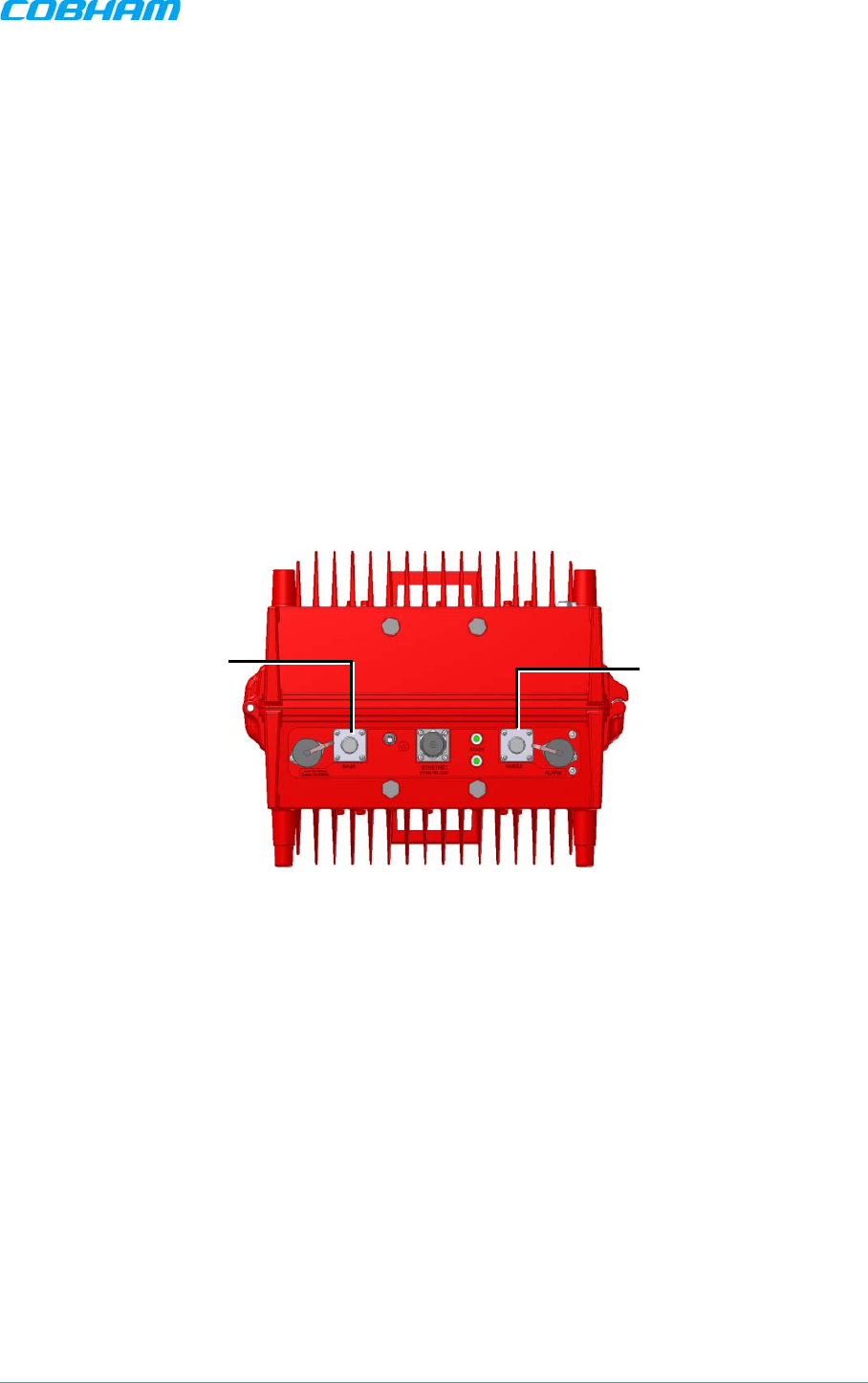
3.6.4 Connecting Antennas
• Connect the Donor and Service antennas.
• Verify all RF connectors are tightened and the cables and antennas are secured.
Figure 3-14 Booster GND Lug
Donor antenna
Service antenna
D-MBR 3707-3708 PS NFPA CLASS B SIGNAL BOOSTER
PRODUCT DESCRIPTION AND USER’S MANUAL
www.cobham.com/wireless Cobham Wireless – Coverage Date: 6-Set-15
Page | 24 Doc. No. 00060CDUM Rev. 1.0
3.7 Connecting Power and Power-Up
CAUTION!!
• DO NOT POWER-ON the Signal Booster without either the antennas being connected or the
antenna connections terminated with dummy loads.
• This equipment can either be installed indoors or outdoors. When installing OUTDOORS, wet
conditions increase the potential for electric shock when installing or using electrically powered
equipment. To prevent electrical shock when installing or modifying the system power wiring,
disconnect the power source before working with uninsulated wires or terminals.
The Signal Booster operates from a 48VDC power source – either UPS or Battery Charger (ordered
separately).
NOTE: The AC Feeder Battery Charger installation and connections are described in Chapter-4.
To connect the power
1. For installations with UPS:
• Verify the UPS is set up.
• Connect 48VDC from the UPS or AC to DC converter (depending on the installation)
to the Booster Power Connector
2. For installations with the Battery Charger:
• Verify the Charger is installed properly – refer to Chapter-4 for the Charger
installation and connections.
• Connect the Battery Charger 48VDC output to Booster power connector.
3. Power-ON.
NOTE: During the Power Up process the CPU requires approximately four minutes to boot up.
Figure 3-15. D-MBR PS NFPA Power Connections
-
48V from AC to DC
converter (in case of UPS)
or from Battery Charger
D-MBR 3707-3708 PS NFPA CLASS B SIGNAL BOOSTER
PRODUCT DESCRIPTION AND USER’S MANUAL
Cobham Wireless – Coverage Date: 6-Set-15 www.cobham.com/wireless
Doc. No. 00060CDUM Rev. 1.0 Page | 25
3.8 Booster Dry-Contact Alarm Connections
This section describes the dry-contact alarm connections for the
booster
.
The D-MBR and its power source (UPS or Battery Charger), each provide dry-contact alarms towards
the Fire Department Control Box. (In installations with UPS, refer to your UPS manual for instructions
on dry-contact alarm connections to the Fire Department Control box).
Note the following:
• The alarms can be connected any time, before or after the system is powered-on.
• The Charger alarm connections are described in section 4.4.7.
• Optionally, the Battery Charger Fail and AC Input Fail from the UPS or Charger can be connected
to the Booster alarms (requires GUI configuration as well.
Figure 3-16. D-MBR PS NFPA with Charger Architecture
3.8.1 Load Restrictions
3.8.1.1 Alarm Dry Contact Output Restrictions
• Maximum switching voltage: 220 VDC, 125 VAC
• Maximum switching current: 2A
3.8.1.2 External Alarm Input Restrictions
• Maximum repetitive reverse voltage: 28 V
• Impedance load: 470 Ohm
“0” - 0V
“1” - 3.8V - 28V
D-MBR 3707-3708 PS NFPA CLASS B SIGNAL BOOSTER
PRODUCT DESCRIPTION AND USER’S MANUAL
www.cobham.com/wireless Cobham Wireless – Coverage Date: 6-Set-15
Page | 26 Doc. No. 00060CDUM Rev. 1.0
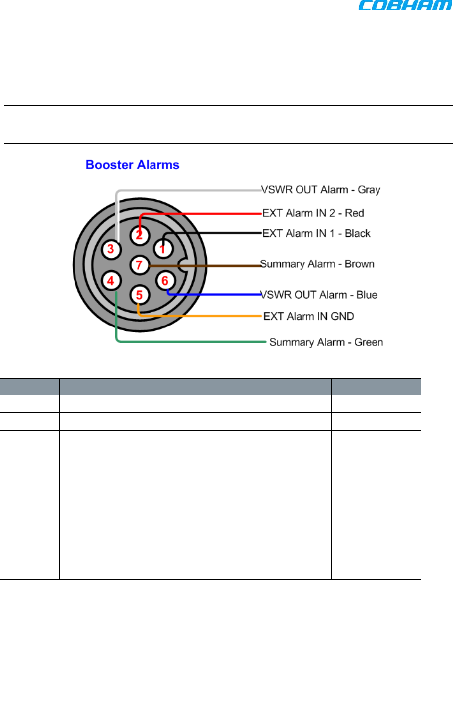
3.8.2 Booster Alarm Connector Pinout
Each alarm status is recognized by a separate wire-pair, where the colored wires are internally
connected with a 4.7 K ohm resistor (serves as a pull up resistor to +5V. The following figure shows
the Alarm connector pinout.
NOTE: The two external alarms can be used to connect dry-contacts BAT LOW and AC Input Fail
from either the UPS or Battery Charger. It is required to configure connected external alarms
according to section 5.5
Figure 3-17. D-MBR Alarm Connector Pinout
Pin No. Signal Name Wire Colour
1 External Alarm #1 Black
2 External Alarm #2 Red
3 Dry Contact VSWR Alarm (Normally Closed)* White
4 Dry Contact Summary Alarm (Normally Closed)**
Triggered under one of the following conditions:
• PA current from FF
• Temperature High or Built-In-Test
• Power failure
Green
5 GND for External Alarm Orange
6 Dry Contact VSWR Alarm (Normally Closed)* Blue
7 Dry Contact Summary Alarm (Normally Closed)** Brown
*Dry Contact VSWR alarm connection is supported by a pair of wires (3,6). Also, Pins 3,6 can indicate Power Up
for approximately 1 minute when system is powered up by closing contacts 3,6.** Dry Contact Summary alarm
connection is supported by a pair of wires (4,7)
D-MBR 3707-3708 PS NFPA CLASS B SIGNAL BOOSTER
PRODUCT DESCRIPTION AND USER’S MANUAL
Cobham Wireless – Coverage Date: 6-Set-15 www.cobham.com/wireless
Doc. No. 00060CDUM Rev. 1.0 Page | 27
4 BATTERY CHARGER DESCRIPTION AND
INSTALLATION
For installations where UPS is not available, the AC Feeder and Battery Charger unit can be
purchased (see section 4.1 for ordering information).
The Feeder and Charger provides continuous power of 48 VDC by utilizing an external (customer
purchased) battery for backup in case power failure.
The Charger provides the following dry contact alarms (as defined in the NFPA standard): AC failure,
Charger failure and Low battery.
NOTE: Use only external batteries meeting the specifications given in section 4.4.6.
This section describes the Battery Charger Unit interfaces, the architecture of the installation and the
installation procedure.
Figure 4-1. AC Feeder and Battery Charger
4.1 Charger Ordering Information
IDENTIFICATION DESCRIPTION PART NUMBER
D-MBR 3707-3708
AC feeder and
battery charger
AC feeder and battery
charger for 200AH
batteries with NFPA and IFC compliant Alarm
Outputs and red painted case.
BATT-CHARGER-110VAC-
200AH-NFPA
D-MBR 3707-3708 PS NFPA CLASS B SIGNAL BOOSTER
PRODUCT DESCRIPTION AND USER’S MANUAL
www.cobham.com/wireless Cobham Wireless – Coverage Date: 6-Set-15
Page | 28 Doc. No. 00060CDUM Rev. 1.0
4.2 Charger Architecture
D-MBR installation with the Battery Charger is illustrated below. The Charger is AC powered. It
simultaneously provides a 48 VDC output power to the booster and charges the external battery
(external battery not provided).
The Charger supports three dry contact alarms that are connected to the Fire Department Control
Box:
• AC Input Fail*
• Low Battery
• Battery Charger Fail*
As long as the AC power source is available, the
Charger
provides 48 VDC to the booster and
maintains the external battery fully charged.
If the AC power source to the charger fails, the
external battery
provides the 48 VDC power to the
Booster and the
AC Input Fail
Charger alarm is activated.
Figure 4-2. D-MBR PS NFPA with Charger Architecture
*Optionally, Battery Charger Fail and AC Input Fail can be connected to the Booster alarm connector for
monitoring).
D-MBR 3707-3708 PS NFPA CLASS B SIGNAL BOOSTER
PRODUCT DESCRIPTION AND USER’S MANUAL
Cobham Wireless – Coverage Date: 6-Set-15 www.cobham.com/wireless
Doc. No. 00060CDUM Rev. 1.0 Page | 29
4.3 Charger Interfaces
This section describes the AC Feeder and Battery Charger interfaces.
Figure 4-3. D-MBR Charger Interfaces
Interface Description
AC IN 110 VAC power source input
DC OUT 48VDC, 12A max power connection to booster power input.
GND Ground connection
BATTERY Connection to external, re-chargeable 200H battery (see section 4.4.6 for
external battery requirements)
Charging time for full 200AH battery estimated to about 20hrs.
ALARMS
Three Dry contact alarms:
Battery Low – battery is not charged to the minimum value.
Charger Fail – battery charger failure
AC Input Fail – AC input is not detected.
See section 4.4.7 for pinout.
LED’S AC in Green – AC input detected (Off if AC input is not detected)
Battery Green - battery is activated (due to no AC input)
DC out Green - DC out within range (Off – no DC out, or low DC
out)
Orange – Charger fail
VAC
Power source
LEDs
Connection to
external battery
Dry contact
alarms
-
48VDC out to
booster
GND
D-MBR 3707-3708 PS NFPA CLASS B SIGNAL BOOSTER
PRODUCT DESCRIPTION AND USER’S MANUAL
www.cobham.com/wireless Cobham Wireless – Coverage Date: 6-Set-15
Page | 30 Doc. No. 00060CDUM Rev. 1.0
4.4 Charger Installation Procedure
The Charger installation procedure consist of the following steps.
Figure 4-4 Physical Installation Workflow
4.4.1 Charger Installation Location
The charger is installed
adjacent
to the Booster either on the wall or
vertically
in a rack.
Refer to section 3.2.2 for the relevant location criteria.
Step-1 •Installation Location
Step-2 •Unpacking
Step-3 •Mounting
Step-4 •Grounding
Step-5 •Power Connections
Step-6 •Connection to External Battery
Step-7 •Alarm connections
D-MBR 3707-3708 PS NFPA CLASS B SIGNAL BOOSTER
PRODUCT DESCRIPTION AND USER’S MANUAL
Cobham Wireless – Coverage Date: 6-Set-15 www.cobham.com/wireless
Doc. No. 00060CDUM Rev. 1.0 Page | 31
4.4.2 Charger Unpacking and Package Contents
Upon receiving the D-MBR-PS-NFPA Signal Booster, perform the following:
1. Examine the shipping container for damage before unpacking the unit.
2. Perform a visual inspection to reveal any physical damage to the equipment.
3. Verify that all of the items listed in the packing list are included. Otherwise contact your Cobham
Wireless service representative.
Battery Charger Package Contents
Battery Charger
CD containing User’s Manual
and USB driver
Mounting Brackets
1 x Alarms Connector
Circular 8 Pin (P/N 30WEC70500)
AC Cable
DC Connector and cable
Additional (supplied)
installation components:
Qty.
Description
4x M8x12 bolts for securing the Booster to the brackets
1x Insex tool for bolts
2 x keys
4.4.3 Charger Wallmount Procedure
The charger is mounted next to the Booster and the mounting instructions are identical to that of the
Booster.
Refer to section 3.4 for instructions.
D-MBR 3707-3708 PS NFPA CLASS B SIGNAL BOOSTER
PRODUCT DESCRIPTION AND USER’S MANUAL
www.cobham.com/wireless Cobham Wireless – Coverage Date: 6-Set-15
Page | 32 Doc. No. 00060CDUM Rev. 1.0
4.4.4 Charger Grounding
The grounding procedure is identical to the Booster grounding procedure. Refer to section 3.5 for the
grounding instructions.
Figure 4-5 Battery Charger GND Lug
4.4.5 Charger Power Connections
To connect the Charger power:
• Connect Charger AC IN to 110 VAC power outlet
• Connect the Charger DC OUT to the Booster Power IN
Figure 4-6 Battery Charger Power Connections
GND LUG
To 110 VAC
outlet
To Booster -
48VDC
power input
D-MBR 3707-3708 PS NFPA CLASS B SIGNAL BOOSTER
PRODUCT DESCRIPTION AND USER’S MANUAL
Cobham Wireless – Coverage Date: 6-Set-15 www.cobham.com/wireless
Doc. No. 00060CDUM Rev. 1.0 Page | 33
4.4.6 Connection to External Battery
ATTENTION!! The Externally Battery must meet the following requirements:
• Valve-Regulated Lead-Acid (VRLA)
• Gelled Electrolyte (gel) and Absorbed Glass Mat (AGM) Batteries or LEAD ACID
Connect the external battery to the Charger Battery connector:
Figure 4-7 External Battery Connections
4.4.7 Charger Alarm Connections
The Charger supports three dry contact alarms that are connected to the Fire Department Control
Box:
• AC Input Fail*
• Low Battery
• Battery Charger Fail*
Figure 4-8. Charger Connections Architecture
*Optionally, Battery Charger Fail and AC Input Fail can be connected to the Booster alarm connector for
monitoring).
Connection to
External Battery
D-MBR 3707-3708 PS NFPA CLASS B SIGNAL BOOSTER
PRODUCT DESCRIPTION AND USER’S MANUAL
www.cobham.com/wireless Cobham Wireless – Coverage Date: 6-Set-15
Page | 34 Doc. No. 00060CDUM Rev. 1.0
4.4.7.1 Alarm Dry Contact Output Restrictions
• Maximum switching voltage: 220 VDC, 125 VAC
• Maximum switching current: 2A
4.4.7.2 External Alarm Input Restrictions
• Maximum repetitive reverse voltage: 28 V
• Impedance load: 470 Ohm
“0” - 0V
“1” - 3.8V - 28V
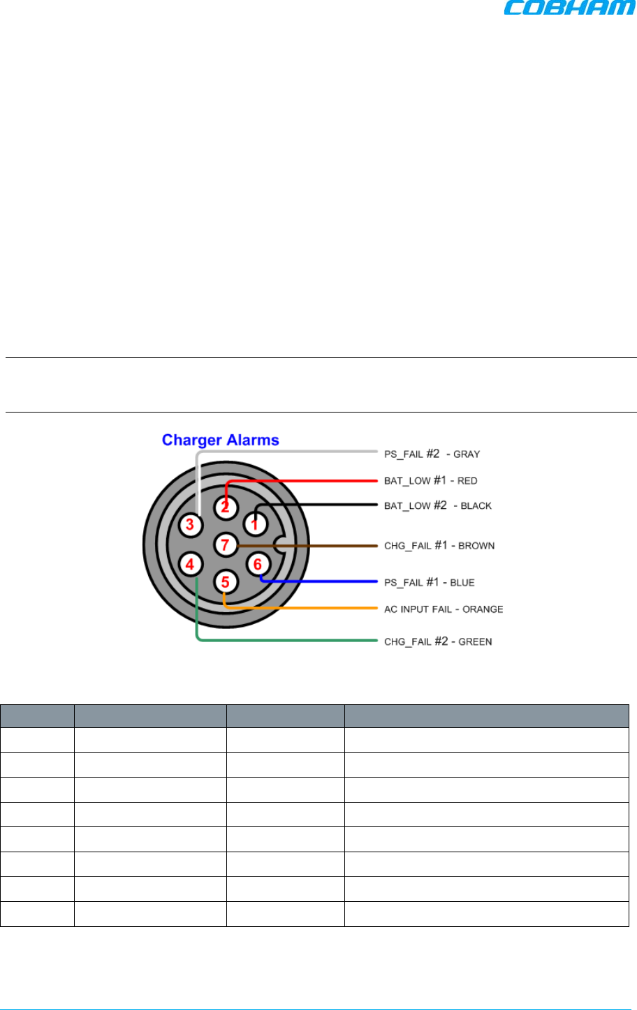
4.4.7.3 Charger Alarm Connector Pinout
Each alarm status is recognized by a separate wire-pair, where the colored wires are internally
connected with a 4.7 K ohm resistor (serves as a pull up resistor to +5V. The following figure shows
the Alarm connector pinout.
NOTE: The two external alarms can be used to connect dry-contacts BAT LOW and PSU Fail from
either the UPS or Battery Charger. It is required to configure connected external alarms according to
section 5.5
Figure 4-9. Charger Alarm Connector Pinout
Pin No. Signal Name Wire Colour Contact Type
1 BAT_LOW #2 Black dry-contact NC
2 BAT_LOW #1 Red dry-contact NC
3 PS_FAIL #2 Grey dry-contact NC
4 CHG_FAIL #2* Green dry-contact NC
5 AC INPUT FAIL* Orange NOT A DRY CONTACT – TTL TYPE
6 PS_FAIL #1* Blue dry-contact NC
7 CHG_FAIL #1* Brown dry-contact NC
TBD PSU_LOW_TO_BDA TBD NOT A DRY CONTACT – TTL TYPE
* Can be optionally connected to the following Booster Alarms connector Pin-1 (External Alarm #1) and Pin-2
(External Alarm #2) and Pin-5 (GND for both). Refer to section 3.8.2 for the Booster Alarm pinout.
D-MBR 3707-3708 PS NFPA CLASS B SIGNAL BOOSTER
PRODUCT DESCRIPTION AND USER’S MANUAL
Cobham Wireless – Coverage Date: 6-Set-15 www.cobham.com/wireless
Doc. No. 00060CDUM Rev. 1.0 Page | 35
5 SETUP AND COMMISSIONING
This section describes the setup procedures for the D-MBR Booster.
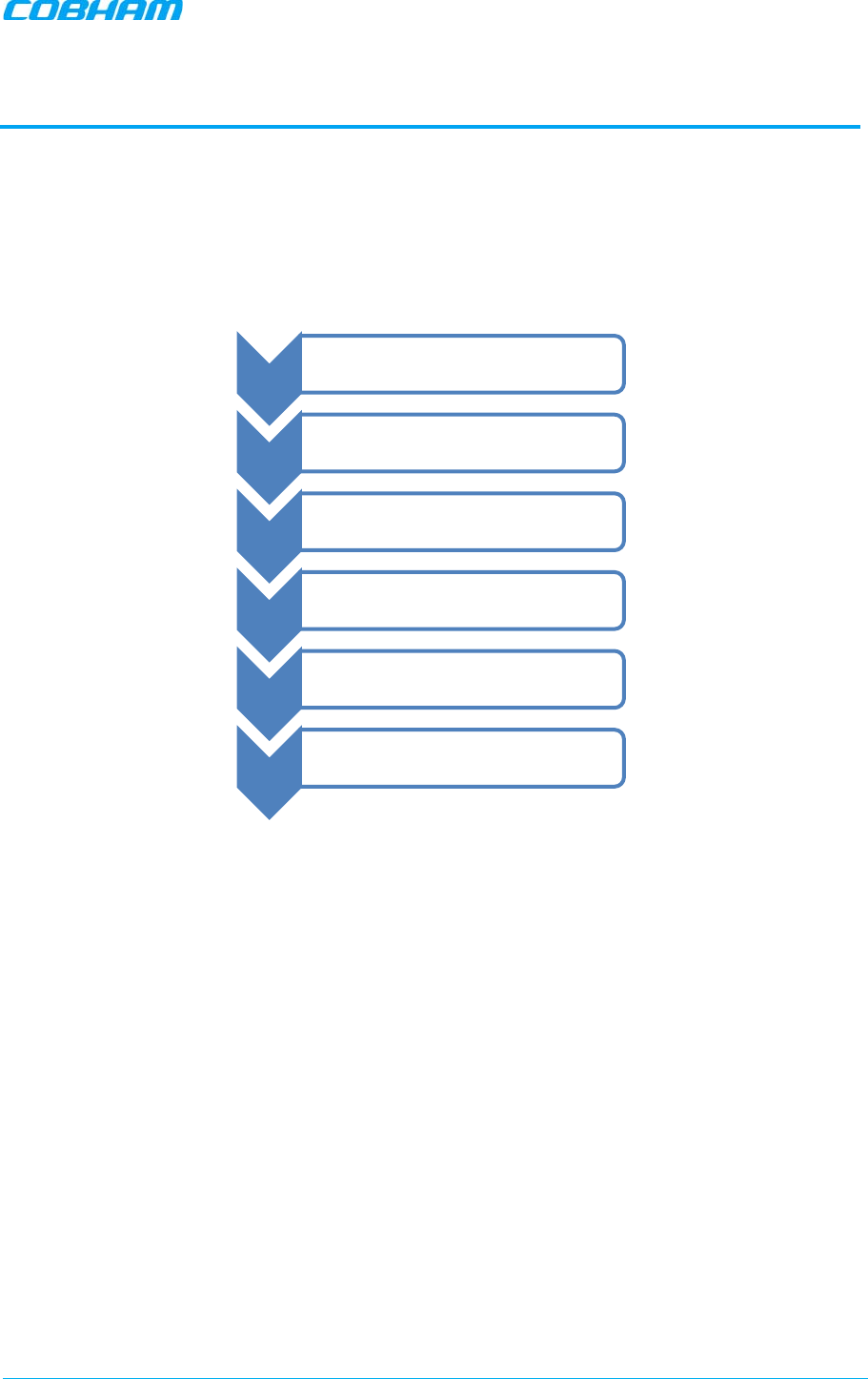
5.1 Overview of the Commissioning Procedure
The Booster is designed for simple plug-and-play operation, only requiring the setup of a number of
parameters via a local Web connection and verifying that the system is operating properly.
Figure 5-1 Commissioning Overview
Step-1 •Open a local session
Step-2 •RF Parameters
Step-3 •Date and Time
Step-4 •External Alarms Config
Step-5 •IP Address
Step-6 •Password Change
D-MBR 3707-3708 PS NFPA CLASS B SIGNAL BOOSTER
PRODUCT DESCRIPTION AND USER’S MANUAL
www.cobham.com/wireless Cobham Wireless – Coverage Date: 6-Set-15
Page | 36 Doc. No. 00060CDUM Rev. 1.0
5.2 Opening a Session to the Booster and
Navigating the GUI
This section describes how to open a first time local session to the Booster and how to navigate the
management Web GUI.
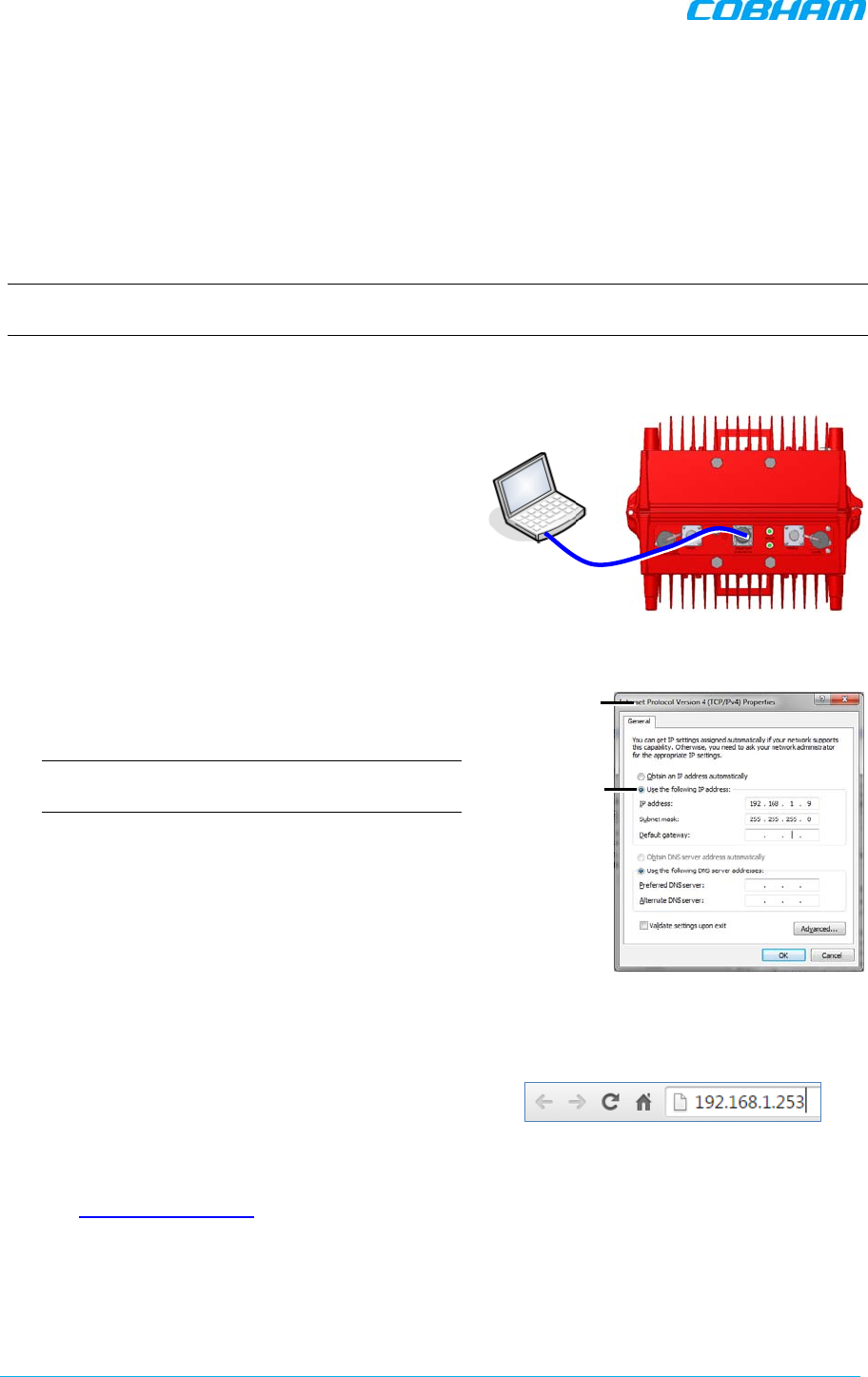
5.2.1 Open a First Time Local Web Session to the Booster
NOTE: To open a local session to the booster, the setup computer IP Address must be in the same
subnet as that of the Booster. The booster factor set IP Address is 192.168.1.253.
To open a local session to the booster:
1. Connect to the Boosters’ front panel Ethernet
port using the supplied Ethernet cable.
Figure
5-2. Local Setup Connection
2. Verify the setup computer’s NETWORK
PARAMETERS are in the same subnet as the
Booster’s factory assigned IP Address.
NOTE: Booster’s factory assigned IP Address:
192.168.1.253.
• On the computer, access the Internet
Protocol Version 4 (TCP/IPv4)
Properties dialog.
• Configure an IP address 192.168.1.x
(e.g. 192.168.1.9)
• Set subnet mask to 255.255.255.0
• Click OK to save the definitions.
Figure
5-3. Computer’s IP Address
3. Login to the Booster as follows:
• Open a standard browser (e.g.
Chrome, IE or Firefox).
• In the address line, enter the IP
address of the Booster.
http://192.168.1.253.
Figure
5-4. Factory Assigned IP Address
Ethernet cable
IP Address
and subnet
Internet Protocol
Version 4
Properties dialog
D-MBR 3707-3708 PS NFPA CLASS B SIGNAL BOOSTER
PRODUCT DESCRIPTION AND USER’S MANUAL
Cobham Wireless – Coverage Date: 6-Set-15 www.cobham.com/wireless
Doc. No. 00060CDUM Rev. 1.0 Page | 37
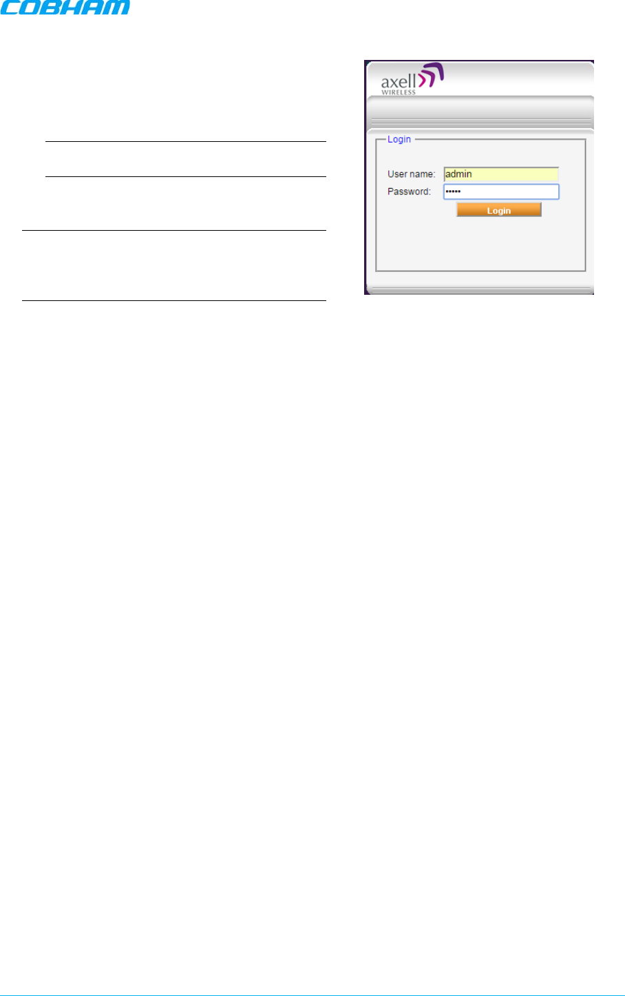
The Booster login dialog appears.
• Enter the authentication information:
Default User Name : admin
Default Password : admin.
NOTE: Both are case sensitive and must be
entered with lower case letters.
• Click Login. The application main
window appears.
NOTE: Quickly review the following section
describing the application window and then
proceed to configure the signal levels according
to section 5.3.
Figure
5-5. Login
D-MBR 3707-3708 PS NFPA CLASS B SIGNAL BOOSTER
PRODUCT DESCRIPTION AND USER’S MANUAL
www.cobham.com/wireless Cobham Wireless – Coverage Date: 6-Set-15
Page | 38 Doc. No. 00060CDUM Rev. 1.0
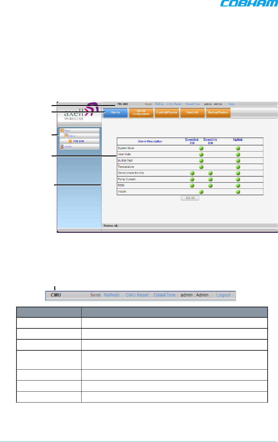
5.2.2 Navigating the Web GUI Application
This section describes how to navigate the Web Management application. The GUI interface provides
the following items:
• Operation options – always available in the header
• Menu selection left pane – provides three types of menu options
• Menu Tabs – sets of tabs corresponding to the selected left pane menu options
• Work area – corresponds to selected tab
Figure 5-6. Main Window
5.2.2.1 Operation Items
The operation options are always displayed in the window header.
Item Description
CMU/band/ Users Shows the currently selected menu item.
Send Uploads configuration changes to the Booster.
Refresh Refreshes the current screen and displayed data
CMU Reset Click to reset the Web Access application, in case of failure or
display issues
Date and Time Access Booster Date and Time settings.
User Currently logged in authentication level and user.
Logout Click to logout current user.
Menu selection
Pane related to
selected tab
Tabs related to
selected menu item
Operation buttons
Pane related to
selected tree item
Selected menu item
D-MBR 3707-3708 PS NFPA CLASS B SIGNAL BOOSTER
PRODUCT DESCRIPTION AND USER’S MANUAL
Cobham Wireless – Coverage Date: 6-Set-15 www.cobham.com/wireless
Doc. No. 00060CDUM Rev. 1.0 Page | 39
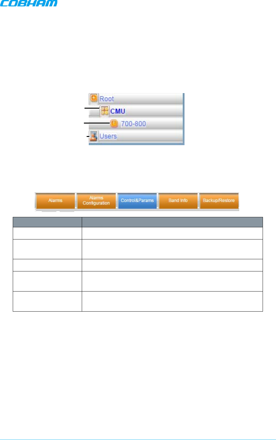
5.2.2.2 Left Pane Menu Options
The left pane contains three menu items, where clicking each item invokes dedication tabs and
options:
• CMU – communication, monitoring and administrative options.
• 700-800 – band-level RF configuration, management and monitoring options
• Users – user management tools, including
Password Change.
Figure 5-7. Menu Item
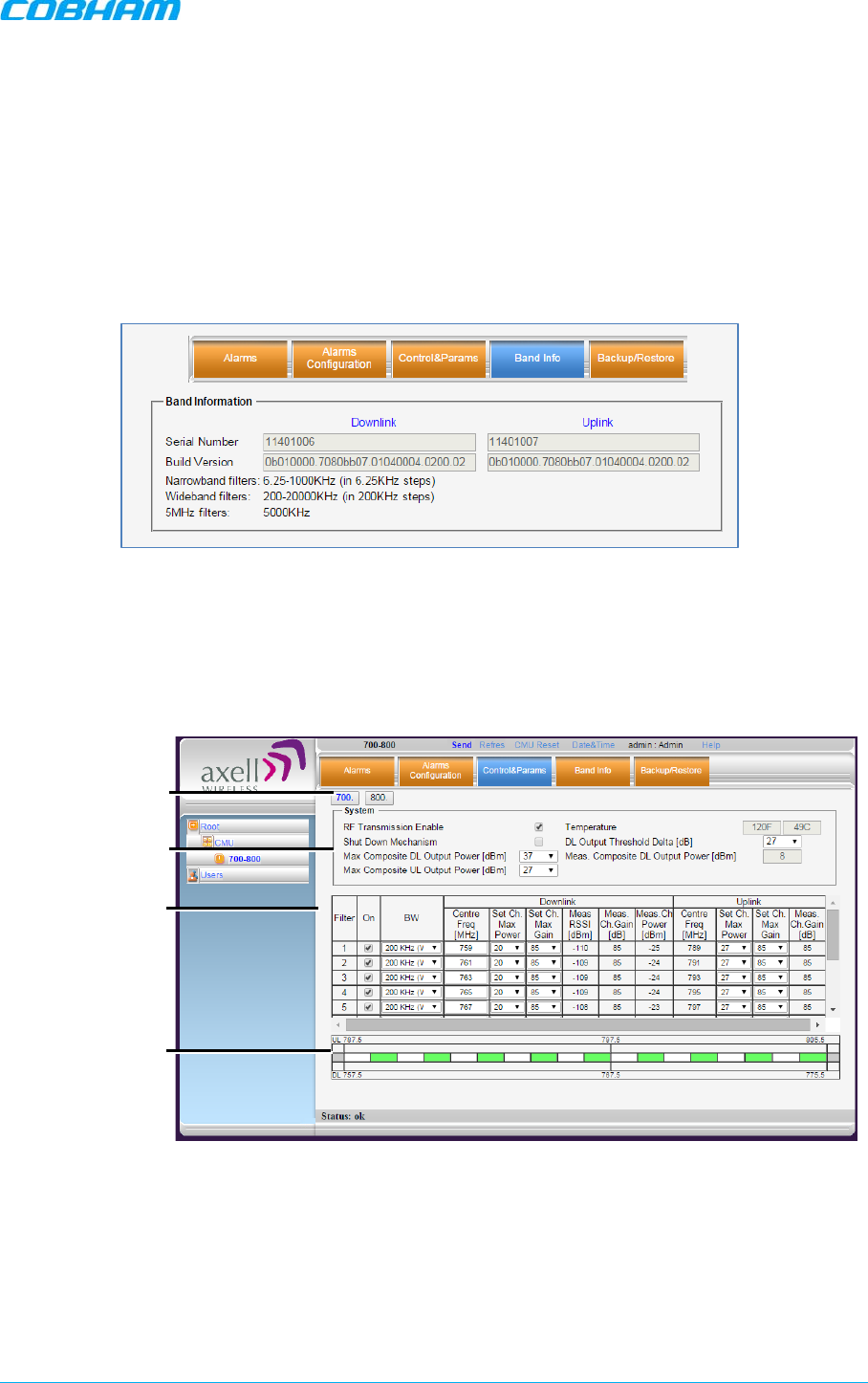
5.2.2.3 700-800 Menu Tabs
This section describes the tabs available when
700-800
is selected in the left pane.
Item Band Specific Description
Alarms Common alarms pane for both bands. See section 7.4.
Alarms Configuration
Viewing and modifying default alarm levels (critical, major,
minor), major). See section 7.5.
Control & Params RF configuration options for each band. See section 5.3.
Band Info Band specific information, including filter width, etc. See section
6.2.2
Backup and Restore Used to backup and manage band-level configuration files. See
section 6.3.
User management
and password change
Communication, monitoring
and administrative options
RF configuration options
D-MBR 3707-3708 PS NFPA CLASS B SIGNAL BOOSTER
PRODUCT DESCRIPTION AND USER’S MANUAL
www.cobham.com/wireless Cobham Wireless – Coverage Date: 6-Set-15
Page | 40 Doc. No. 00060CDUM Rev. 1.0
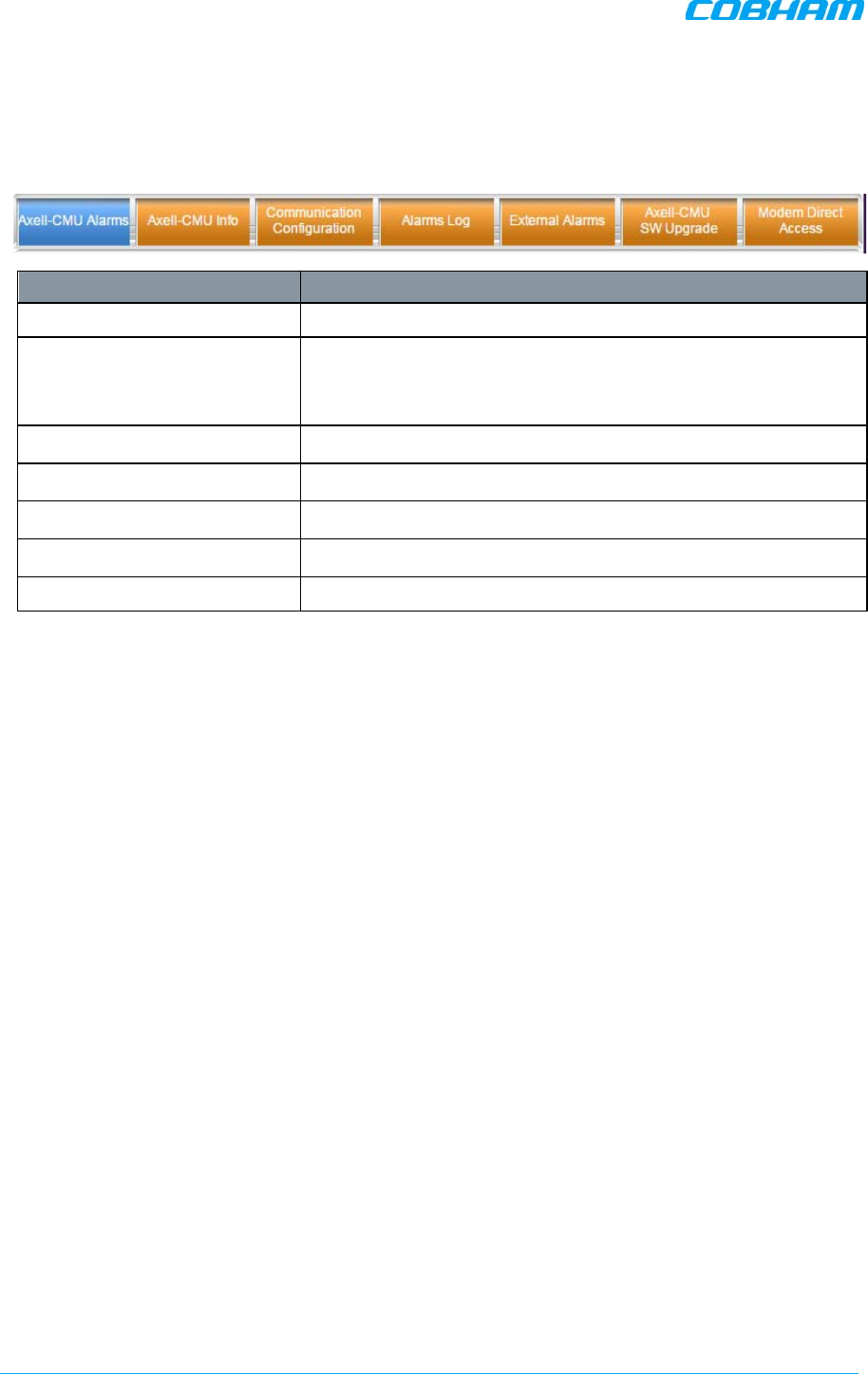
5.2.2.4 CMU Pane and Tabs
This section describes the tabs available when the
CMU item
is selected in the left pane.
Item Description / Values
Axell-CMU Alarms Shows any external alarms that were generated.
CMU Info Shows Booster level information such as SW and HW versions
and identification number. In addition, enables setting minimum
alarm levels (see 6.2.1).
Communication Configuration Used to set IP Address and SNMP parameters (see 5.6)
Alarms Log Booster level log of past and current alarms (see 7.2).
External Alarms External alarm configuration options. (see 5.5)
Axell-CMU SW Upgrade Options for Booster level software upgrade (see 6.4)
Modem Direct Access N/A
D-MBR 3707-3708 PS NFPA CLASS B SIGNAL BOOSTER
PRODUCT DESCRIPTION AND USER’S MANUAL
Cobham Wireless – Coverage Date: 6-Set-15 www.cobham.com/wireless
Doc. No. 00060CDUM Rev. 1.0 Page | 41
5.3 RF Parameters and Channel Configuration
Define up to 12 sub-bands with dedicated parameters for the 700 MHz and 800 MHz band according
to the instructions in this section. The defined filters are
graphically
displayed in the lower part of the
screen.
To configure the signal level and channels
1. In the left pane, click the 700-800 item.
2. View the valid filter definition options by clicking the Band Info tab.
Figure 5-8. Available Filters Options
3. To define the filters:
• Click the Control&Params tab.
• Click the button corresponding to the required band: 700 or 800.
Figure 5-9. Sub-band Allocation Configuration
The displayed pane is relevant to the selected band. It is divided into three areas:
o System – overall parameters for the
selected service.
o Sub-band (filter) definitions area.
o Graphical view of defined sub-bands.
Global RF
parameters
Define up to
12 filters
Graphical view of
defined filters
Choose band
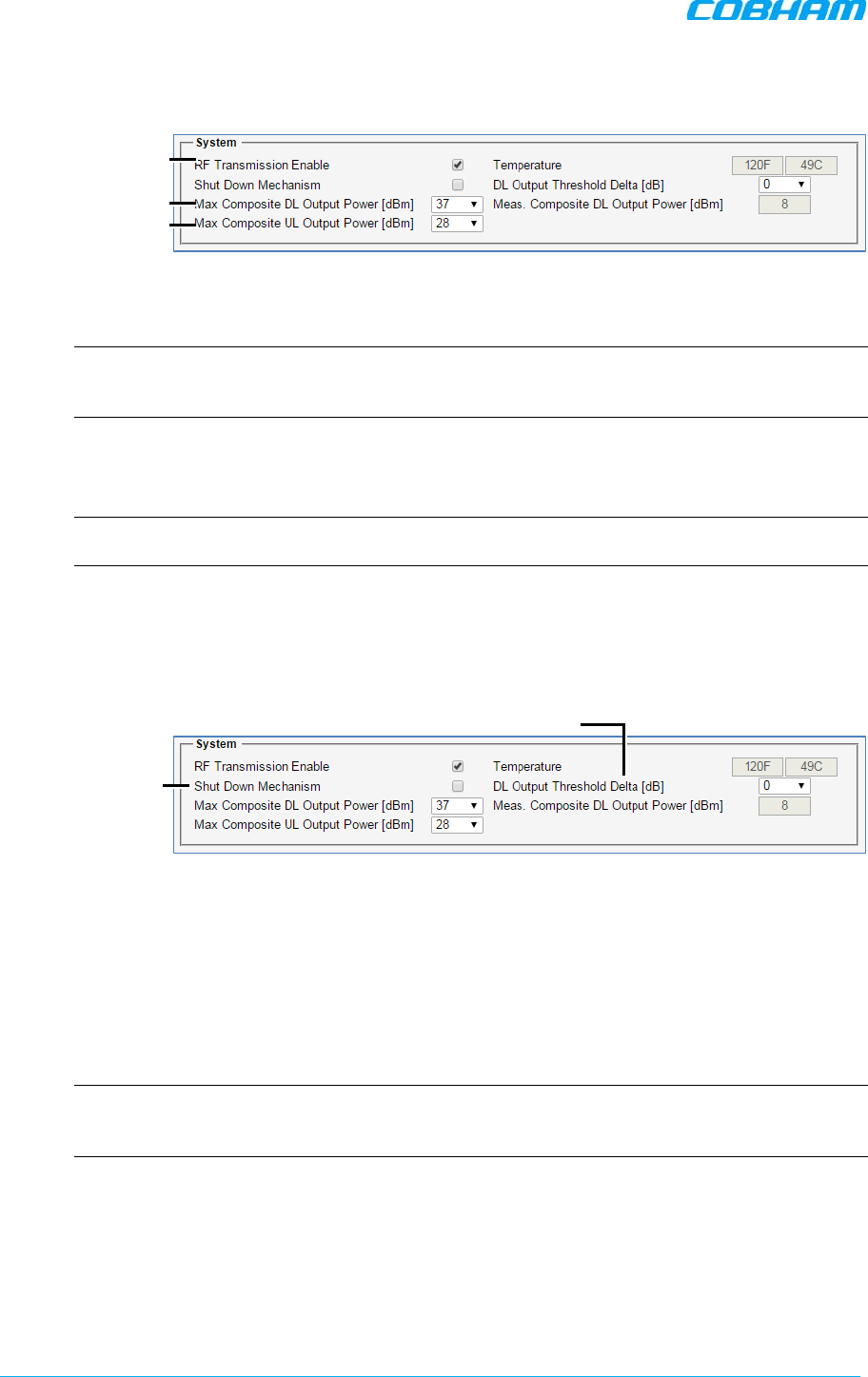
D-MBR 3707-3708 PS NFPA CLASS B SIGNAL BOOSTER
PRODUCT DESCRIPTION AND USER’S MANUAL
www.cobham.com/wireless Cobham Wireless – Coverage Date: 6-Set-15
Page | 42 Doc. No. 00060CDUM Rev. 1.0
4. Configure the general System parameters as follows:
Figure 5-10. Control and Params Tab – Required System Parameters
• Verify RF Transmission Enable is checked (RF transmission ON).
NOTE: Under certain conditions related to the Shut Down mechanism, the RF transmission
can be disabled (unchecked) by the system. The Shut Down mechanism is described in the
next step - Optional System parameters).
• Set Max Composite DL Output Power – set according to your site requirements
and click Send. The
Measured
Composite DL Output Power is displayed in the
adjacent field.
NOTE: If the composite output power exceeds the defined value, the Smart-ALC feature
begins working (refer to section 1.4 for more information on SALC).
• Set Max Composite UL Output Power – set according to your site requirements
and click Send.
5. You may modify the following System parameters – Shut Down Mechanism (disabled by default)
and DL Output Threshold Delta (set to ‘0’ be default):
Figure 5-11. Control and Params Tab – Optional System Parameters
• Shut Down Mechanism – if enabled, the system automatically disables RF
transmission if an excessively high input power (from the BTS side) is detected for a
specific period of time.
In that case, two operations are performed by the system:
o RF Transmission Parameter is unchecked (transmission is OFF)
o System Mute alarm (Alarms tab) is generated (RED).
NOTE: If the high input power issue is resolved, then it is necessary to enable RF
transmission by check-marking the RF Transmission Enable parameter. In addition, reset
the System Mute alarm (click Ack).
• DL Output Threshold Delta (dB) - delta from DL Output Power, below which the
alarm 'Donor power is too low' is activated.
Set DL value
Enabled
Set UL value
Disabled by
default
‘0’ by default
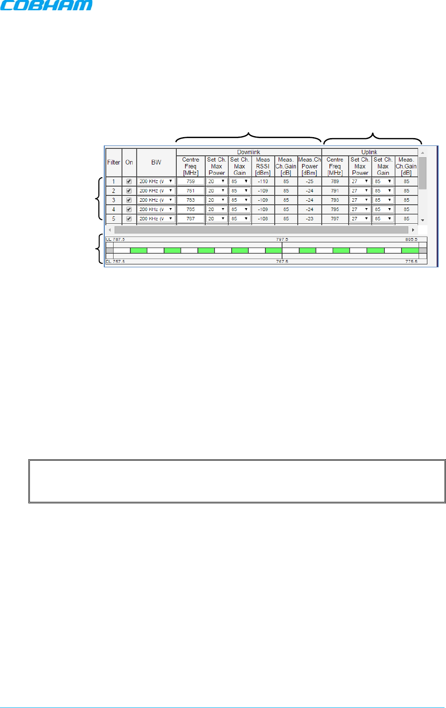
D-MBR 3707-3708 PS NFPA CLASS B SIGNAL BOOSTER
PRODUCT DESCRIPTION AND USER’S MANUAL
Cobham Wireless – Coverage Date: 6-Set-15 www.cobham.com/wireless
Doc. No. 00060CDUM Rev. 1.0 Page | 43
6. Enable the filters (up to 12 filters) and set the bandwidth as follows:
• Checkmark to ON each filter row. The corresponding options will be available.
• Select the BW (bandwidth) – the valid bandwidths are listed in the Band Info tab.
Figure 5-12. Control and Params Tab – Enabling and Configuring Filters
7. Set the DL parameters for the selected filter:
• DL Centre Freq - the resulting bandwidth will automatically be graphically displayed
and the corresponding Uplink Center frequency will automatically be allocated.
• Max Ch Max Power – set to maximum level by default. Modify as needed.
You may want to click Send after each filter definition and view the measured Channel
Power and the Composite Output Power (in the System are at the top of the screen).
• Max Ch Max Gain – set to maximum by default. Modify according to the
measured/calculated input power and isolation measurements.
Recommended Maximum Gain setting is approximately 16 dB less than the isolation between
the service and donor antennas.
More information on Downlink sub-band parameters
o DL Measured RSSI - measured DL signal.
o DL Measured Ch. Gain - measured DL Gain (dB) for the selected sub-band.
o DL Measured Ch. Power - measured Power (dBm) for the selected sub-band.
8. Set the UL parameters for the selected filter:
(The uplink channels and their values are automatically allocated according to the downlink
channel definitions.)
• Set Max Ch Max Power – by default, the power is set to maximum level. Modify as
needed.
You may want to click Send after each filter definition and view the measured Channel
Power and the Composite Output Power (in the System are at the top of the screen).
• Set Max Ch Max Gain - change the default value (maximum) according to the
measured/calculated input power and isolation measurements.
Recommended Maximum Gain setting is approximately 16 dB less than the isolation between
the service and donor antennas.
9. Click Send (top window area option).
Downlink Channels
Uplink Channels
Enable and
configure filters
Graphical display of
configured filters
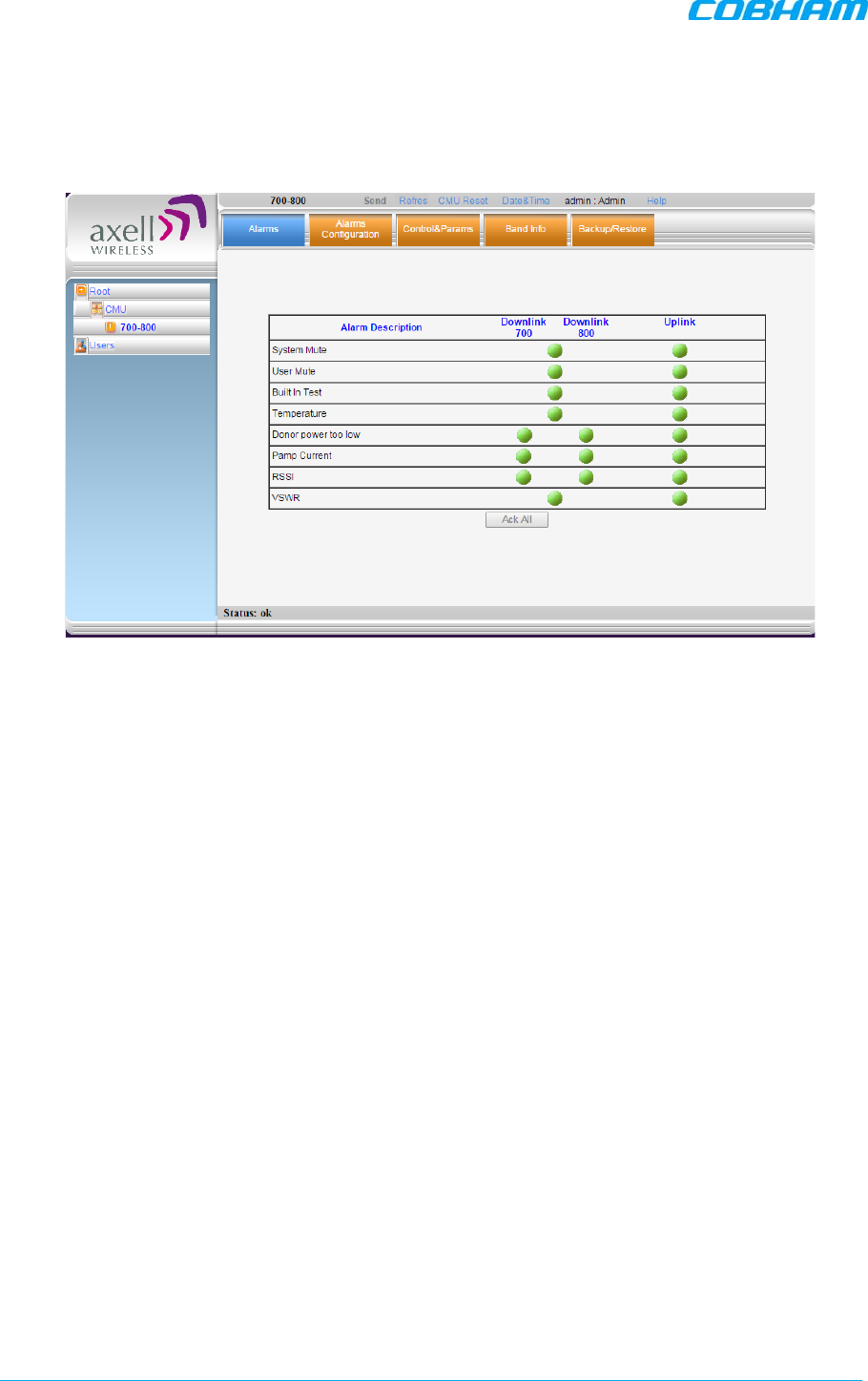
D-MBR 3707-3708 PS NFPA CLASS B SIGNAL BOOSTER
PRODUCT DESCRIPTION AND USER’S MANUAL
www.cobham.com/wireless Cobham Wireless – Coverage Date: 6-Set-15
Page | 44 Doc. No. 00060CDUM Rev. 1.0
10. After the channels have been configured and the required coverage is attained for the location,
verify that no Alarms are generated:
• Click the Alarms tab
• Verify that all the indicators are GREEN in the Alarms tab
Figure 5-13. Alarms Dialog
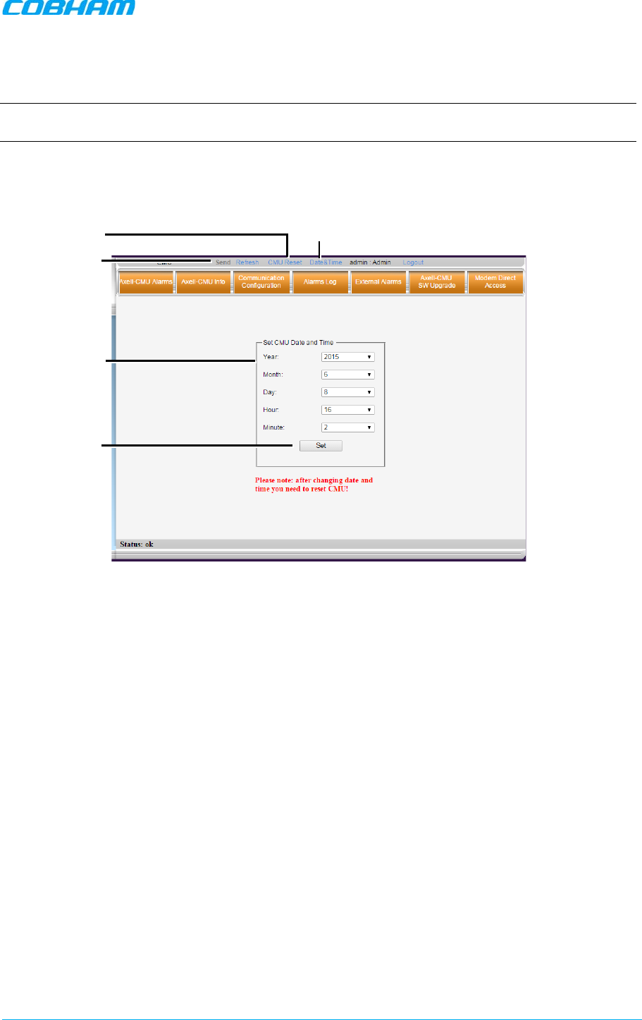
D-MBR 3707-3708 PS NFPA CLASS B SIGNAL BOOSTER
PRODUCT DESCRIPTION AND USER’S MANUAL
Cobham Wireless – Coverage Date: 6-Set-15 www.cobham.com/wireless
Doc. No. 00060CDUM Rev. 1.0 Page | 45
5.4 Date and Time Settings
NOTE: It is important to set the correct date and time on the unit since this provides the timestamp
for each logged event and alarm. This operation requires resetting the Booster.
To set the Boosters date and time
1. Click on Date & Time in the Operations Items bar ( 5.2.2.1). The following dialog appears.
Figure 5-14. Date & Time Settings Dialog
2. Set ALL the date and time parameters.
3. Click on Set in the dialog and then Send at the top of the screen
4. Click the CMU Reset button in the Operations Bar.
Date & Time item
1. Define ALL
3. Click
Send
(after clicking
Set)
2. Click
Set
4. Click Reset
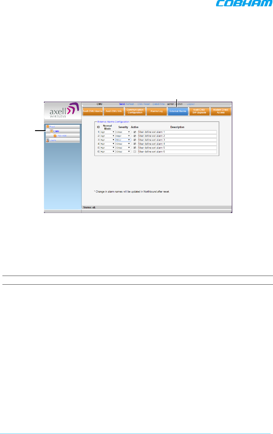
D-MBR 3707-3708 PS NFPA CLASS B SIGNAL BOOSTER
PRODUCT DESCRIPTION AND USER’S MANUAL
www.cobham.com/wireless Cobham Wireless – Coverage Date: 6-Set-15
Page | 46 Doc. No. 00060CDUM Rev. 1.0
5.5 External Alarms Configuration
It is required to configure an external alarms that have been connected to the Booster (either from
the UPS / Battery Charger or from another external source, these must.
To configure external alarms
1. In the left pane, click on the CMU option and select the External Alarms tab. The following
dialog appears.
Figure 5-15. External Alarm Configuration Dialog
2. For each connected alarm:
• Check the “Active” checkbox.
• Set the alarm Normal Mode as High or Low.
• In the Description field, assign the alarm an identifiable name (e.g. Door open).
The
description will be updated after Booster reset.
NOTE: Triggered external alarms are displayed in the Axell-CMU-Alarms tab.
Click CMU
External Alarms tab
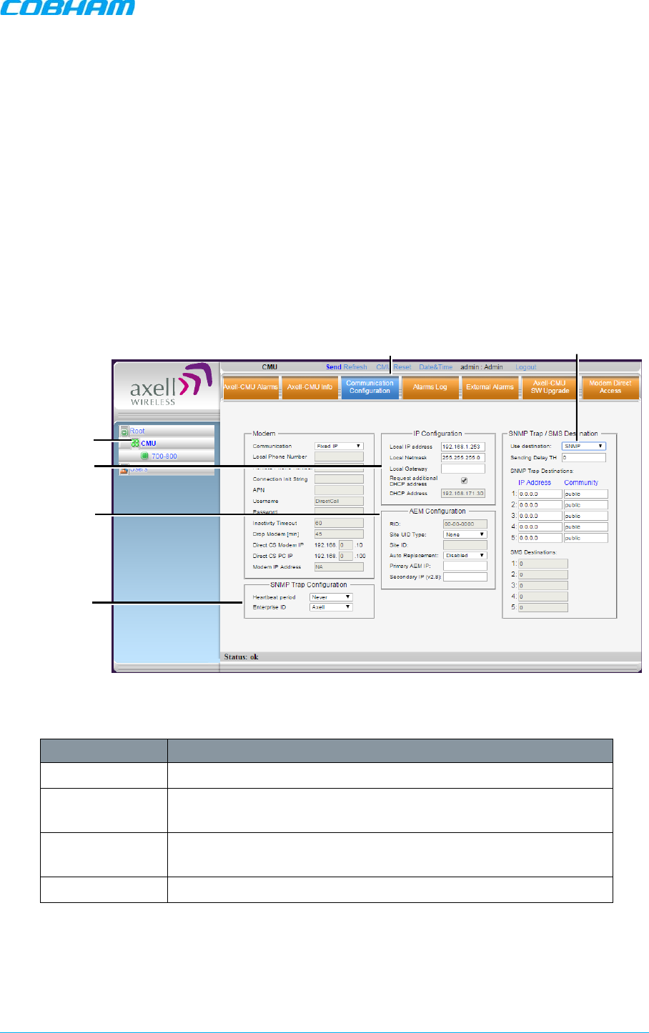
D-MBR 3707-3708 PS NFPA CLASS B SIGNAL BOOSTER
PRODUCT DESCRIPTION AND USER’S MANUAL
Cobham Wireless – Coverage Date: 6-Set-15 www.cobham.com/wireless
Doc. No. 00060CDUM Rev. 1.0 Page | 47
5.6 IP Address and SNMP Notifications
This section describes how to define the following parameters:
• Booster’s IP Address and SNMP notifications management
• AEM management support
• Auto-replace
All options are defined via the Communication Configuration Screen
To configure the IP Address and SNMP Notifications
1. Click on CMU in the left pane and select the Communication Configuration tab. The
following screen appears.
Figure 5-16. Communication Configuration Dialog
The following areas are relevant to this Booster installation.
Area Description
IP Configuration Used to define Static IP Address and DHCP Address.
AEM
Configuration Used to define auto-replacement options for AEM management.
SNMP Trap
options This includes enabling SNMP Trap options and defining the relevant
parameters.
AEM Used to configure the repeater for AEM support
SNMP notifications
Click CMU
Click
Communication
AEM Config
SNMP Trap
Config
IP Address
config
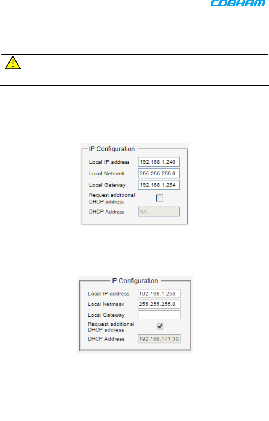
D-MBR 3707-3708 PS NFPA CLASS B SIGNAL BOOSTER
PRODUCT DESCRIPTION AND USER’S MANUAL
www.cobham.com/wireless Cobham Wireless – Coverage Date: 6-Set-15
Page | 48 Doc. No. 00060CDUM Rev. 1.0
5.6.1 Configuring the IP Address
The Booster supports both Static and DHCP addresses. A unique technology enables applying both
types to the
same
Ethernet port. Both addresses may enable local and remote management.
ATTENTION!! The Local IP Address is a static address assigned by the user to the system.
The default Static IP address is 192.168.1.253. It is highly recommended to preserve this setup.
In case of a change, make sure you record the newly assign IP.
To configure the Booster IP address
1. Click the left pane CMU item and select the Communication tab.
2. To assign the unit a Local IP Address:
In the IP Configuration area, assign the unit the Local IP address, Netmask and Gateway
parameters provided by your system administrator.
Figure 5-17. Network Settings
3. To configure the booster to operate with a DHCP Server:
• Checkmark Request Additional DHCP Address.
• The assigned address can be seen in the DHCP Address field.
Figure 5-18. Network Settings
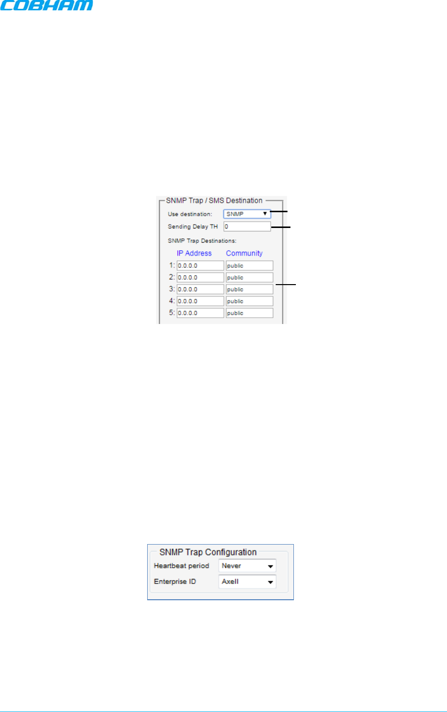
D-MBR 3707-3708 PS NFPA CLASS B SIGNAL BOOSTER
PRODUCT DESCRIPTION AND USER’S MANUAL
Cobham Wireless – Coverage Date: 6-Set-15 www.cobham.com/wireless
Doc. No. 00060CDUM Rev. 1.0 Page | 49
5.6.2 SNMP Trap Configuration
The Booster can be configured provide fault notification by sending traps to up to five defined IP
addresses each time a fault is triggered. The traps are sent at the defined heartbeat frequency and
can be sent with a Sending Delay.
To set SNMP Trap Destination parameters
1. Click the left pane CMU item and select the Communication tab.
2. In the SNMP Trap / SMS Destination area, set the Use Destination field to the SNMP
option
3. In the Use Destination field, select the SNMP option
4. For each destination:
• Define the IP Address (where the IP addresses should be in the same subnet as the
booster).
• Define the Community names (default = public) of the computers to which traps will
be sent.
5. Sending Delay TH (Optional) - by default, there is no sending delay (‘0’ value) and the alarm
is continuously sent as long as the fault exists.
By configuring the Sending delay TH, the same alarm is sent again, only if the fault persists for
the configured (minutes) time period.
6. In the SNMP Trap Configuration area, in the Heartbeat Period field, define the frequency
(in minutes) at which traps will be sent.
It is recommended to maintain the Enterprise ID value
as Axell.
7. In the window Operations Bar, click Send.
Select
SNMP
Define up to five SNMP
destination addresses
Optional (in minutes)
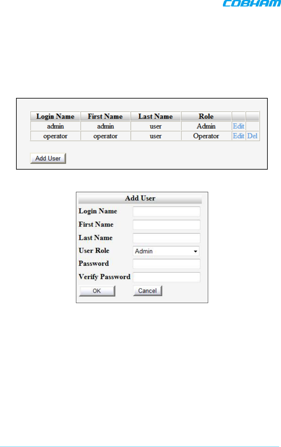
D-MBR 3707-3708 PS NFPA CLASS B SIGNAL BOOSTER
PRODUCT DESCRIPTION AND USER’S MANUAL
www.cobham.com/wireless Cobham Wireless – Coverage Date: 6-Set-15
Page | 50 Doc. No. 00060CDUM Rev. 1.0
5.7 Changing Password
For security, it is recommended to change the password of the Administrator.
To change the administrator password
1. From the left pane, select Users. The list of users is displayed in the User's Pane.
2. In the admin row, click Edit and modify the relevant information – specifically the password.
Figure 5-19. Add User
3. Enter the Password and in Verify Password enter the password again for verification.
4. Click OK.
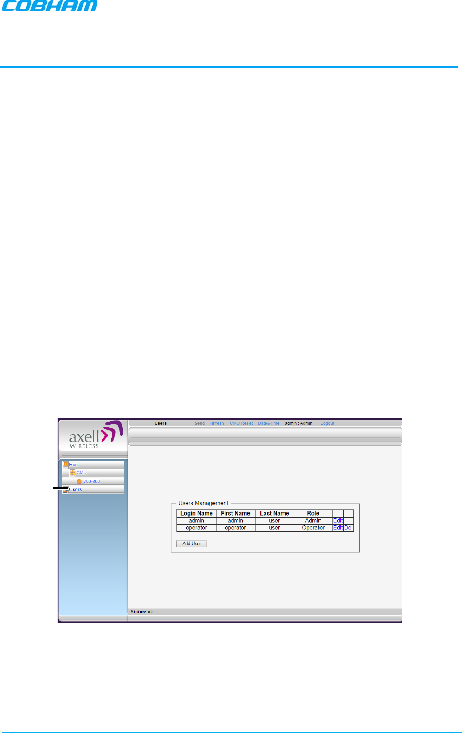
D-MBR 3707-3708 PS NFPA CLASS B SIGNAL BOOSTER
PRODUCT DESCRIPTION AND USER’S MANUAL
Cobham Wireless – Coverage Date: 6-Set-15 www.cobham.com/wireless
Doc. No. 00060CDUM Rev. 1.0 Page | 51
6 ADMINISTRATIVE OPERATIONS
The following administrative operations are described in this section:
• User Management – defining and changing users and passwords.
• Viewing the Booster information such as software and hardware versions, serial number.
• Software upgrade
6.1 User Management
This section describes how to perform the user management operations. By default,
two
users
belonging to one of three authentication levels are defined on the Booster. You may add new users,
modify or delete existing users.
6.1.1 User Levels
Two user levels are available:
• Admin – has access to all administration and configuration options, including user management.
(Default Password admin and default User Name admin.)
• Operator – has access to all configuration options
except
for the Users list or the Loaders screen.
6.1.2 Viewing the List of Defined Users
To display the User Administration pane
From the left pane, select Users. The list of users is displayed in the Configuration Pane according to
the identifying information and authentication level (Role).
Figure 6-1. User Administration Pane
Click Users
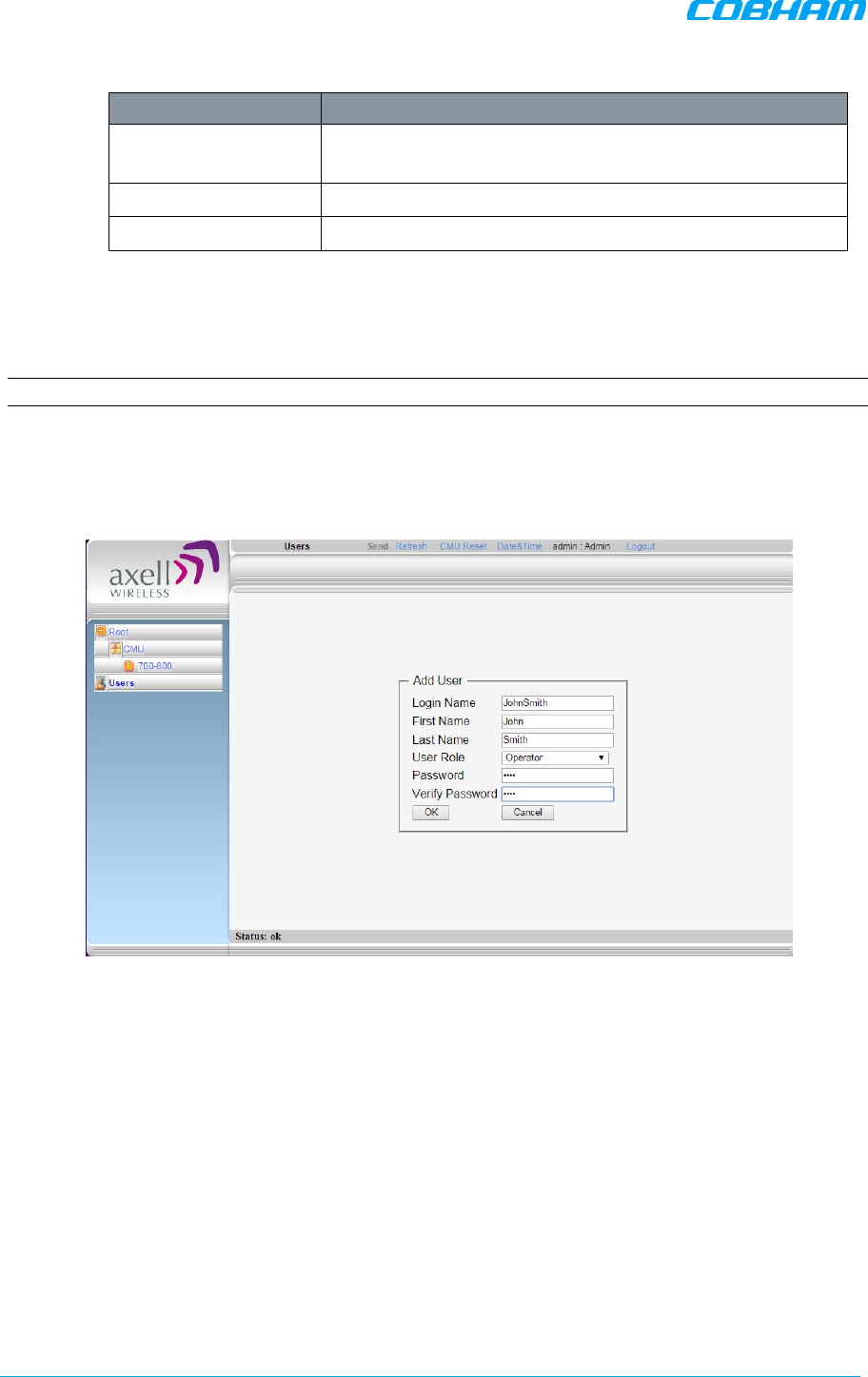
D-MBR 3707-3708 PS NFPA CLASS B SIGNAL BOOSTER
PRODUCT DESCRIPTION AND USER’S MANUAL
www.cobham.com/wireless Cobham Wireless – Coverage Date: 6-Set-15
Page | 52 Doc. No. 00060CDUM Rev. 1.0
The following table provides a description of the Users dialog options.
Option Description
Add User (button) Adds a new user with to user
defined access level and
password.
Del(ete) Deletes a selected user from the list.
Edit Enables changing the definitions of an existing user.
6.1.3 Adding Users
NOTE: User name and password entries are case sensitive.
To add a user
1. From the left pane, select Users. The list of users is displayed in the User's Pane.
2. From the User's Pane, click Add User. The Add User dialog box is displayed.
Figure 6-2. Add User
3. Enter the Login Name – name used by user to login.
4. Type the user's First Name and Last Name – used to identify the user.
5. Select the User Role – access level. This defines the operations that the user will be able to
perform.
6. Enter the Password and in Verify Password enter the password again for verification.
7. Click OK.
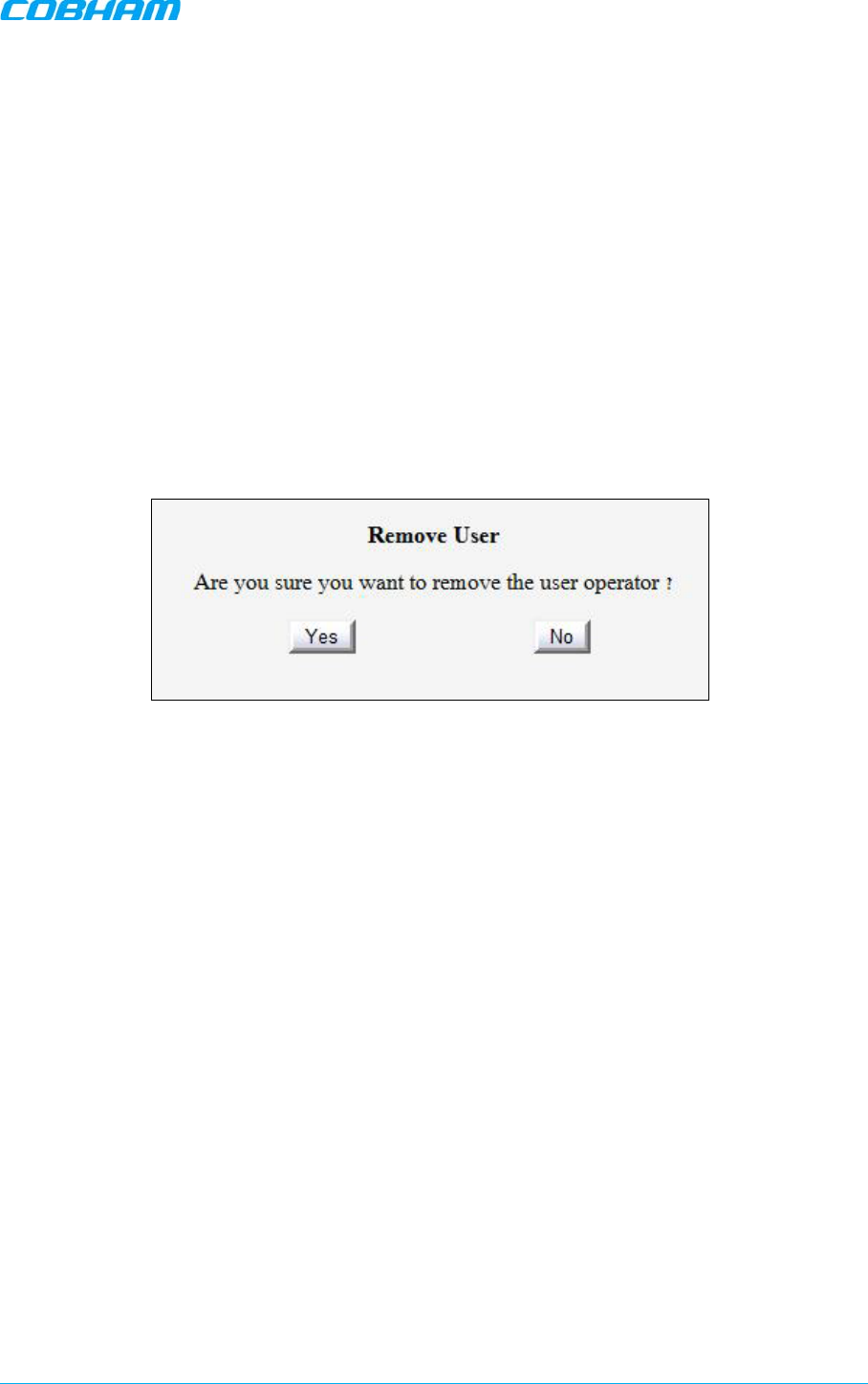
D-MBR 3707-3708 PS NFPA CLASS B SIGNAL BOOSTER
PRODUCT DESCRIPTION AND USER’S MANUAL
Cobham Wireless – Coverage Date: 6-Set-15 www.cobham.com/wireless
Doc. No. 00060CDUM Rev. 1.0 Page | 53
6.1.4 Editing a User
To modify user definitions
1. From the left pane, select Users. The list of users is displayed in the User's Pane.
2. Select the User to be edited in the list.
3. Click Edit. The user definitions dialog appears.
4. Make the required changes and click OK.
6.1.5 Deleting a User
To delete a user
1. From the left pane, select Users. The list of users is displayed in the User's Pane.
2. Select the User to be deleted in the list.
3. From the User's Pane, click Del. An authorization message dialog box is displayed.
Figure 6-3. Remove User
4. Click Yes. The User’s name is removed from the list.
6.2 Viewing General Information
The Web GUI provides Booster level information (via the CMU Info tab) and band level information
(via the Band Info tab).
6.2.1 Viewing Booster Level Information
Use the CMU Info screen to view the hardware and software versions of the
Booster and to assign the Booster a recognizable name.
To access the Band Information window
1. In the left pane, select CMU and click the CMU Info tab.
2. You may define the following parameters:
• Log Level - sets the minimum fault level that is logged.
• CMU name – identifiable user-defined name.
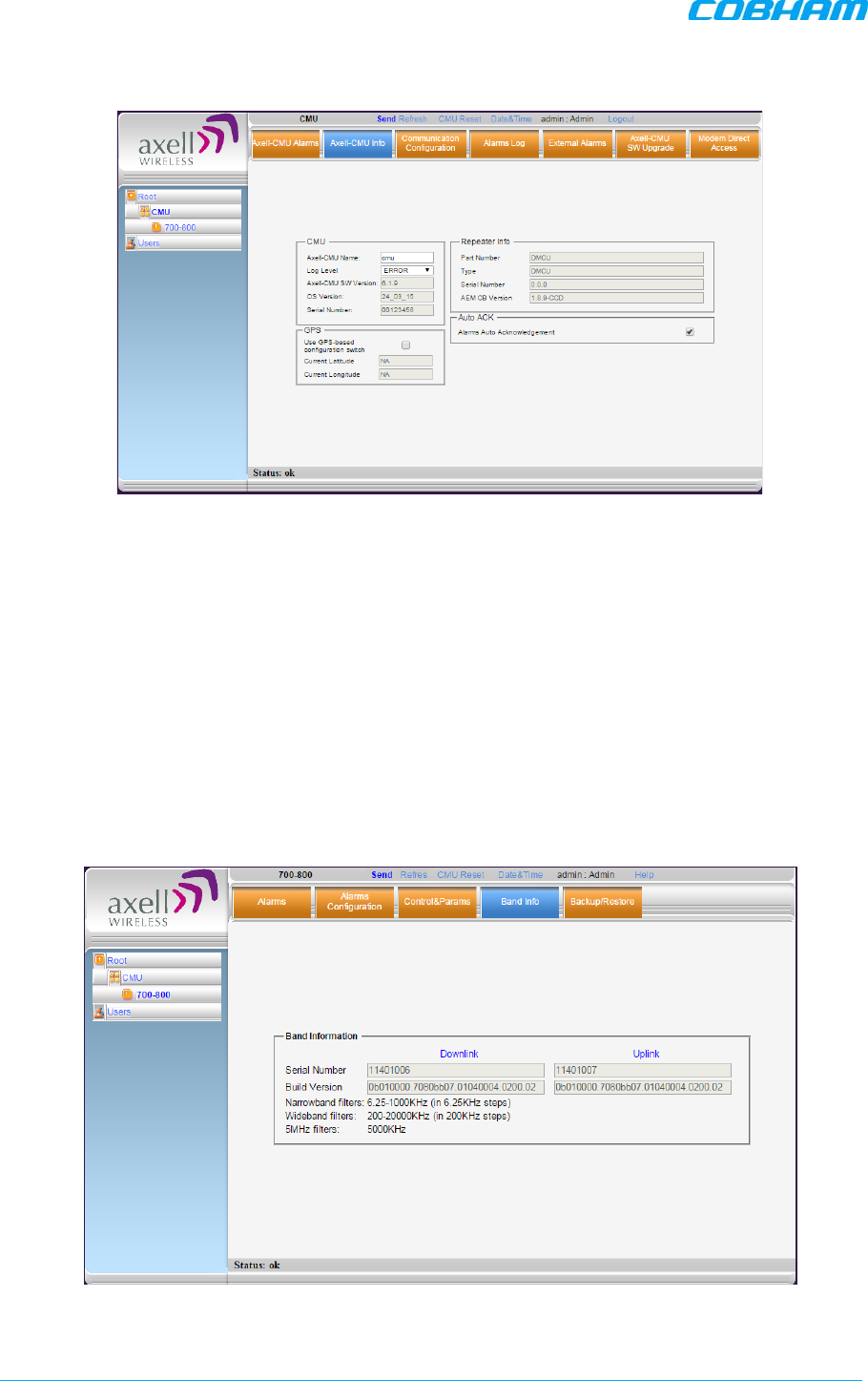
D-MBR 3707-3708 PS NFPA CLASS B SIGNAL BOOSTER
PRODUCT DESCRIPTION AND USER’S MANUAL
www.cobham.com/wireless Cobham Wireless – Coverage Date: 6-Set-15
Page | 54 Doc. No. 00060CDUM Rev. 1.0
(Other fields provide version and identification information.)
Figure 6-4. CMU Level Info
6.2.2 Viewing Band Level Info
This Band Info tab displays general identification information such as build version, valid filter
definitions and more.
To access the Booster Information window
1. From the left pane, select the 700-800 item.
2. Select the Band Info tab. The relevant parameters are displayed. This includes:
• Build Version
• Filters types and relevant bandwidth – this information is relevant when defining the
RF parameters and sub-bands for each band.
Figure 6-5. Band Level Information
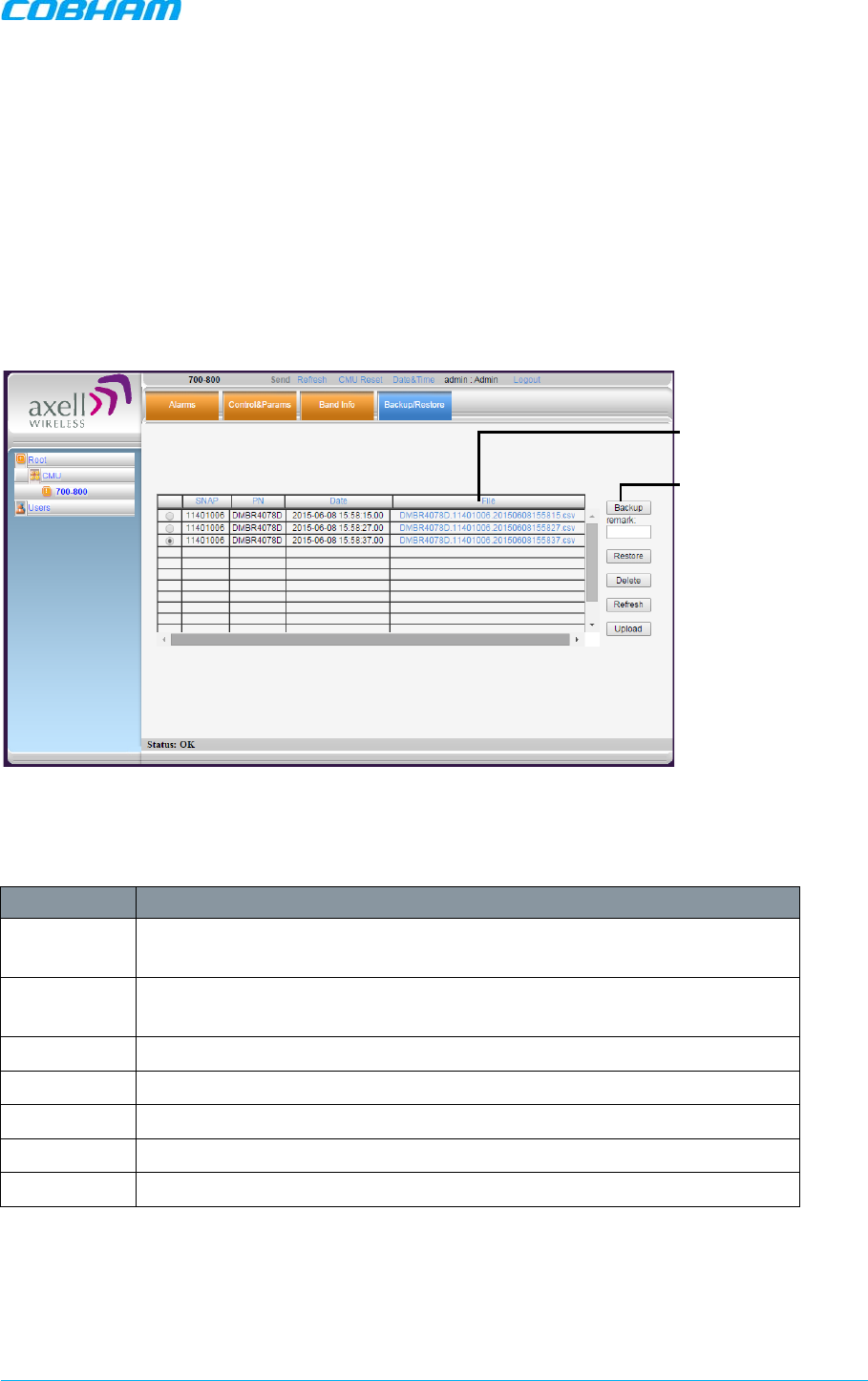
D-MBR 3707-3708 PS NFPA CLASS B SIGNAL BOOSTER
PRODUCT DESCRIPTION AND USER’S MANUAL
Cobham Wireless – Coverage Date: 6-Set-15 www.cobham.com/wireless
Doc. No. 00060CDUM Rev. 1.0 Page | 55
6.3 Band-Level Configuration Backup/Restore
The Web GUI management application enables the backup and restore of the band level
configuration options. A number of configuration files can be stored on the Booster for access and
restoring at any time. The procedures are performed via the Backup/Restore tab.
6.3.1 The Backup/Restore Tab
To access Backup/Restore tab
In the left pane, click the 700-800 item and click the Backup/Restore tab. The following screen
appears.
Figure 6-6. Backup and Restore
The file management buttons provide the following options:
Item Description
Backup Backup the currently running configuration file to a selected location. The
file will be added to the list.
Remark User defined name that will be assigned to the file saved using the Backup
file. (Instead of the system assigned name).
Restore Select and upload an existing band level configuration file.
Delete Deletes the
selected
file from the list.
Refresh Refreshes the displayed list of files.
Upload Enables uploading a configuration file from another location to the Booster.
File Click links to download files and save to another location.
Currently saved files
(click link to Save As)
Backup and restore
operation options
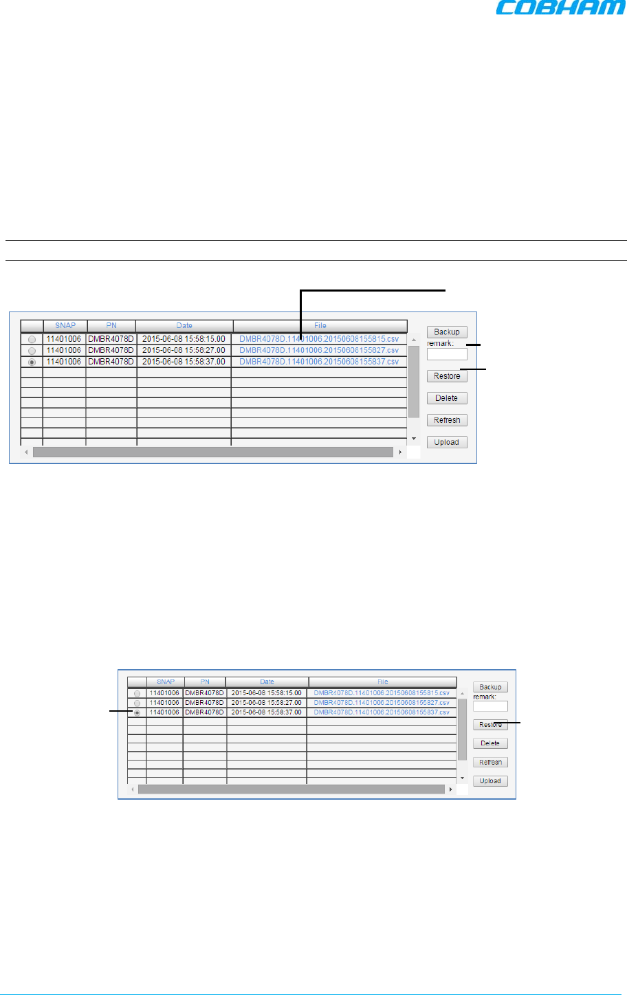
D-MBR 3707-3708 PS NFPA CLASS B SIGNAL BOOSTER
PRODUCT DESCRIPTION AND USER’S MANUAL
www.cobham.com/wireless Cobham Wireless – Coverage Date: 6-Set-15
Page | 56 Doc. No. 00060CDUM Rev. 1.0
6.3.2 Backup Band Configuration
To backup the current configuration
1. In the left pane, click the 700-800 item and then click the Backup/Restore tab.
2. To assign the configuration file a recognizable name, enter a name in the remark field.
Otherwise, the file will be assigned a name by the system.
3. Click the Backup button located on the right-hand side of the tab.
4. The file will be added to the table displayed in the Backup/Restore tab.
Note: The file name (under File) is a link that enables uploading the file to another location.
Figure 6-7. Backup Booster Info
6.3.3 Restoring Band Configuration
To restore previous configuration
1. In the left pane, click the 700-800 item and then click the Backup/Restore tab.
2. Select the required configuration file (enable corresponding radio button) from the available list
in the Backup/Restore tab.
3. Click the Restore button.
Figure 6-8. Restore Band Configuration
4. Click on the Control and Params tab and verify that the required configuration settings have
been restored.
1. Select
configuration file
(radio button)
2. Click Restore.
1. Assign tag
2. Click Backup
Currently saved files
(click link to Save As)
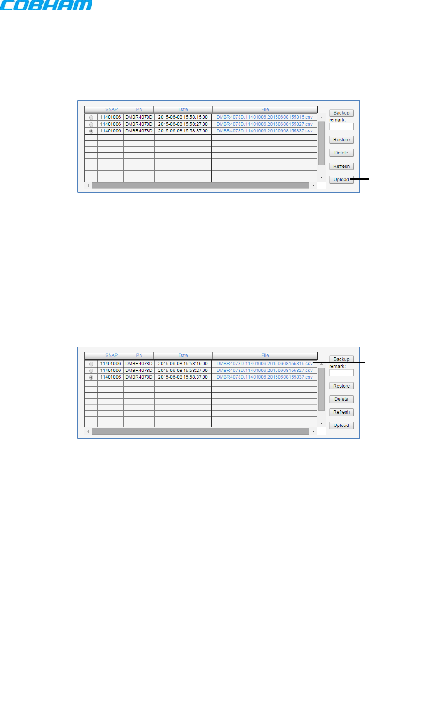
D-MBR 3707-3708 PS NFPA CLASS B SIGNAL BOOSTER
PRODUCT DESCRIPTION AND USER’S MANUAL
Cobham Wireless – Coverage Date: 6-Set-15 www.cobham.com/wireless
Doc. No. 00060CDUM Rev. 1.0 Page | 57
6.3.4 Uploading Band Configuration File
To upload configuration file to Booster
1. In the left pane, click the 700-800 item and then click the Backup/Restore tab.
Figure 6-9. Upload Configuration File
2. Click the Upload button.
3. Select the file from the Browse dialog and click Open.
4. The file will be listed in the Backup/Restore table.
6.3.5 Saving Configuration File to Computer
To save a configuration file from the list to a selected location
1. In the left pane, click the 700-800 item and then click the Backup/Restore tab.
Figure 6-10. Save File in a Different Location
2. Select file from list.
3. Click the link in the File column.
4. Select the location in the Browse dialog
Click Upload and
browse
Click desired link
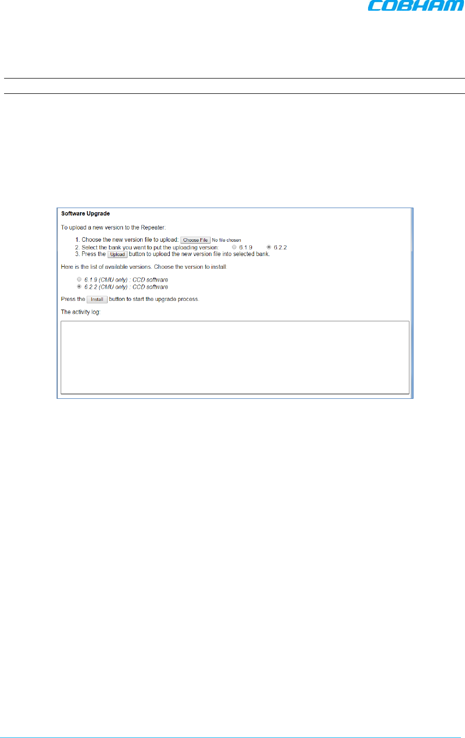
D-MBR 3707-3708 PS NFPA CLASS B SIGNAL BOOSTER
PRODUCT DESCRIPTION AND USER’S MANUAL
www.cobham.com/wireless Cobham Wireless – Coverage Date: 6-Set-15
Page | 58 Doc. No. 00060CDUM Rev. 1.0
6.4 CMU Software Upgrade
NOTE: This procedure is performed for every new management version.
The procedure described in this section is used to upgrade the Booster software. The CMU SW
upgrade procedure consists of loading the new software version and installing it in the CCD. The
CMU can store two versions on two separate data banks enabling restore to a previous version.
To Upgrade the CMU SW
1. In the left pane, click the CMU item and then click the CMU SW Upgrade tab. The following
screen appears (the Browse field will be empty).
Figure 6-11. CMU Upgrade
2. Choose and save the file onto the Booster:
• (1) Click Choose File to search for the location and choose the new software file. It
will be displayed adjacent to the Choose File button.
• (2) Select the bank where the file will be stored. (Before it is populated the bank will
be named ‘empty slot’. After it is populated, it will take on the name of the stored
software version). Any existing software file will be replaced.
• (3) Press Upload to save the file to the selected bank (slot). The available software
files to choose from will be listed.
3. Choose the required software file and click Install.
4. The Activity Log will indicate status and upgrade completion.
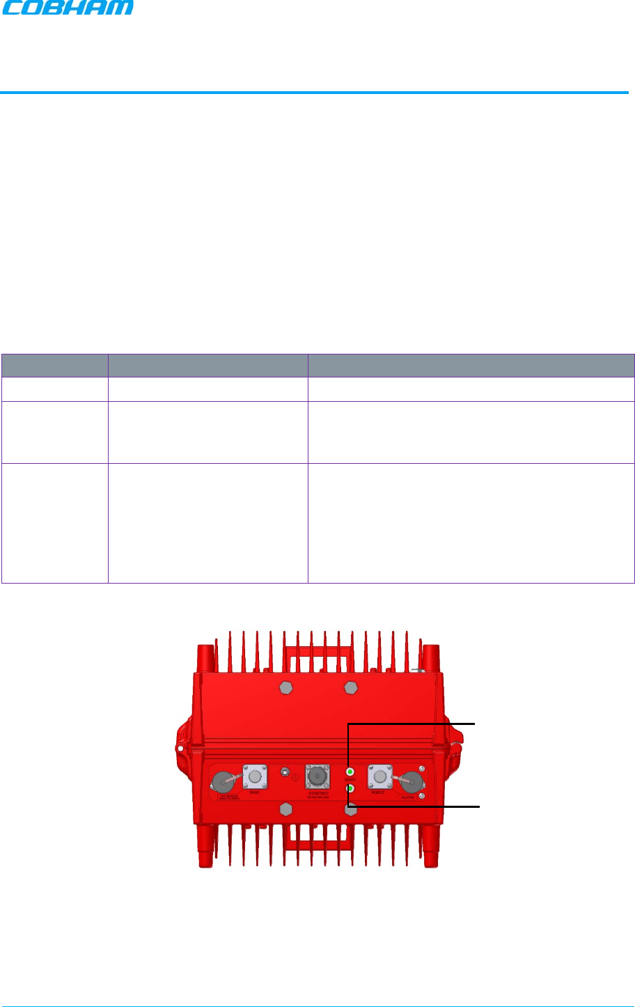
D-MBR 3707-3708 PS NFPA CLASS B SIGNAL BOOSTER
PRODUCT DESCRIPTION AND USER’S MANUAL
Cobham Wireless – Coverage Date: 6-Set-15 www.cobham.com/wireless
Doc. No. 00060CDUM Rev. 1.0 Page | 59
7 MONITORING AND TROUBLESHOOTING
The D-MBR Booster provides the following indications of Booster failure:
• LED: on Booster front panel
• Booster level Alarms Log – displays a log of past and current generated alarms on a Booster level
• Band level Alarms screen – displays currently active band-level alarms
The following sections provide a description of the troubleshooting procedures according to the
Booster LED indicators and the Web Alarms.
7.1 LED Troubleshooting
Two status LEDs are located on the Booster panel – one for the Uplink and one for the Downlink.
The LEDs provides the following information:
Color Description Corrective Action
Green Normal (UL or DL) operation -
Red Power failure (in UL or DL) Corrective action: Turn off the Booster (this action
causes a reset of the function), and turn it on
anew. If the fault resumes, replace the unit.
Blinking
Orange/red Mute - either user- or
system-initiated.
(System initiated mute may
be due to isolation problem
or temperature).
Check gain of the booster
, if gain is minimum,
then it is an isolation problem -
> improve
isolation.
Turn OFF the Booster (resets the function), and
turn it ON again. If the fault resumes, replace the
unit.
Figure 7-1. UL and DL Status LEDs located on Underside Panel
UL Status LEDs
DL Status LEDs
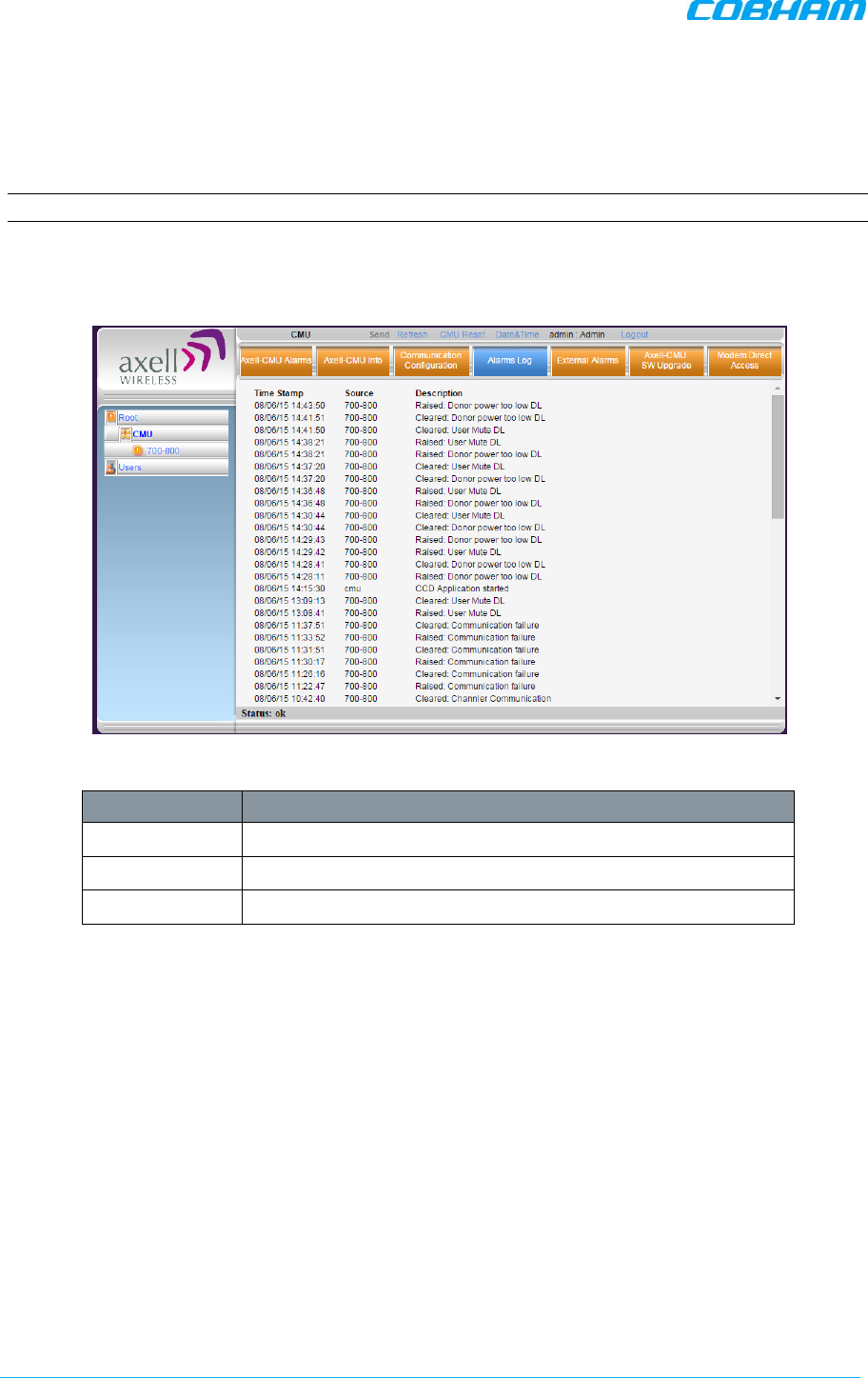
D-MBR 3707-3708 PS NFPA CLASS B SIGNAL BOOSTER
PRODUCT DESCRIPTION AND USER’S MANUAL
www.cobham.com/wireless Cobham Wireless – Coverage Date: 6-Set-15
Page | 60 Doc. No. 00060CDUM Rev. 1.0
7.2 Booster Level Alarms Log
The CMU maintains log files listing every alarm triggered in the Booster. These are displayed in the
Alarms Log screen. This screen provides an analysis tool to get information of any event that has
occurred, its originator, when, if they return, and their type.
NOTE: Time of occurrence of the events is set according to the Booster clock ( 5.4).
To view the CMU log screen:
Click on CMU in the left pane and select the Alarms Log tab. The following screen appears.
Figure 7-2. CMU Log Screen
Item Description
Time Stamp The date and time the alarm was created
Source ID of Network Element
Description Description of event that caused the alarm
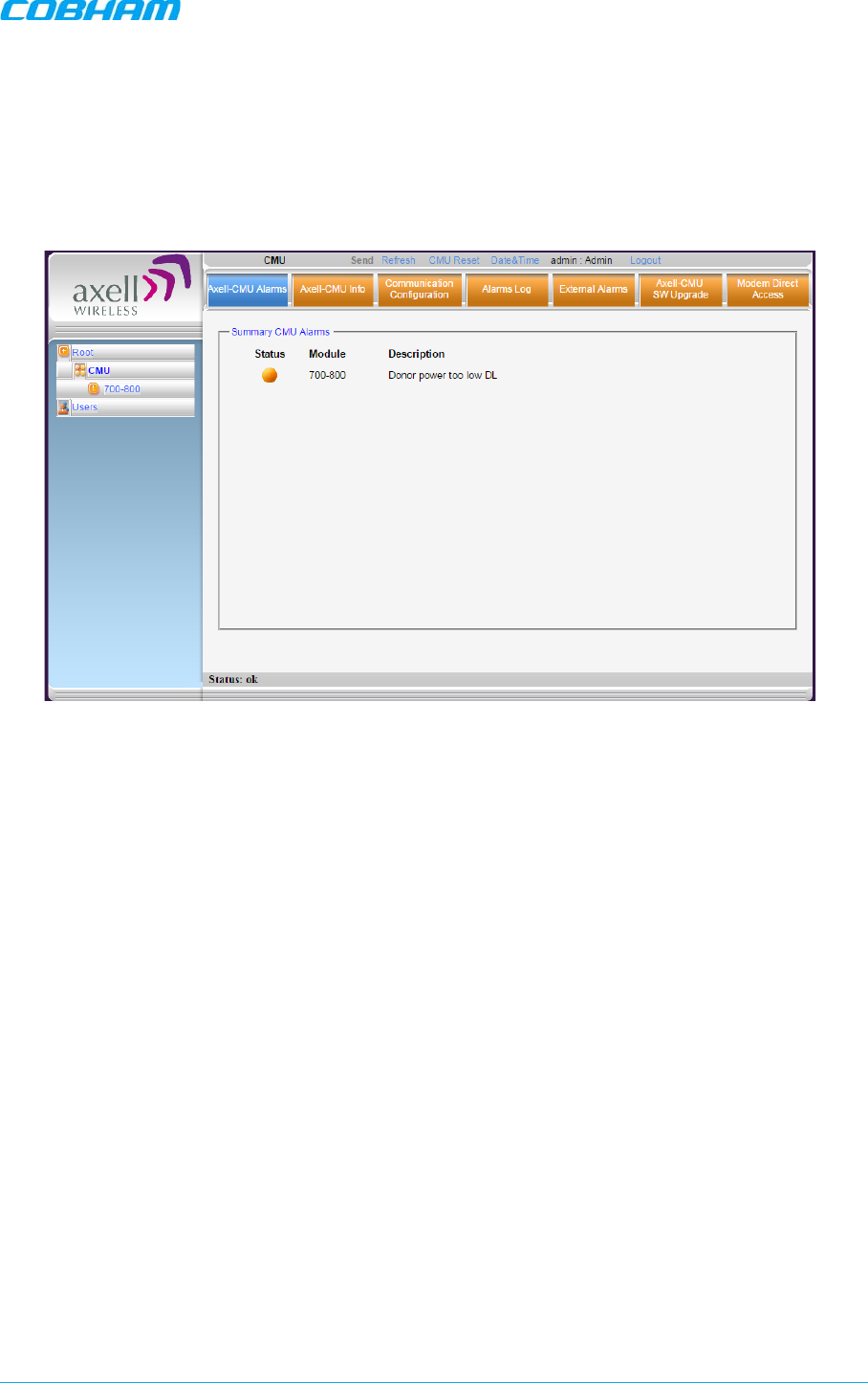
D-MBR 3707-3708 PS NFPA CLASS B SIGNAL BOOSTER
PRODUCT DESCRIPTION AND USER’S MANUAL
Cobham Wireless – Coverage Date: 6-Set-15 www.cobham.com/wireless
Doc. No. 00060CDUM Rev. 1.0 Page | 61
7.3 CMU Alarms
Click on CMU in the left pane and select the CMU Alarms tab. The following screen appears. The
screen shows any activated Alarms – this includes any activated dry-contact alarms (if relevant).
Figure 7-3. View Activated Alarms
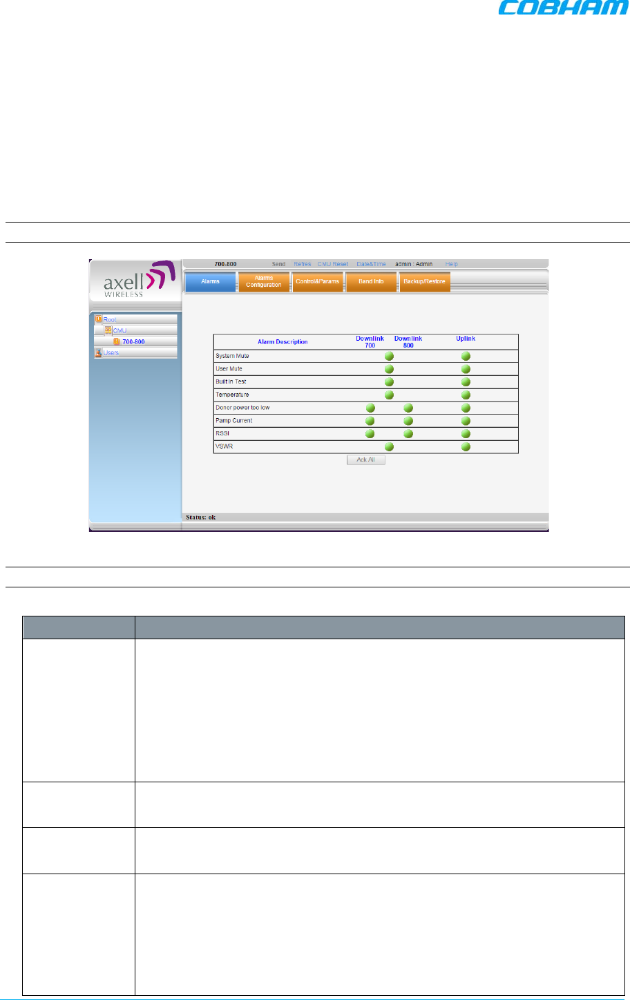
D-MBR 3707-3708 PS NFPA CLASS B SIGNAL BOOSTER
PRODUCT DESCRIPTION AND USER’S MANUAL
www.cobham.com/wireless Cobham Wireless – Coverage Date: 6-Set-15
Page | 62 Doc. No. 00060CDUM Rev. 1.0
7.4 Band-Level Alarms and Troubleshooting
The Alarms tab displays any alarms generated by the bands. The tab is common to both bands.
To display the Band Level Alarms tab
From the left pane, select the 700-800 item and choose the Alarms tab. The relevant alarms are
displayed.
When at fault, each generated alarm is displayed according to the factory set values for that alarm,
as Minor (yellow), Major (orange) or Critical (red).
NOTE: The alarm settings can be modified via the Alarms Configuration tab.
See the following page for alarm descriptions.
NOTE: Use the ACK ALL button to reset ALL displayed alarms.
Alarm Fault and most probable cause and Recommendation
System Mute Description. Generates an alarm when Booster amplification is
automatically
muted.
Possible causes: Temperature failure, Synthesizer failure,
Hardware failure, High RSSI power DL/UL when the shutdown mechanize is
on.
Recommended action: Check the LED and other alarm from the Booster.
Contact Cobham Wireless Support
User Mute Description: Manual shutdown performed by operator from the Web GUI.
Recommended action: Review unit’s log
Built In Test Possible causes: Hardware failure, Circuitry failure, Software failure
Recommended action: Contact Cobham Wireless Support
Temperature Description: Booster
temperature is exceedingly high due to excessive
external heat.
Recommended action: Check the Booster case for external causes (sun,
hot environment, air flow is blocked). Eliminate the reason for excessive
heat.

D-MBR 3707-3708 PS NFPA CLASS B SIGNAL BOOSTER
PRODUCT DESCRIPTION AND USER’S MANUAL
Cobham Wireless – Coverage Date: 6-Set-15 www.cobham.com/wireless
Doc. No. 00060CDUM Rev. 1.0 Page | 63
Alarm Fault and most probable cause and Recommendation
Donor Power
Too Low Description: Signal from the Donor antenna (DL) is too low - relatively to
the desired output signal configured by the user.
Recommended action:
Check the Donor/Base connections and antenna position. Check the signal
level of the Donor/Base antenna.
If the alarm is still raised, then you can raise, the value of the DL Output
Threshold Delta[dBm] as needed
.
(PAmp) Current Description: Power Amplifier current is not within limits (too high or too
low). If the Mute option is enabled, then this is not a fault since it indicates
low Power Amplifier current caused by the mute.
Recommended action: Check the LEDs status in the Booster and Contact
Cobham Wireless service support.
RSSI Description: Generates an alarm when a high
donor
input signal causes
system gain reduction
VSWR Description: This alarm is triggered when the return loss of the Downlink or
Uplink antenna or cable connection exceed the allowed limit.
This alarm provides an indication of the status of the cable/antenna
connected to the antenna. If a cable/antenna is defective, the VSWR is
decreased and the alarm is triggered.
Recommended action: Check the cable.
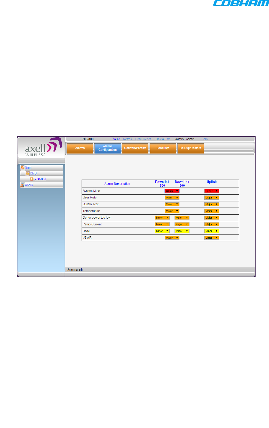
D-MBR 3707-3708 PS NFPA CLASS B SIGNAL BOOSTER
PRODUCT DESCRIPTION AND USER’S MANUAL
www.cobham.com/wireless Cobham Wireless – Coverage Date: 6-Set-15
Page | 64 Doc. No. 00060CDUM Rev. 1.0
7.5 Modifying Alarm Severities
The Alarms Configuration tab is used to modify the factory set level (minor, major or critical) of
specific alarms when they are activated.
To modify the Alarm Severities
From the left pane, select 700-800 item and choose the Alarms Configuration tab. When
activated due to a fault, the alarm is displayed in the selected color. The color corresponds to the
alarm level.
Each alarm can be set to one of the following levels: Minor (yellow), Major (orange) or Critical (red).
Figure 7-4. Modifying Alarm Severities
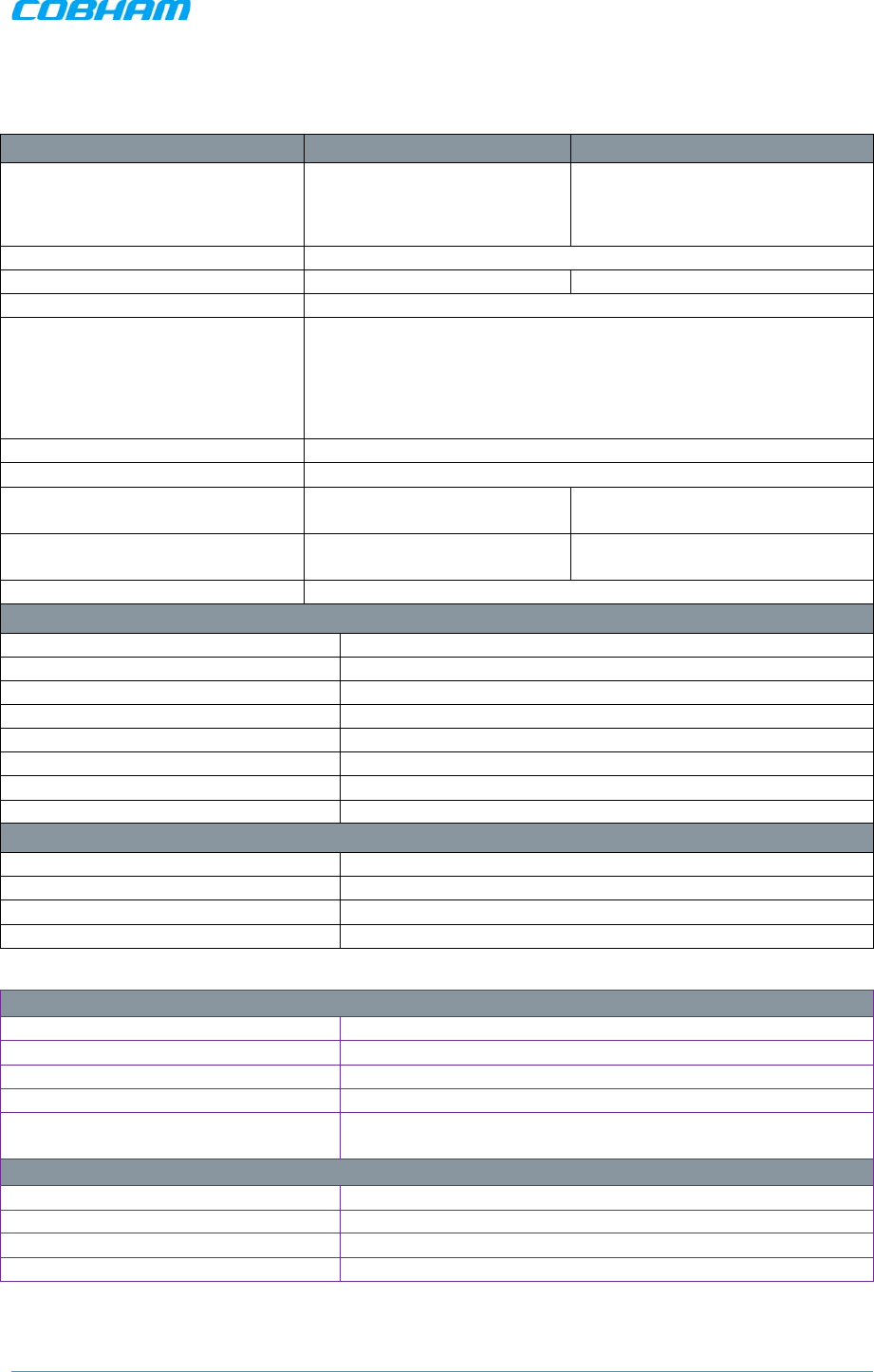
D-MBR 3707-3708 PS NFPA CLASS B SIGNAL BOOSTER
PRODUCT DESCRIPTION AND USER’S MANUAL
Cobham Wireless – Coverage Date: 6-Set-15 www.cobham.com/wireless
Doc. No. 00060CDUM Rev. 1.0 Page | 65
Appendix A – Booster and Charger Specifications
Electrical Downlink Uplink
Frequency Range:
SMR 700MHz ,D block
SMR 700MHz
SMR 800MHz
758 - 763 MHz
763 - 775 MHz
851 - 869 MHz
788 - 793 MHz
793 - 805 MHz
806 - 824MHz
Passband Gain 55 to 95 dB Adjustable in 1 dB steps
Passband Ripple ± 2.5 dB ± 2.5 dB
Gain attenuation range 30 dB
Filter Bandwidth (SMR 700MHz) (*)
Filter Bandwidth (SMR 800MHz) (*) Programmable 75KHz to 1MHz at 12.5KHz steps, 1MHz-17MHz at
200KHz steps
Programmable 75KHz to 1MHz at 12.5KHz steps, 1MHz-18MHz at
200KHz steps
Number of filters in SMR 700MHz Up to 12
Number of filters in SMR 800MHz Up to 12
Composite Output Power SMR
700MHz + 37 dBm + 27 dBm
Composite Output Power SMR
800MHz + 37 dBm + 27 dBm
Noise Figure @ Maximum Gain 5.0 dB
General
Dimensions W x D x H 21.3 x 15 x 12.3 inches (540 x 382 x 313 mm)
Power Supply
36-76 VDC
Power Consumption 350 W
Total RF Input Power (no damage) +10 dBm
Impedance Level
50 Ohm
RF Connector N-type, Female
VSWR 1.5:1 maximum
Compliance IC/FCC
Environmental
Operating Temperature -5 to 122° F (-10° C to +50° C)
Humidity 10% to 90% Condensed
Weight 73 lbs. (33kg)
Enclosure
Aluminium (NEMA4/IP-66)
(*) Every filter above 10MHz utilize 2 FPGA resources
Charger specs
Dimensions W x D x H 13.78” x 18.1” x 5.7” (350 mm x 460 mm x 145 mm)
Power Supply 110VAC
Power Consumption
50 Watt
Dry contact alarms 3 relays for AC fail, charger fail and low battery
Charging time ( 200AH) external
batteries 20 hours
Environmental
Operating Temperature -5 to 122° F (-10° C to +50° C)
Humidity 10% to 90% Condensed
Weight
28.8 lbs. (13kg)
Enclosure Aluminium (NEMA4/IP-66)