PBE Europe as Axell Wireless DMBR37073708PS Class B Booster User Manual
Axell Wireless Class B Booster Users Manual
UserManual.wiki
>
PBE Europe as Axell Wireless
>
DMBR37073708PS User Manual
Users Manual
Navigation menu
Upload a User Manual
Namespaces
Wiki Guide
HTML
PDF
Info
Views
User Manual
Discussion / Help
Navigation
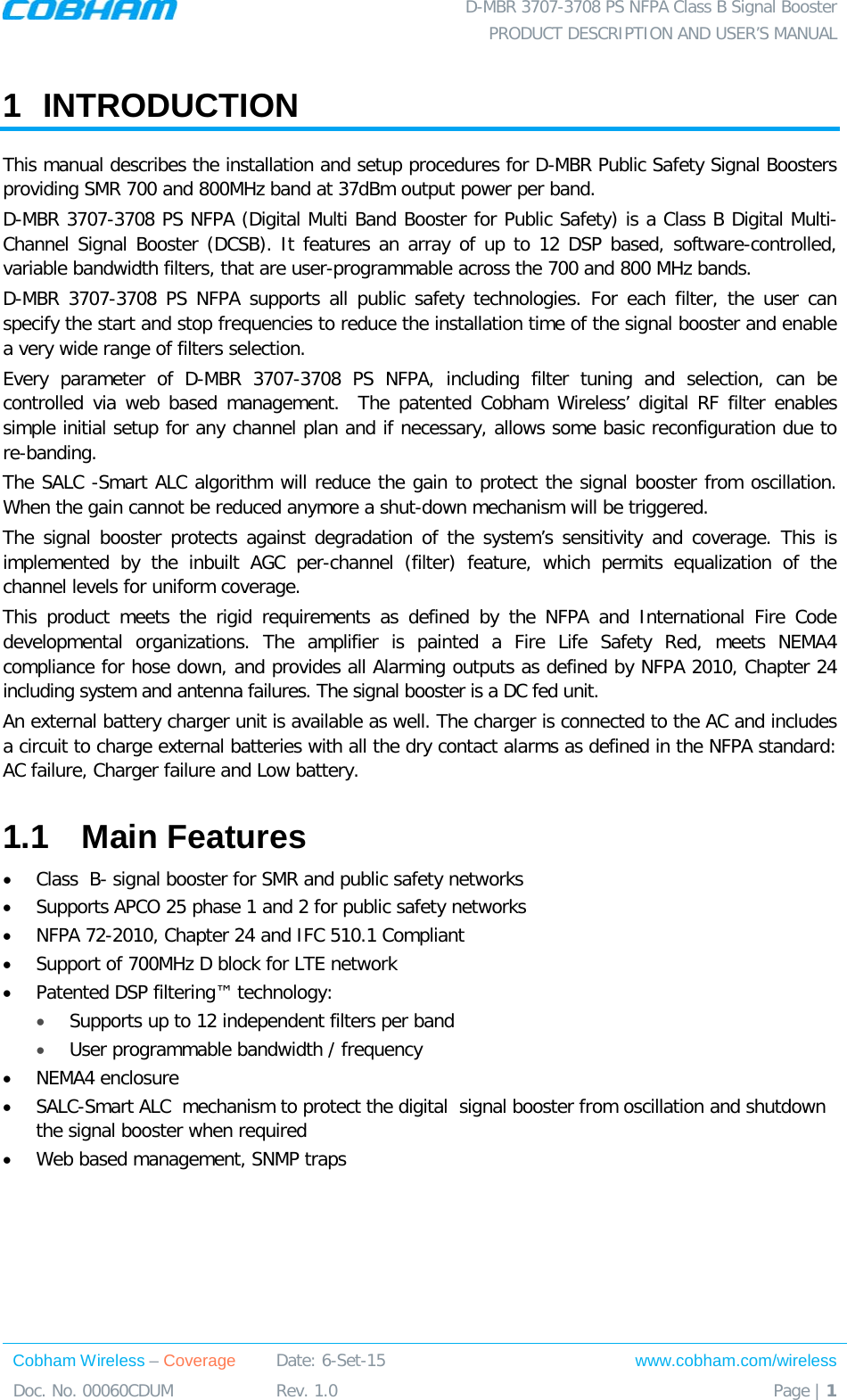
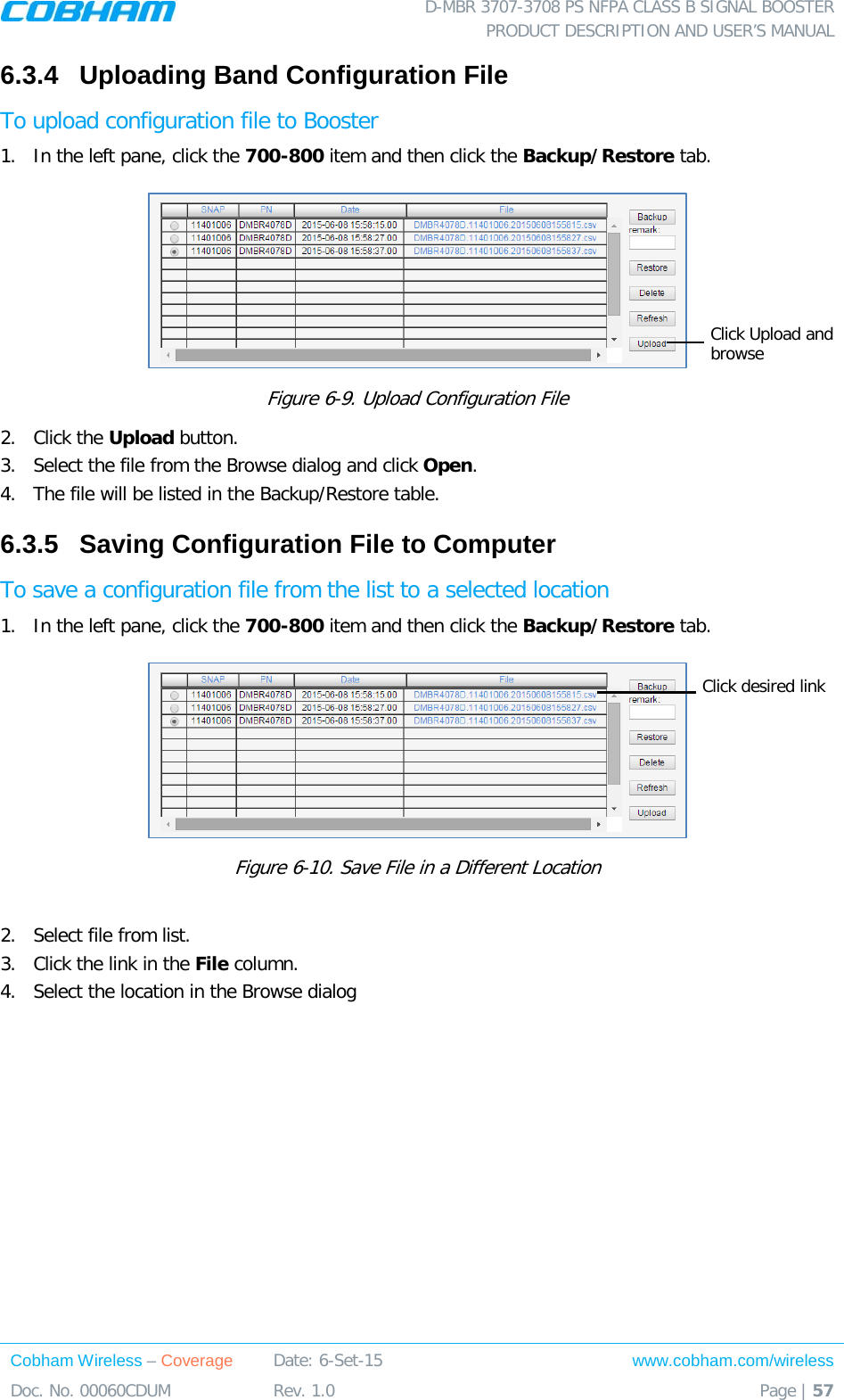
![D-MBR 3707-3708 PS NFPA CLASS B SIGNAL BOOSTER PRODUCT DESCRIPTION AND USER’S MANUAL www.cobham.com/wireless Cobham Wireless – Coverage Date: 6-Set-15 Page | 8 Doc. No. 00060CDUM Rev. 1.0 2.2.2.2 Installation Criteria Installation requirements: • An indoor antenna should be installed at a convenient location. It should be free of metallic obstruction. • Install the Service Antenna at the designated height and tune it roughly toward the Service coverage area. • Installation of this antenna must provide a minimum separation distance of 28 cm from any personnel within the area. Note: If the power is divided into more than 5 antennas that have a large coverage area than the separation distance can be less than 28 cm. • Cable and jumper loss is at least 2dB. 2.2.3 Outdoor Installations For applications in which the Mobile antenna is installed outdoors, the antenna type is chosen according to the available infrastructure (single-pole or horizontal installation). In addition, isolation between the donor and service antennas must be taken into account when selecting the location of the antennas. 2.2.3.1 Recommended Antennas The antenna type depends on the installation: • For vertical Single Pole installations a high side lobe suppression antenna is required. • For horizontal installations either on two separate poles or on two sides of one building a high front to back ratio antenna is required. Specifications: • Maximum antenna gain for outdoor operation 9dBi. • Cable and jumper loss is at least 2dB. • [Gain Antenna – Cable loss] should not exceed 7dB Installation requirements: • Installation of this antenna must provide a minimum separation distance of 62 cm from any personnel within the area. NOTE: The Single Pole and Horizontal Installations are described in section 2.2.3.2 and 2.2.3.3.](https://usermanual.wiki/PBE-Europe-as-Axell-Wireless/DMBR37073708PS/User-Guide-2814019-Page-16.png)

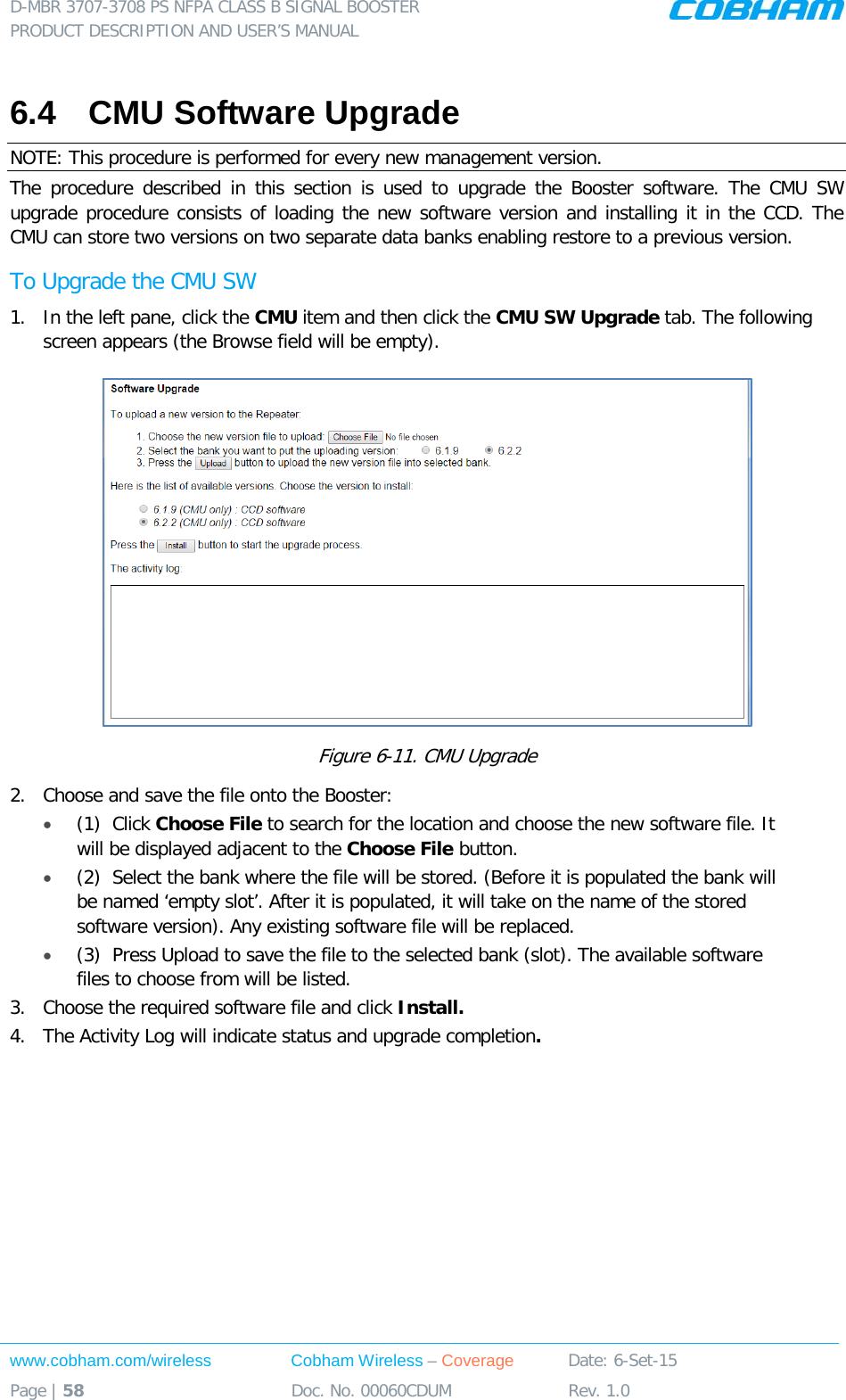
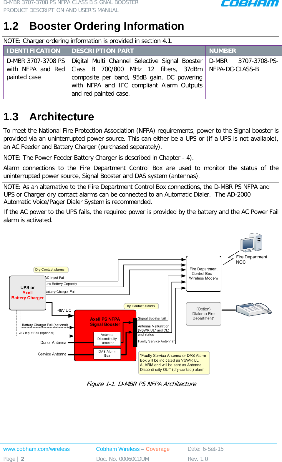
![D-MBR 3707-3708 PS NFPA CLASS B SIGNAL BOOSTER PRODUCT DESCRIPTION AND USER’S MANUAL Cobham Wireless – Coverage Date: 6-Set-15 www.cobham.com/wireless Doc. No. 00060CDUM Rev. 1.0 Page | 63 Alarm Fault and most probable cause and Recommendation Donor Power Too Low Description: Signal from the Donor antenna (DL) is too low - relatively to the desired output signal configured by the user. Recommended action: Check the Donor/Base connections and antenna position. Check the signal level of the Donor/Base antenna. If the alarm is still raised, then you can raise, the value of the DL Output Threshold Delta[dBm] as needed. (PAmp) Current Description: Power Amplifier current is not within limits (too high or too low). If the Mute option is enabled, then this is not a fault since it indicates low Power Amplifier current caused by the mute. Recommended action: Check the LEDs status in the Booster and Contact Cobham Wireless service support. RSSI Description: Generates an alarm when a high donor input signal causes system gain reduction VSWR Description: This alarm is triggered when the return loss of the Downlink or Uplink antenna or cable connection exceed the allowed limit. This alarm provides an indication of the status of the cable/antenna connected to the antenna. If a cable/antenna is defective, the VSWR is decreased and the alarm is triggered. Recommended action: Check the cable.](https://usermanual.wiki/PBE-Europe-as-Axell-Wireless/DMBR37073708PS/User-Guide-2814019-Page-71.png)