PBE Europe as Axell Wireless MBF4103SERIES High Power Multiband Fibre fed Band Selective Booster User Manual
Axell Wireless High Power Multiband Fibre fed Band Selective Booster
UserManual.wiki
>
PBE Europe as Axell Wireless
>
MBF4103SERIES User Manual
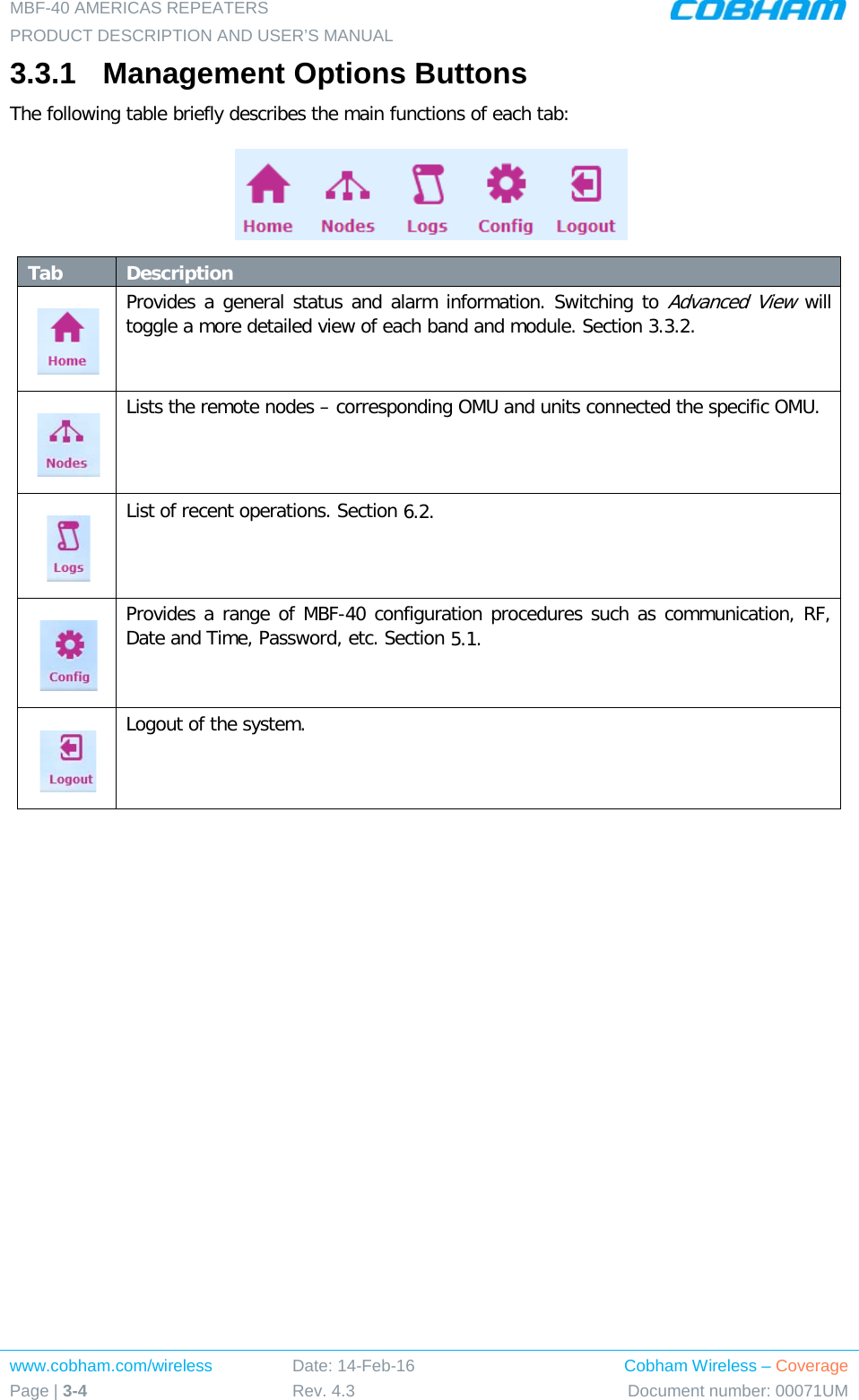
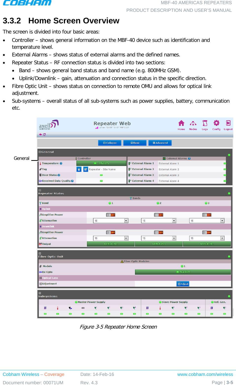
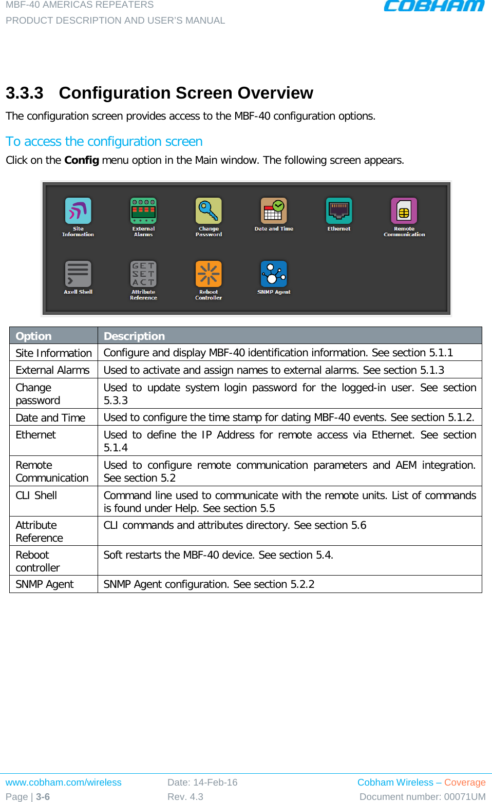
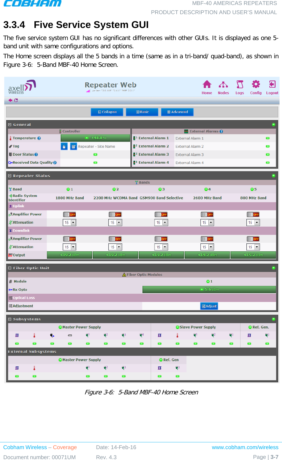
User Manual
Navigation menu
Upload a User Manual
Namespaces
Wiki Guide
HTML
PDF
Info
Views
User Manual
Discussion / Help
Navigation
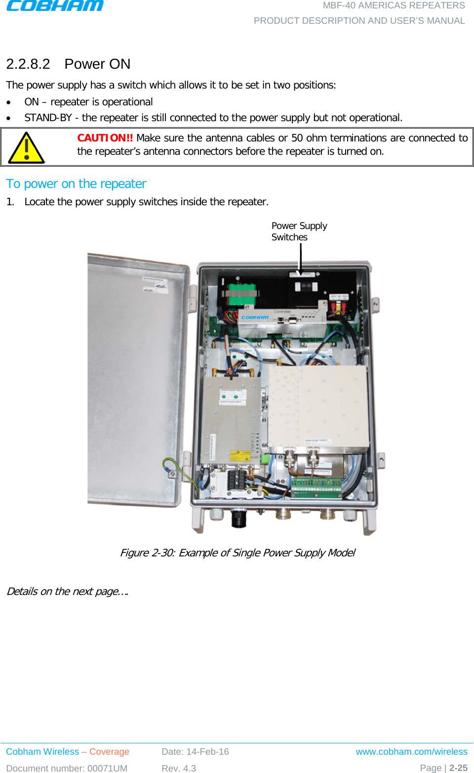
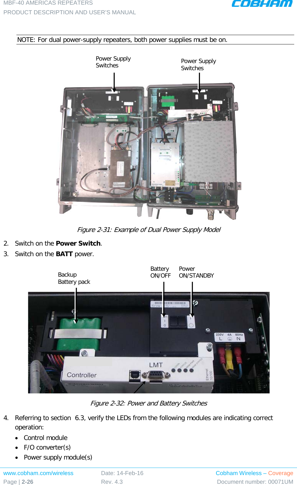
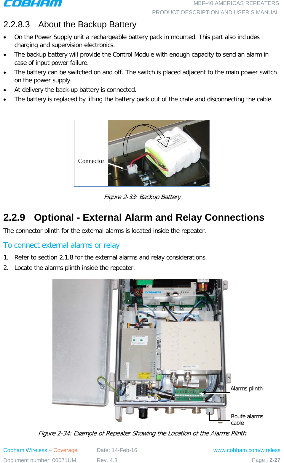
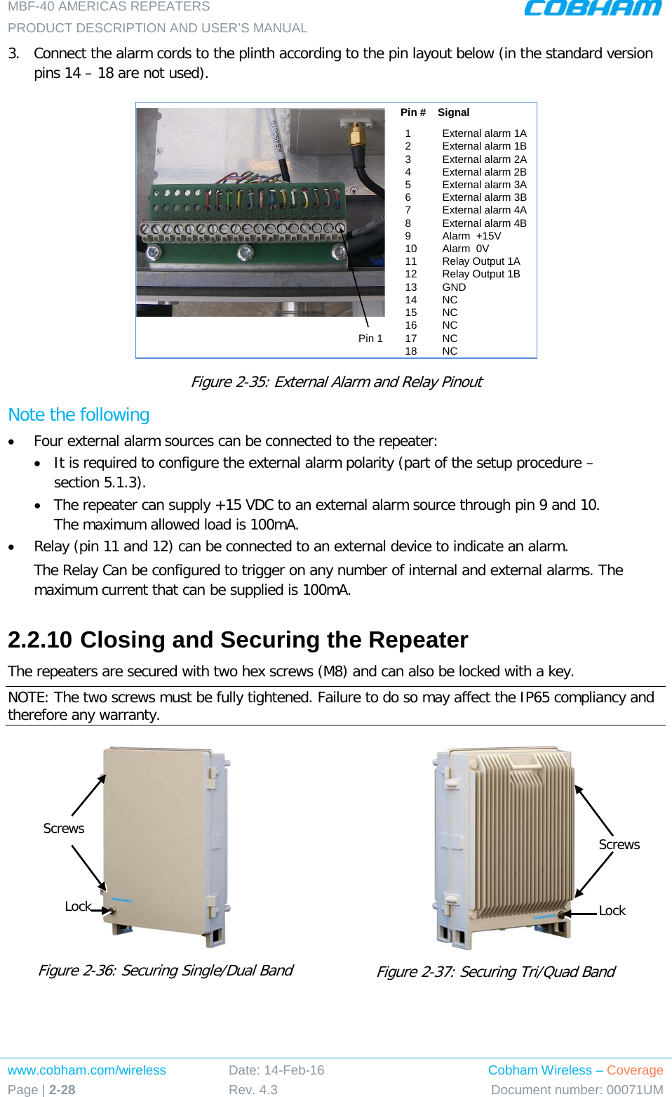
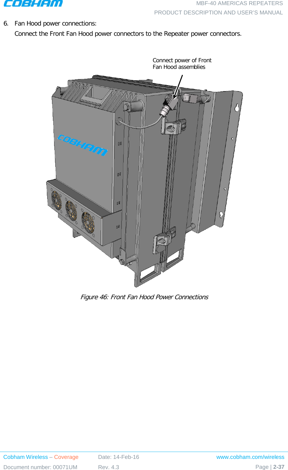
![MBF-40 AMERICAS REPEATERS PRODUCT DESCRIPTION AND USER’S MANUAL www.cobham.com/wireless Page | 2-2 Date: 14-Feb-16 Rev. 4.3 Cobham Wireless – Coverage Document number: 00071UM 2.1.1.1 Required Antenna Information The following antenna requirements, specifications and site considerations should be met. • Type of installation – indoor or outdoor • Service area type and size • Antenna type and characteristics • Height • Length and type of coaxial cable required for connecting the Service antenna to the Remote and the attenuation. 2.1.1.2 Recommended Antennas The Service antenna is installed indoors, where the type of antenna depends on the application. Specifications: • One or a combination of the following antennas can be used: Ceiling Mount Patch antenna, Wall Mount Patch antenna, Corner Reflector. • Choose an antenna with high side lobe attenuation which enables maximum isolation from other service/ mobile antennas. • Net gain [Gain Antenna – Cable loss] must not exceed 9 dBi • Antennas with gain < 9 dBi can be connected directly to the MBF-40 ports. • Higher gain antennas may be connected to the MBF-40 ports along with adequate cable and splitting losses Typical antenna types: • Indoor Dome 2.1 dBi; beam width 360° • Indoor Panel 4.2 dBi; beam width 106° • Radiating Cable Typically < -50 dBi](https://usermanual.wiki/PBE-Europe-as-Axell-Wireless/MBF4103SERIES/User-Guide-3211253-Page-22.png)
![MBF-40 AMERICAS REPEATERS PRODUCT DESCRIPTION AND USER’S MANUAL www.cobham.com/wireless Page | 2-4 Date: 14-Feb-16 Rev. 4.3 Cobham Wireless – Coverage Document number: 00071UM 2.1.2.2 FCC et IC conformité de l'installation intérieure L'antenne de service est installé à l'intérieur, où le type d'antenne dépend de l'application.: • Un ou une combinaison des antennes suivantes peuvent être utilisées: Antenne Patch pour montage au plafond, antenne Patch pour montage mural, Réflecteur en Coin. • Choisissez une antenne à haute côté atténuation du lobe qui permet une isolation maximum des autres services / antennes mobiles. • Gain net [Gain Antenna - la perte de câble] ne doit pas dépasser 9 dBi • Les antennes à gain < 9 dBi peut être connectée directement aux ports MBF-40. • Antennes à gain plus élevées peuvent être connectés aux ports MBF-40 avec des pertes de câble et de division adéquates. 2.1.2.3 Critères d'installation de l'antenne d'installation d'intérieur Déterminer la configuration de l'installation de l'antenne, selon les exigences de transmission et les conditions du site d'installation. Exigences d'installation: • Une antenne intérieure doit être installée à un endroit pratique. Il doit être libre de tout obstacle métallique. • Installez l'antenne de service à la hauteur désignée et l'accorder à peu près vers la zone de couverture du service. • L'installation de cette antenne doit fournir une distance minimale de séparation de 190 cm de tout le personnel dans la région 2.1.2.4 Indoor Installations Service/Mobile Antenna Requirements Determine the antenna installation configuration, according to the transmission requirements and the installation site conditions. Installation requirements: • An indoor antenna should be installed at a convenient location. It should be free of metallic obstruction. • Install the Service Antenna at the designated height and tune it roughly toward the Service coverage area. 2.1.2.5 Outdoor Installations For applications in which the Service/Mobile antenna is installed outdoor, the antenna type is chosen according to the available infrastructure (single-pole or horizontal installation). In addition, isolation between the donor and service antennas must be taken into account when selecting the location of the antennas. 2.1.3 RF Cable Installation Guidelines • For all coaxial connections to/from the Repeater – use high performance, low-loss, 50 ohm coaxial communication cables. • All cables shall be weather-resistant type.](https://usermanual.wiki/PBE-Europe-as-Axell-Wireless/MBF4103SERIES/User-Guide-3211253-Page-24.png)