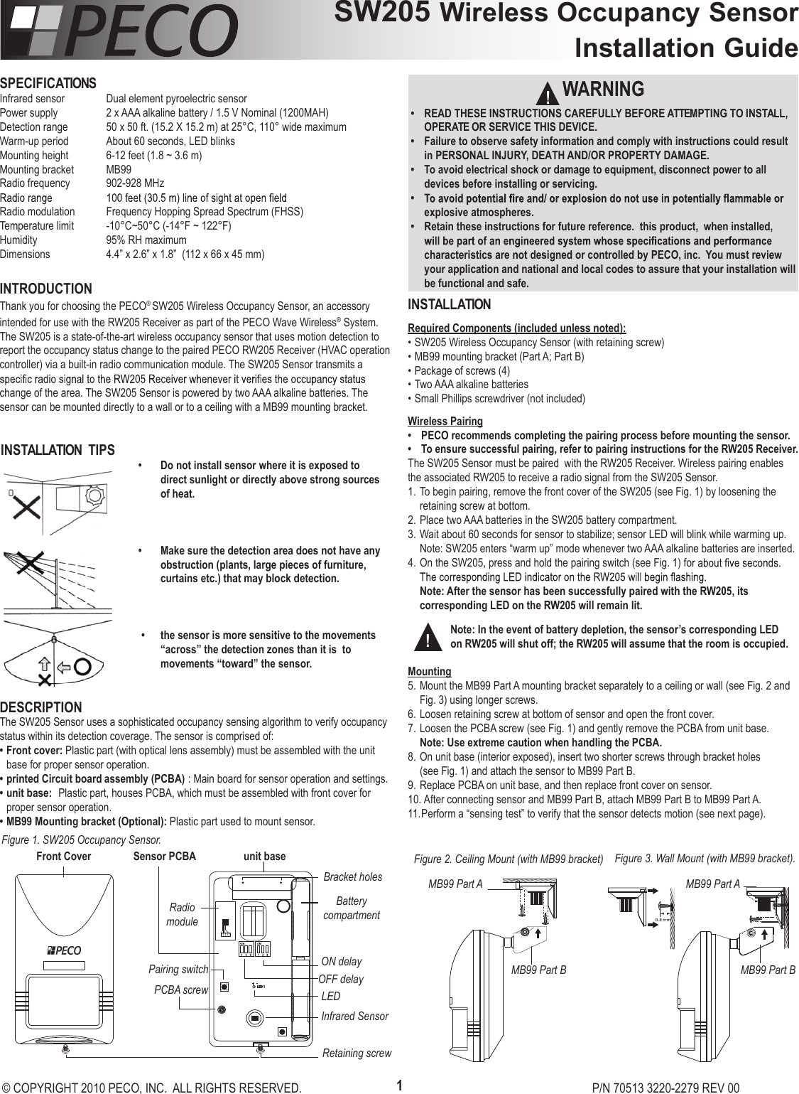
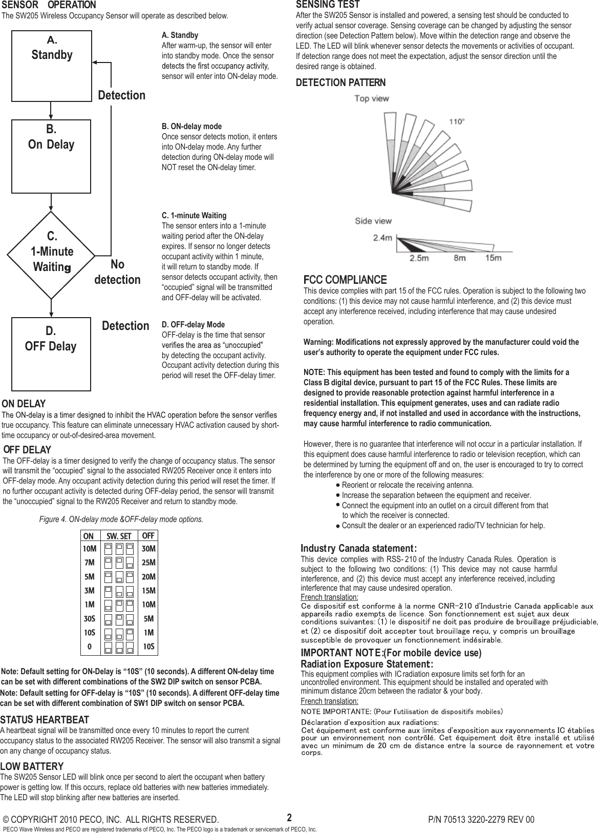
PECO SW205 Wireless Occupancy Sensor User Manual P1

PECO Inc. Wireless Occupancy Sensor P1

User Manual

SW205 Wireless Occupancy Sensor Installation GuideWARNING•  READ THESE INSTRUCTIONS CAREFULLY BEFORE ATTEMPTING TO INSTALL, OPERATE OR SERVICE THIS DEVICE. •  Failure to observe safety information and comply with instructions could result in PERSONAL INJURY, DEATH AND/OR PROPERTY DAMAGE.•  To avoid electrical shock or damage to equipment, disconnect power to all devices before installing or servicing.• explosive atmospheres.•  Retain these instructions for future reference.  this product,  when installed, characteristics are not designed or controlled by PECO, inc.  You must review your application and national and local codes to assure that your installation will be functional and safe.▲!SPECIFICATIONSInfrared sensor  Dual element pyroelectric sensorPower supply  2 x AAA alkaline battery / 1.5 V Nominal (1200MAH)Detection range  50 x 50 ft. (15.2 X 15.2 m) at 25°C, 110° wide maximumWarm-up period  About 60 seconds, LED blinksMounting height  6-12 feet (1.8 ~ 3.6 m) Mounting bracket  MB99Radio frequency  902-928 MHzRadio modulation  Frequency Hopping Spread Spectrum (FHSS)Temperature limit  -10°C~50°C (-14°F ~ 122°F)Humidity     95% RH maximumDimensions   4.4” x 2.6” x 1.8”  (112 x 66 x 45 mm)INTRODUCTIONThank you for choosing the PECO® SW205 Wireless Occupancy Sensor, an accessory intended for use with the RW205 Receiver as part of the PECO Wave Wireless® System. The SW205 is a state-of-the-art wireless occupancy sensor that uses motion detection to report the occupancy status change to the paired PECO RW205 Receiver (HVAC operation controller) via a built-in radio communication module. The SW205 Sensor transmits a change of the area. The SW205 Sensor is powered by two AAA alkaline batteries. The sensor can be mounted directly to a wall or to a ceiling with a MB99 mounting bracket.  DESCRIPTIONThe SW205 Sensor uses a sophisticated occupancy sensing algorithm to verify occupancy status within its detection coverage. The sensor is comprised of: • Front cover: Plastic part (with optical lens assembly) must be assembled with the unit base for proper sensor operation.• printed Circuit board assembly (PCBA) : Main board for sensor operation and settings.• unit base:  Plastic part, houses PCBA, which must be assembled with front cover for proper sensor operation. • MB99 Mounting bracket (Optional): Plastic part used to mount sensor. INSTALLATIONRequired Components (included unless noted):• SW205 Wireless Occupancy Sensor (with retaining screw) • MB99 mounting bracket (Part A; Part B)• Package of screws (4)• Two AAA alkaline batteries• Small Phillips screwdriver (not included)Wireless Pairing•  PECO recommends completing the pairing process before mounting the sensor. •  To ensure successful pairing, refer to pairing instructions for the RW205 Receiver.The SW205 Sensor must be paired  with the RW205 Receiver. Wireless pairing enables the associated RW205 to receive a radio signal from the SW205 Sensor. 1. To begin pairing, remove the front cover of the SW205 (see Fig. 1) by loosening the retaining screw at bottom.  2. Place two AAA batteries in the SW205 battery compartment. 3. Wait about 60 seconds for sensor to stabilize; sensor LED will blink while warming up. Note: SW205 enters “warm up” mode whenever two AAA alkaline batteries are inserted.4. On the SW205, press and hold the pairing switch (see Fig. 1) fo  Note: After the sensor has been successfully paired with the RW205, its      corresponding LED on the RW205 will remain lit. Mounting5. Mount the MB99 Part A mounting bracket separately to a ceiling or wall (see Fig. 2 and Fig. 3) using longer screws.  6. Loosen retaining screw at bottom of sensor and open the front cover. 7. Loosen the PCBA screw (see Fig. 1) and gently remove the PCBA from unit base.  Note: Use extreme caution when handling the PCBA.  8. On unit base (interior exposed), insert two shorter screws through bracket holes  (see Fig. 1) and attach the sensor to MB99 Part B. 9. Replace PCBA on unit base, and then replace front cover on sensor. 10. After connecting sensor and MB99 Part B, attach MB99 Part B to MB99 Part A.11. Perform a “sensing test” to verify that the sensor detects motion (see next page). © COPYRIGHT 2010 PECO, INC.  ALL RIGHTS RESERVED.          P/N 70513 3220-2279 REV 001Figure 1. SW205 Occupancy Sensor.Front Cover unit baseSensor PCBARadio moduleBattery compartmentON delayOFF delayInfrared SensorRetaining screwPairing switchPCBA screwBracket holesLEDFigure 2. Ceiling Mount (with MB99 bracket) MB99 Part AMB99 Part BFigure 3. Wall Mount (with MB99 bracket).MB99 Part AMB99 Part BINSTALLATION  TIPS•  Do not install sensor where it is exposed to      direct sunlight or directly above strong sources    of heat.•  Make sure the detection area does not have any    obstruction (plants, large pieces of furniture,      curtains etc.) that may block detection.•  the sensor is more sensitive to the movements    “across” the detection zones than it is  to         movements “toward” the sensor.Note: In the event of battery depletion, the sensor’s corresponding LED on RW205 will shut off; the RW205 will assume that the room is occupied.  ▲!
SENSOR  OPERATIONThe SW205 Wireless Occupancy Sensor will operate as described below.ON DELAYtrue occupancy. This feature can eliminate unnecessary HVAC activation caused by short-time occupancy or out-of-desired-area movement. OFF DELAYThe OFF-delay is a timer designed to verify the change of occupancy status. The sensor will transmit the “occupied” signal to the associated RW205 Receiver once it enters into OFF-delay mode. Any occupant activity detection during this period will reset the timer. If no further occupant activity is detected during OFF-delay period, the sensor will transmit the “unoccupied” signal to the RW205 Receiver and return to standby mode. STATUS HEARTBEAT  A heartbeat signal will be transmitted once every 10 minutes to report the current occupancy status to the associated RW205 Receiver. The sensor will also transmit a signal on any change of occupancy status. LOW B ATTERYThe SW205 Sensor LED will blink once per second to alert the occupant when battery power is getting low. If this occurs, replace old batteries with new batteries immediately. The LED will stop blinking after new batteries are inserted. SENSING TESTAfter the SW205 Sensor is installed and powered, a sensing test should be conducted to verify actual sensor coverage. Sensing coverage can be changed by adjusting the sensor direction (see Detection Pattern below). Move within the detection range and observe the LED. The LED will blink whenever sensor detects the movements or activities of occupant. If detection range does not meet the expectation, adjust the sensor direction until the desired range is obtained.  A. StandbyAfter warm-up, the sensor will enter into standby mode. Once the sensor sensor will enter into ON-delay mode.B. ON-delay modeOnce sensor detects motion, it enters into ON-delay mode. Any further detection during ON-delay mode will NOT reset the ON-delay timer. C. 1-minute WaitingThe sensor enters into a 1-minute waiting period after the ON-delay expires. If sensor no longer detects occupant activity within 1 minute, it will return to standby mode. If sensor detects occupant activity, then “occupied” signal will be transmitted and OFF-delay will be activated. D. OFF-delay ModeOFF-delay is the time that sensor by detecting the occupant activity. Occupant activity detection during this period will reset the OFF-delay timer. © COPYRIGHT 2010 PECO, INC.  ALL RIGHTS RESERVED.          P/N 70513 3220-2279 REV 002PECO Wave Wireless and PECO are registered trademarks of PECO, Inc. The PECO logo is a trademark or servicemark of PECO, Inc.  Note: Default setting for OFF-delay is “10S” (10 seconds). A different OFF-delay time can be set with different combination of SW1 DIP switch on sensor PCBA.Note: Default setting for ON-Delay is “10S” (10 seconds). A different ON-delay time can be set with different combinations of the SW2 DIP switch on sensor PCBA.Figure 4. ON-delay mode &OFF-delay mode options. DETECTION PATTERNA. StandbyB.On DelayC.1-Minute WaitingD.OFF DelayNodetectionDetectionDetection  FCC COMPLIANCE This device complies with part 15 of the FCC rules. Operation is subject to the following two conditions: (1) this device may not cause harmful interference, and (2) this device must accept any interference received, including interference that may cause undesired operation.Warning: Modifications not expressly approved by the manufacturer could void the user’s authority to operate the equipment under FCC rules. NOTE: This equipment has been tested and found to comply with the limits for a Class A digital device, pursuant to part 15 of the FCC Rules. These limits are designed to provide reasonable protection against harmful interference in a residential installation. This equipment generates, uses and can radiate radio frequency energy and, if not installed and used in accordance with the instructions, may cause harmful interference to radio communication.However, there is no guarantee that interference will not occur in a particular installation. If this equipment does cause harmful interference to radio or television reception, which can be determined by turning the equipment off and on, the user is encouraged to try to correct the interference by one or more of the following measures:  Reorient or relocate the receiving antenna.  Increase the separation between the equipment and receiver.  Connect the equipment into an outlet on a circuit different from that                    to which the receiver is connected.  Consult the dealer or an experienced radio/TV technician for help.ON  OFF 10M7M5M3M1M30S10S030M25M20M15M10M5M1M10SSW. SETIndustry C anada statem ent:  This  device  complies  with RSS-210  of  the  Industry  Canada  Rules.  Operation  is subject  to  the  following  two  conditions:  (1)  This  device  may  not  cause  harmful interference, and (2) this device must accept any interference received, including interference that may cause undesired operation. French translation: Ce dispositif est conforme à la norme CNR-210 d'Industrie Canada applicable aux appareils radio exempts de licence. Son fonctionnement est sujet aux deux conditions suivantes: (1) le dispositif ne doit pas produire de brouillage préjudiciable, et (2) ce dispositif doit accepter tout brouillage reçu, y compris un brouillage susceptible de provoquer un fonctionnement indésirable. =========================================================  IM P O R TA N T N O TE: (For m obile device use) R adiation Exposure Statem ent: This equipment complies with IC radiation exposure limits set forth for an uncontrolled environment. This equipment should be installed and operated with minimum distance 20cm between the radiator & your body. French translation: NOTE IMPORTANTE: (Pour l'utilisation de dispositifs mobiles) Déclaration d'exposition aux radiations: Cet équipement est conforme aux limites d'exposition aux rayonnements IC établies pour  un  environnement non  contrôlé.  Cet  équipement  doit  être  installé  et  utilisé avec un minimum de 20 cm de distance entre la source de rayonnement et votre corps.   SENSOR  OPERATIONThe SW205 Wireless Occupancy Sensor will operate as described below.ON DELAYtrue occupancy. This feature can eliminate unnecessary HVAC activation caused by short-time occupancy or out-of-desired-area movement. OFF DELAYThe OFF-delay is a timer designed to verify the change of occupancy status. The sensor will transmit the “occupied” signal to the associated RW205 Receiver once it enters into OFF-delay mode. Any occupant activity detection during this period will reset the timer. If no further occupant activity is detected during OFF-delay period, the sensor will transmit the “unoccupied” signal to the RW205 Receiver and return to standby mode. STATUS HEARTBEAT  A heartbeat signal will be transmitted once every 10 minutes to report the current occupancy status to the associated RW205 Receiver. The sensor will also transmit a signal on any change of occupancy status. LOW B ATTERYThe SW205 Sensor LED will blink once per second to alert the occupant when battery power is getting low. If this occurs, replace old batteries with new batteries immediately. The LED will stop blinking after new batteries are inserted. SENSING TESTAfter the SW205 Sensor is installed and powered, a sensing test should be conducted to verify actual sensor coverage. Sensing coverage can be changed by adjusting the sensor direction (see Detection Pattern below). Move within the detection range and observe the LED. The LED will blink whenever sensor detects the movements or activities of occupant. If detection range does not meet the expectation, adjust the sensor direction until the desired range is obtained.  A. StandbyAfter warm-up, the sensor will enter into standby mode. Once the sensor sensor will enter into ON-delay mode.B. ON-delay modeOnce sensor detects motion, it enters into ON-delay mode. Any further detection during ON-delay mode will NOT reset the ON-delay timer. C. 1-minute WaitingThe sensor enters into a 1-minute waiting period after the ON-delay expires. If sensor no longer detects occupant activity within 1 minute, it will return to standby mode. If sensor detects occupant activity, then “occupied” signal will be transmitted and OFF-delay will be activated. D. OFF-delay ModeOFF-delay is the time that sensor by detecting the occupant activity. Occupant activity detection during this period will reset the OFF-delay timer. © COPYRIGHT 2010 PECO, INC.  ALL RIGHTS RESERVED.          P/N 70513 3220-2279 REV 002PECO Wave Wireless and PECO are registered trademarks of PECO, Inc. The PECO logo is a trademark or servicemark of PECO, Inc.  Note: Default setting for OFF-delay is “10S” (10 seconds). A different OFF-delay time can be set with different combination of SW1 DIP switch on sensor PCBA.Note: Default setting for ON-Delay is “10S” (10 seconds). A different ON-delay time can be set with different combinations of the SW2 DIP switch on sensor PCBA.Figure 4. ON-delay mode &OFF-delay mode options. DETECTION PATTERNA. StandbyB.On DelayC.1-Minute WaitingD.OFF DelayNodetectionDetectionDetectionFCC COMPLIANCE This device complies with part 15 of the FCC rules. Operation is subject to the following two conditions: (1) this device may not cause harmful interference, and (2) this device must accept any interference received, including interference that may cause undesired operation.Warning: Modifications not expressly approved by the manufacturer could void the user’s authority to operate the equipment under FCC rules. NOTE: This equipment has been tested and found to comply with the limits for a Class A digital device, pursuant to part 15 of the FCC Rules. These limits are designed to provide reasonable protection against harmful interference in a residential installation. This equipment generates, uses and can radiate radio frequency energy and, if not installed and used in accordance with the instructions, may cause harmful interference to radio communication.However, there is no guarantee that interference will not occur in a particular installation. If this equipment does cause harmful interference to radio or television reception, which can be determined by turning the equipment off and on, the user is encouraged to try to correct the interference by one or more of the following measures:  Reorient or relocate the receiving antenna.  Increase the separation between the equipment and receiver.  Connect the equipment into an outlet on a circuit different from that                    to which the receiver is connected.  Consult the dealer or an experienced radio/TV technician for help.ON  OFF 10M7M5M3M1M30S10S030M25M20M15M10M5M1M10SSW. SETIIndust ry  Canada  stat ement :This  device  complies  with  RSS- 210 of  the Industry  Canada Rules.  Operation  is subject  to  the  following  two  conditions:  (1)  This  device  may  not  cause  harmful interference, and (2) this device must accept any interference received, including interference that may cause undesired operation.French translation:   IIMPORTANT  NOTE: ( For mobile  device  use) Radi at i on  Exposure  Stat ement::This equipment complies with IC radiation exposure limits set forth for an uncontrolled environment. This equipment should be installed and operated with minimum distance 20cm between the radiator & your body.French translation:Indust ry Canada  st at ement :  This  device  complies  with RSS - 210 of  the Industry  Canada Rules.  Operation  is subject  to  the  following  two  conditions:  (1)  This  device  may  not  cause  harmful interference, and (2) this device must accept any interference received, including interference that may cause undesired operation. French translation: Ce dispositif est conforme à la norme CNR-210 d'Industrie Canada applicable aux appareils radio exempts de licence. Son fonctionnement est sujet aux deux conditions suivantes: (1) le dispositif ne doit pas produire de brouillage préjudiciable, et (2) ce dispositif doit accepter tout brouillage reçu, y compris un brouillage susceptible de provoquer un fonctionnement indésirable.   IM P O R TA N T N O TE:  (For m obile device use) R adiation Exposure Statem ent: This equipment complies with IC radiation exposure limits set forth for an uncontrolled environment. This equipment should be installed and operated with minimum distance 20cm be tween the radiator & your body. French translation: NOTE IMPORTANTE: (Pour l'utilisation de dispositifs mobiles) Déclaration d'exposition aux radiations: Cet équipement est conforme aux limites d'exposition aux rayonnements IC établies pour  un  environnement non  contrôlé.  Cet  équipement  doit  être  installé  et  utilisé avec un minimum de 20 cm de distance entre la source de rayonnement et votre corps.   B

Navigation menu