PEERLESS Boiler Manual L0308192
User Manual: PEERLESS PEERLESS Boiler Manual PEERLESS Boiler Owner's Manual, PEERLESS Boiler installation guides
Open the PDF directly: View PDF ![]() .
.
Page Count: 48
61/62
Boilers
Installation,
Operation Et
Maintenance
Manual

3-8 90,0 Up to 81.7% AFUE
Natural or LP Gas
Standing Pilot (Steam Only) or Spark Ignition (Hot Water and Steam)
Natural Draft (chimney) Venting
Factory Assembled Sections on Knockdown Boilers
•Reduces Installation Time
Large Water Content
•Ideal for Steam and Large Volume Hot Water Applications
Skim Tapping
•For Cleaning Steam Boilers
Low Profile Design
•Horizontal to Vertical Draft Diverter
•Ideal for Installations with Low Ceilings
Steel Push Nipples
•Provide a Permanent Water Tight Seal Between Sections
•Unaffected by Petroleum and Other Contaminants
Tankless Coils
•For Domestic Hot Water Production on Hot Water Boilers
Deluxe Insulated Enameled Steel Jacket
•Reduces Boiler Heat Loss
•Completely Encloses Gas Valve and Burners
Safety Controls
•Low Water Cut-Offon Steam Boilers
•Flame Roll-Out Shut-OffSwitch
•Blocked Vent Shut-OffSwitch
•Honeywell Operating Controls
•Vent Damper
•Float Type LWCO on Steam Boilers
•Taco 007 Circulator on Packaged Water Boilers
•Tankless Coil for Hot Water Boilers
•Gnmdfos Circulator on Packaged Hot Water Boilers
• Probe Type LWCO on Steam Boilers
Peerless Heater Comparly is pleased to offer one of the most comprehensive warranty programs
icl tile indnstn 1, All Peerless residential cast troll _x_ilers include a fidl one-yea" warranty. A limited.
lifetone warranty is provided.for the cast iron sections ol Peerless residential hot water boilers.
Peerless also provides a limited, ten year warranty ot_ the cast iron sections of its residential steam
boilers. Five and ten year extended warratlties on parts and labor are now available. Pl_'asc consult
Peerl_,ss Heater Company for complete warranty inJbrmation.
PGGRLESS _
CAST IRON BOILERS
Peerless Heater Company * 231 North Walnut Street •Boyertown, PA 19512-1021 •610-3S7-2153 * www.peerless-heater.eom
FAB-61 R1 (3/02 3M)
Printed in US A

pr=-I RLESS o
CAST IRON BOILERS
Series 61
oResidential Gas Boilers
•Packaged or Knockdown
oNatural Draft Venting
oStanding Pilot or
Spark Ignition
QSteam or Hot Water Boilers
oNatural or LP Gas
Water
Steam
QThis large water content boiler
installsin difficultsteam or water
applications.
oAFUE ranges from 76.8%
(standing pilot) to 80.7% (spark
ignition) on steam boilers and
80,3% to 81.7% (spark ignition
only) on water boilers, significantly
exceeding the federal standards
for residential boiler efficiency.
oLow profile design ideal for boiler
installationsin areas with a low
ceiling.
An optional tankless domestic
hot water coil can be installed on
hot water boilers, insuringample
domestic hot water production.
oProbe or float-type low water
cutoff available.
DOE
Heating Capacity
MBH--
Stdg.PilotwlDamper
Seasonal Efficiency
(AFUE)4
Net I=B=R Ratings 3
Steam Steam Water
Sq. Ft. MBH 2MBH 1
225 54 63
304 73 85
4O4 97 113
504 121 140
604 145 168
704 169 196
Spark Ign. wlDamper
Seasonal Efficiency
(AFUE) 4
Water Content
(GaL)
IA,G.A.
I Input
N MBH Water Steam Water I Steam Water I Steam Water Steam
90 73 72 N/A I 76.8 80.5 I 80.6 8.16 4.80
120 98 97 N/A I77.7 81.7 I 80.7 10.32 5.88
160 130 129 N/A I 77,8 81.3 I 80.6 12.48 6.96
200 I 161 161 N/A I 78.0 81.0 I 80.6 14.64 8.04
240 193 193 N/A I 78.1 80.6 I 80.6 16.80 9.12
280 225 225 N/A I 78.3 80.3 I80.6 18.96 18.20
1 Net I=B=R water ratings based on an allowance of 1.15,
2 Net I=B=R steam ratings based on an allowance of 1.333.
3Consult factory before selecting a boiler for installations having unusual piping and pickup requirements, such as intermittent system operation, extensive piping
systems, etc.
4 Heating Capacity and Annual Fuel Utilization Efficiency (AFUE) ratings are based on U.S. Government test. Before purchasing this appliance, read important
information about its estimated annual energy consumptions or energy efficiency rating that is available from your retailer.

7 Sizes 9-15 Sections 320 to 560 MBH Input 80% Combustion Efficiency
Natural or LP Gas
Standing Pilot or Spark Ignition
Natural Draft (chimney) Venting
Factory Assembled Sp/it Block Sections on Knockdown Boilers
•For Ease of Handling
Large Water Content
•Ideal for Steam and Large Volume Hot Water Jobs
Skim Tapping
•For Cleaning Steam Boilers
Low Profile Design
•Horizontal to Vertical Draft Diverter
•Idealfor Installatiolis with Low Ceilings
Steel Push Nipples
•Provide a Permal_ent Water Tight Seal Between S_ctioris
•Unaffected by Petroleum arid Other Cor_tamiTlalltS
Tankless Coils
•For Domestic Hot Water Production o_ Hot Water Boilers
Deluxe Insulated Enameled Steel Jacket
•Reduces Boiler Heat Loss
•Completely Encloses Gas Valve and Burners
Safety Controls
•Low Water Ctlt Q[l'orl Steam Boil_'rs
•HoT_eywell Operating Co_ltrols
•Mar_ltal Reset High Limit Corltrol (12-15 Section)
•Float Type LWCO orl Steam Boilers
•Tcxl_lcless Coiljor Hol Watcr Boilers
•Moclultxtillg Fi1_rlg Systems (12 15 S<:cliorl}
• F_'I _rid IRI Colltrol S!]slerTls (12 15 Sectioll)
• Prot)t> "I_upe I.WCO o11 Sle(lfll Boilers
_ll lilt" il_(lll._lr'!]. ./Ill I_'_'r'l( '.,_.s ('ollilll_'r('i(¢l _'cl.'q/ _rt)ll I)oih>l_ _ll_'h_(l_ >(I /illl. oil(' ! (>_'lr" tl,_ls't(_ll[ 1. A
lilliilt>(I. It'll !]('(1I II'_llltll_l[/ I)ll I]l(" _'tl._l il'oll ._('t'l_oll._ i.'_ [)l()l'l_ll'_ [i_t (ill (Ollllll<'F('i_ll 11(>I I_ll('I _lll([
,'_l_>(llll I?l_il(>I'_. I+'il'( ' _lll_'l [I'll I I>tlr ('._l_'tl_l(>_l ll'_l_'ltlllll_'_ I)ll l_(It l_ (lll_l I_l!)ol (It't' /loll' ttl'(li[(l!)_('. CAST IRON BOILERS
!'lt>(_._;( ' €'otl.'_ll/I I>_'('t'l_ '.'q_ I h'_ll_'t ( "olllt)_lltt].[O_" _'Oml)lt'f_" it,t_r_t_i_l!] ir!]Oi rIl(llioll.
Peerless Heater Company •231 North Walnut Street *Boyertown. PA 19512 1021 • 610 367-2153 - www.peerless-heater.com
FAB 6_7t9 02 :_,%
pGr=-RLESS o
CAST IRON BOILERS
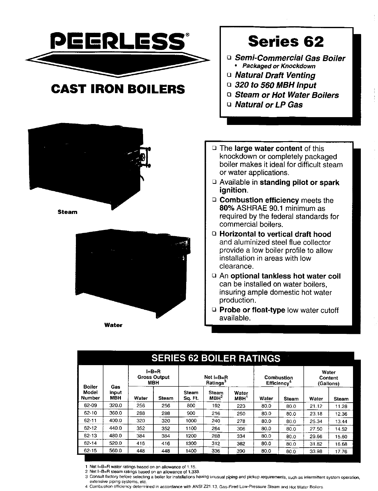
Series 62
oSemi-Commercial Gas Boiler
• Packaged or Knockdown
oNatural Draft Venting
o320 to 560 MBH Input
oSteam or Hot Water Boilers
oNatural or LP Gas
Steam
Water
oThe large water content of this
knockdown or completely packaged
boiler makes it ideal for difficult steam
or water applications.
oAvailable in standing pilot or spark
ignition.
oCombustion efficiency meets the
80% ASHRAE 90.1 minimum as
required by the federal standards for
commercial boilers.
OHorizontal to vertical draft hood
and aluminized steel flue collector
provide a low boiler profile to allow
installation in areas with low
clearance.
r_ An optional tankless hot water coil
can be installed on water boilers,
insuring ample domestic hot water
production.
o Probe or float-type low water cutoff
available.
I=B=R Water
Gross Output Net I=B=R Combustion Content
MBH Ratings 3 Efficiency 4 (Gallons)
Model Input Steam Steam Water
Number MBH Water Steam Sq. Ft. MBH2MBH 1Water Steam Water Steam
62-09 320.0 256 256 800 192 223 80.0 80.0 21.12 11.28
62-10 360.0 288 288 900 216 250 80.0 80.0 23.18 12.36
62-11 400.0 320 320 1000 240 278 80.0 80.0 25,34 13.44
62-12 440,0 352 352 1100 264 306 80.0 80.0 27.50 14.52
62-13 480.0 384 384 1200 288 334 80.0 80.0 29.66 15.60
62o14 520.0 416 416 1300 312 362 80.0 80.0 31.82 16.68
1 Net I=B=R water ratings based on an allowance 011.15.
2 Net I=B=R steam ratings based on an allowance of 1.333.
3 Consult factory before selecting a boiler for installations having unusual piping and pickup requirements, such as intermittent system operation,
extensive piping systems, etc
4 Combustion efficiency determined in accordance with ANSf Z21 13, Gas-Fired Low-Pressure Steam and Hot Water Boilers

I
J
K
L
M
N
O
P
Q
R
m
Boiler
Model
Number
62-09
62-10
62-11
62-12
62-13
62-14
62-15
Steam Water
3/4" Pressure Gauge* Limit Control (Models 09-11)
3/4,, N/A Operating Control (Models 12-15)
3/4" N/A Limit Control (Models 12-15)
V2" N/A Temperature-Pressure Gauge
V2" Gauge Glass and Low Water Cutoff N/A
2" Return Return
3/4" Secondary Probe Low Water Cut-Off N/A
3/4" Safety Relief Valve Safety Relief Valve
1V2" Skim Tapping N/A
¾" Primary Probe Low Water Cut-Off N/A
3o4-
L£_'T SID_ £RON_ RIGH TSIDE
• Pressure gauge, operating control and I_mitcontrol on Models 62 12 to 62 15
Jacket Right of Distance Rear of Distance ,..
Jacketto Betw. Two Jacketto Flue Between !Rt. Sup.& C_uetOy
Width Depth Top to Fir. c/I of Flue Flue c/l's c/I of Flue Size Tappings Tap. Inter. Chimney
"A .... B.... C.... D.... D1.... E.... F.... G.... GI"
39 V2" 30V4" 35" 14" 11%#' 4%s" 2-6" 333/." N/A 9" 9" x 20'
43%" 30V4" 35" 15" 13_V_6" 4%8" 2-7" 37%" N/A 9" 9" x 20'
47_¾_' 30V4" 35" 16" 15_3/lS" 4%4' 2-7" 42V16" N/A 9" 9" x 20'
52" 30V4" 35" 18" 15_%#' 6_/_6" 2-8" 46V4" 21_/_6" 10" 10" x20'
56 Ys" 30V4" 35" 19" 18V_6" 6Vls" 2-8" 50%" 253/16" 10" 10" x 20'
60%6" 30_/4" 35" 20VI4' 20¾e" 6V_6" 2-8" 54%6" 25z/_6" 10" 10" x 20'
64W_6" 30V4" 35" 22W' 203Ae" 6%6" 2-8" 58"A_" 29s/_6"10" 10" x 20'
STEAM WATER
, , i
t t "L
Boiler
Model
Number
62-09
62-10
62-11
62-12
62-13
62-14
62-15
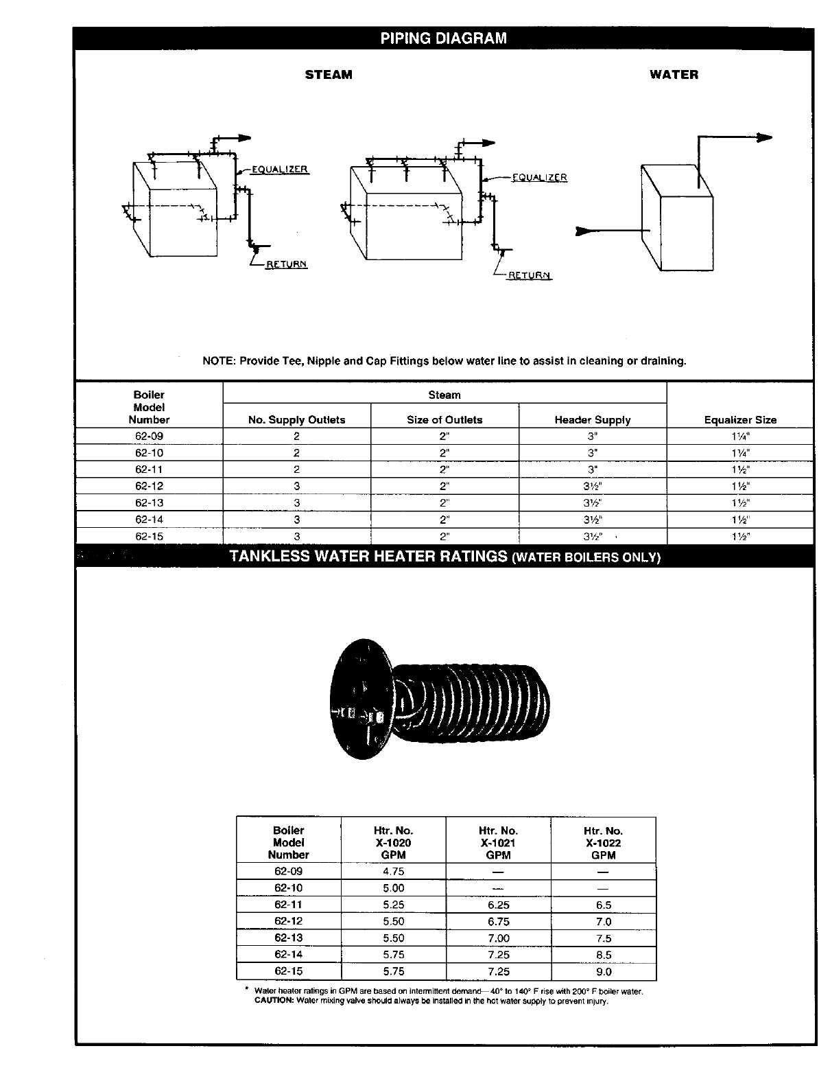
NOTE: Provide Tee, Nipple and Cap Fittings below water line to assist in cleaning or draining.
Steam
No. Supply Outlets
2
2
2
3
3
3
3
Size of Outlets
2"
2"
2"
2"
2"
2"
Header Supply
3 _=
3"
3"
3V2"
31/2''
31/2'`
31/2" ,
Equalizer Size
1V4"
11/4"
1V2"
1V2"
1V2"
1W'
1V2"
Boiler
Model
Number
62-09
62-10
62-11
62-12
62-13
62-14
62-15
Htr. No.
X-1020
GPM
4,75
5.00
5.25
5.50
5.50
5.75
5.75
Htr. No. Htr. No.
X-1021 X-1022
GPM GPM
6.25
6.75
7.00
7.25
7.25
m
6.5
7.0
7.5
8.5
9.0
*Water healer ratings in GPM are based on intermittent demand40 °to 140_ Frise with 200 °FbOiler water
CAUTION: Water mixing valve should always be installed in the hot water supply to prevent injury,
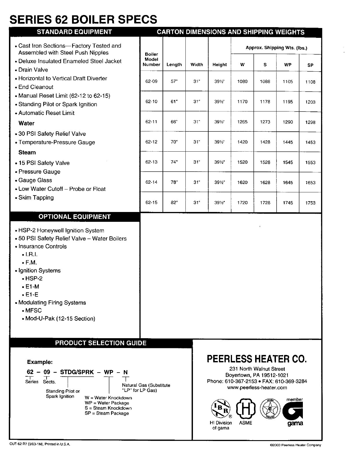
SERIES 62 BOILER SPECS
_-_-_ LlJl-J_vd_id
• Cast Iron Sections--Factory Tested and
Assembled with Steel Push Nipples
•Deluxe Insulated Enameled Steel Jacket
• Drain Valve
• Horizontal to Vertical Draft Diverter
•End Cleanout
• Manual Reset Limit (62-12 to 62-15)
• Standing Pilot or Spark Ignition
• Automatic Reset Limit
Water
• 30 PSI Safety Relief Valve
• Temperature-Pressure Gauge
Steam
•15 PSI Safety Valve
• Pressure Gauge
• Gauge Glass
• Low Water Cutoff - Probe or Float
• Skim Tapping
• HSP-2 Honeywell ignition System
• 50 PSI Safety Relief Valve - Water Boilers
• Insurance Controls
•I.R.I.
,F.M.
• Ignition Systems
• HSP-2
• E1-M
• E1-E
• Modulating Firing Systems
• MFSC
• Mod-U-Pak (12-15 Section)
Approx. Shipping Wts. (Ibs.)
Boiler
Model
Number ILength IWidth !Height IW S
I II!
62-09 I57" 31" I 391/2" I 1080 I1088
I I I I
62-10 I 61" 3t" J391/2" J1170 I 1178
I I I I
62-11 I 66" 31" I 391/2`' ! 1265 I 1273
I I I ]
62-12 I 70" 31" I 391/2" ]1420 I 1428
I II!
62-13 I 74" 31" I 391/2" I 1520 I 1528
I IIJ
62-14 I 78" 31" I 391/2'' ] 1620 I 1628
I I I I
62-15 I 82" 31" I391/2" I 1720 1 1728
WP SP
1105 1108
1195 1203
1290 1298
1445 1453
1545 1553
1645 1653
1745 1753
nnam
Example:
62 - 09 - STDG/SPRK - WP - N
Series Sects. Natural Gas (Substitute
Standing Pilot or "LP" for LP Gas)
Spark Ignition W = Water Knockdown
WP = Water Package
S = Steam Knockdown
SP = Steam Package
PEERLESSHEATERCO.
231 North Walnut Street
Boyertown, PA 19512-1021
Phone: 610-367-2153 • FAX: 610-369-3284
www.peerless-heater.com
HI Division ASME garNa
of gama
CUT-62 F_7(3/03-1M), Printed in U SA. _003 Peedess Heater Company

Readcarefullybeforebeginningwork.It witlsavetime.Studythe includeddrawings.
Theequipmentshallbe installedin accordancewith thoseinstallationrequirementsofthe authorityhavingjurisdictionor, in theabsenceof such
requirements,to thecurrenteditionof the NationalFuelGas CodeZ223.1/NFPA54.
Whererequiredbythe authorityhavingjurisdiction,theinstallationmustconformto the standardforControlsand SafetyDevicesfor AutomaticallyFired
Boilers,ANSI/ASMECSD-I.
A-ACCESSIBILITY CLEARANCES
1. Toprovidefor reasonableconditionsof accessibility,the followingminimumclearancesare recommended.
a. 24" betweenthesides, top,back andfront of theboilerand adjacentwall or otherappliance,when accessis requiredfor servicing.
B - CLEARANCEFROMCOMBUSTIBLECONSTRUCTION
1. Thedesignofthisbelieriscertifiedforthefollowingclearancesfromcombustibleconstruction:
MODELS61-03thru61-08;62-09thru 62-11
18"fromrear
6"from rightand left sides
30" fromtop- front alcove
6"fromflue connector
6"from steamandhot waterpipes
MODELS62-12thru62-15
24" fromsidesand rear
55" fromtop
6"fromflueconnector
6"fromsteam andhotwater pipes
2. CAUTION:This boileris NOTDESIGNCERTIFIEDforinstallationon carpetingor combustibleflooring.
C -AIR FORCOMBUSTIONANDVENTILATION
1. Be certainadequatefacilitiesare availableto provideairfor satisfactorycombustionandventilation.
2. AppliancesLocatedin UnconfinedSpaces:
a. Installationsin unconfinedspaceswith conventionalconstructionand largeareas:thesupplyof airfor combustionandventilationcan usually
beconsideredadequate,
3, AppliancesLocatedonConfinedSpaces:
If allair for combustionand ventilationis to comefromwithinthebuilding:two openingsshallbe providedwithone openingcommencingwithin
12inchesof thetop andone openingwithin12 inchesof the bottomof theenclosure.Theseopeningsshall notbe locatedcloserthan 3 inches
fromeitherthe topor bottomof the enclosureand shallbe openintoareascommunicatingfreely withtheoutdoors,The areaof eachopening
shallbe equalto one squareinch per 1000BTU/HRof totalinput ratingof all applianceswithinthe enclosure,witha minimumof 100square
inchesfor eachopemng,
If allair for combustionand ventilationis to comefrom outsidethebuilding:two openingsshallbe providedwithone openingcommencing
within12 inchesof thetop and oneopeningcommencingwithin12 inchesof the bottomof theenclosure.Theseopeningsshall notbe located
closerthan 3 inchesfromeitherthe top or bottomof theenclosureandshallcomreunicatedirectlyor by ductswith theoutdoors.The areaof
eachopeningshall beequalto onesquareinch per 4000 BTU/HRof totalinputrating.If ductsare usedto conveythe air,verticalductsrequire
areasof onesquareinch per4000 BTU/HR:horizontalductsrequireone squareinchper 2000 BTU/HR,Ductsshallhavethe samecross
sectionalareaas the full area of the openingsto whichtheyconnect.
c. Theupperopeningsare essentialfor maintenanceof propercirculationofairwiththe boilerroomand reasonableambienttemperatureinorder
to maintainpropercontroltemperatures.
D - SETTING UP BOILER -PACKAGEDUNITS
1. A PackagedBoiler is factoryassembledbeforebeingcrated.Allcontrolsand accessoriesnecessaryfor operationof the boilerare attachedand
electricallywired.
2. Thedraft hoodis packedin a separatecarton.
3. When boileris removedfromthe crate,carefulinspectionshouldbe made andthecarrier notifiedof any damagefound.
4. Providea goodlevelfoundation.
5. Placethe boileron the foundationnearand in properpositionwith relationtothe chimney,andas centralizedwith respecttothe heatingsystemas
practical,
6. The openingsin thebasesides are providedfor admittingsecondaryair and mustneverbe closed.
7. Removeiackettop andattach drafthoodto flue collectorwithtwo #10x 1/2"sheetmetalscrewsprovided.Replacejackettop.
8. The burnersare installedin the boiler.Theyare securedin placefor shipmentbywoodstripewiradto the Burnermixingtube.Cut thewiresand
removethewood strips.
9. The gas manifoldandocntrolassemblyare madeup gas tight,completelyfactoryassembledand installedas integralcomponentsof thebase
assembly.See Figure12.

D - SE'I-rlNG UP BOILER - UNASSEMBLED UNITS
I-- ASSEMBLEDBLOCKS
1--The boilersectionsandbase,Models61-03thru61-07arefactoryassembled.Removeshippingskidfromtheboilerbase.If boilerisa61-08,
or62-09thru62-15beginassemblyas notedin PartII "SplitBlockAssembly".
2--Providea goodlevelfoundation,The Boilershouldbe locatedasneartothechimneyandcentralizedwithrespecttotheheatingsystemas
possible.
3--Open controlbox.Removecontroland manifoldassembly,Referto Figure6 andattachmanifoldto boilerwithfourV4-20x 1"machinescrews
and nutsprovided.Figures43 thru45 show thestandardcontrolassembliesusedon Models61-08thru 62-15.
4 Openflue collectorcarton.Removeflue collectorand Hi Tempropeandlay rope ontop of boileragainstbeadprovided.SeeFigure7.
5--Place fluecollectoron topof ropeand attachto boilerwithtwo1/4"-20studs,washersandhex nutsprovided,throughfluecollectorbrackets
into thetapped lugs providedontopof theboilerend sections.Drawbolts downsnugly.SeeFigure8,
6--Attach cast ironclean-outplate10clean-outopeningon leftside of the boiler.This plate, HiTempropeand mountinghardwaremay befoundin
thecontrolbox referred1opreviously.
7--Remove the burnersfromthecontrolboxand install.Installeachburnerby slippingtheopeninginthe venturioverthe orificespud.Insertthe
pin on thebottomof theburnerintothe holeprovidedin theflangeon the basebackplate.SeeFigure9.The Burnerswith pilotsattachedmust
be installedas follows:Note:Hookbolt isprovidedon models62-11through62-15.
ModelNo. No.Pilots
61-03 1
61-04 1
61-05 1
61-06 1
61-07 1
61-08 2
62-09 2
62-10 2
62-11 2
62-12 2
62-13 2
62-14 2
62-15 2
Location of Pilot
Between2nd and 3rd BurnerfromLeft
Between4th and5th BurnerfromLeft
Between4th and5th BurnerfromLeft
Between4th and 51hBurnerfromLeft
Between4th and 5thBurnerfromLeft
Between4th and5th Burnerfrom Leftand4th and5thfrom Right
Between4th and5th BurnerfromLeft and4th and5thfrom Right
Between4th and 5thBurnerfromLeft and4th and5thfrom Right
Between4th and5th Burnerfrom Leftand4th and 5thfrom Right
Between4th and 5thBurnerfromLeft and4th and 5thfrom Right
Between4th and 5thBurnerfromLeft and41hand5thfrom Right
Between41hand5th BurnerfromLeft and6th and7thfrom Right
Between6th and7th BurnerfromLeft and6th and7thfrom Right
8..-Removepilot tubingfromcontrolbox and installbetweengas valveandpilot. Referto figures43 through45.
9--If boileris to incorporatea tanklessheaterfordomestichot water,installinopeningprovidedin the rightside of the boiler.Six mountingbolts
3/8"16 x3/4 are rovldedBe sure rubber asketi I
( - ) p " • g "sbetweencoverplateandtheboier, Ifboiler doesnot incorporatea fanklessheater,a
blankcoverplateis providedwithrubbergasketand bolts.One3/4"pipeopeningis providedin the platefor the operatingand/orlimit control.
This 3/4"tappingis alsousedfor the pressuregaugeonthe steamboiler,
10--For suggestedpipingto fanklessheaterreferto Figure23.
DANGER:Installmixingvalveinhotwatersupplypiping.Watertemperatureover 125°Fcan causesevereburnsinstantlyor deathfromscalds,
2

I:'ROC_"OUR lr FOR STACKING PALLtr'rq
II-- SPLITBLOCKASSEMBLY
1--Boiler sectionsfor Models61-08,62-09thru 62-15are shippedintwo parts. Removeskidfrom each blockof sections.
2--Place each blockof sectionson the stackedskids.See Fig.A. Becertainto removethesmall blocksonthetop skid.See Fig.B,
3--To clean nippleportsand removeprotectivecoating, usea wire brush andmineralspiritsor lacquerthinner.Makecertainthereare no burrs
aroundthe outsideedgeof the ports.
4--Spread a thincoatof PeerlessNippleSealerin the nippleports, NEVERON NIPPLES.
5--Insert the push nipples,withthe chamferededge out. Makecertaintheyare cleanand free ofburrs.
6--Apply a thin coatof PeerlessNippleSealerto the ropegroove.Press5/8"Dia. ropeinto thegroove.Thenipplesealeractsas an adhesiveto
holdthe ropein placeuntil thesecgonsare drawnup.
7--Arrange both blocksso that protrudingnippleentersthe openport.Caremustbe takento keepnipplesstraightand blocksaligned.
8--Insert drawrodsthroughthe nippleports.Make certainthat the3/4"drawrod is usedon the large nipple.Pay particularattentionto the
placementof the drawwashers.See Fig.A.
9--Before startingdraw,oil thethreadsand betweenthe nutsandwashers.
10--Tightenthe hexnutsanddraw boilerevenlyuntilthe small padsoneach sectionjust touch.
11--After boiler is drawn,removethedraw rodsand cut 5" from the 6V4" threadedend.Inserttherod throughthe lugs oneachendsectionand
tightenthehex nutshandtight.
12--Attach3/8"Dia.ropeto baseback plateby layingropeacross topof back plateflange and in ropegrooveon eachendof backplate.Usenipple
sealerto hold ropein place.Referto figures9 & 12.Attachbase backplate by meansof V4"-20x lr/2" machinescrewsandnutsfurnished.
The base back plateis attachedto back of boiler.SeeFigure8. Be certainthatthe flange portionof plate istowardsthe insideof the boiler.
Note: hook bolt isprovidedonmodels 62-11through62-15only.
13--Install pressuregage,drain valve,water supplylinewith shutoffvalve,and meansto ventair.Plugunusedtappings.
14--Fill boilerwith water,ventingair as water levelrises.Pressurizeboilerto 75-85 psig.Do notexceed85 psig.
15--Verify pressureis maintained.Checkall jointsand fittingsfor leaks.
16--Drain boiler.Removepressuregage,drain valve,watersupplyand airvent.ContinuewithStep2 underD-1.
E-JACKET ASSEMBLY
A.Wrap-AroundRearJacket PanelStylefor Models61-03thru 61-06
Thisstylejacket designincorporatesa BackJacketPanelaspart of eachRightand Left SideJacketPanel.TheBackJacketPanelis formedwhena
portion of each Side Panelis bent atperforationsto rearof boile_:
I, Inserttwo (2) 1/4-20x 1"studs intapped holesat bottomof RightEndSection.SeeFigure t.
2. Placethe RightSide Panelalong right sideof boiler blockandalign the slotsof the mountingbrackets,(atbottomof jacketpanel),withthe 1/4-20x
1"studs.Attachjacket panel to boilersectionwithtwo (2) 1/4"nutsandwashers.SeeFigureI.
3. Placethe Left Side Panelalongleft side of boiler blockand attachto boilersectionin samemanneras performedfor RightSide Panel.
4. Bendat theperforationsof the Right SidePanelto form half of the BackJacketPanel.Dothe sameat perforationsof the LeftSidePanel.At the
centerjoint overlapof the Back Panel,attach panelswiththree (3) #10x 1/2"sheetmetalscrews.See Figure2.
Positionthe InnerFrontPanelbetweenthe Leftand RightSide Panels.Align the two (2) mountingholes,on eachsideflangeof the InnerFront
Panel,with the clearanceholesin eachSide Paneland attachwith four(4) #10x 1/2"sheetmetalscrews.See Figure4.

6. PlacetheSecondaryAirCoverDooratbottomofInnerFrontPanel.ThetopbendoftheCoverDoorslipsoverthetopreversebendatcutout
openingoftheinnerFrontPanel.RefertoFigure11.
7. AtlachDraftHoodtoFlueCollectorwithtwo(2)#10x1/2"sheetmetalscrews.RefertoFigure10.
8. AttachtheLowerFrontPaneltothebottomtrontoftheLeftandRightSidePanelswithtwo(2)#10x1"sheetmeta_screws.SeeFigure4.
9. PositionTopJacketPanelsotheflangesoverlapSideJacketPanelsandairlouversareatthefrontoftheboiler.Securewithsix(6)#10x1/2"sheet
metalscrews.SeeFigure4.
10.AttachtheCleanOutCoverPlatePaneloveropemnginLeftSideJacketPanet,withfour(4)#10x1/2"jacketscrews.SeeFigure4
11.ThemanilaenvelopethatcontainstheInstallationManualalsocontainstheboilerratinglabel,clearancetocombustiblesplate,Lighting/Operating
instructionplateorlabelandwiringdiagramlabel.SeaFigure5forlocationofplatesandlabels.Attachplateswith#6x3/8"screwsprovided.
12.PositiontheRemovableFrontPanelinplacebyslidingthePanelunderthefrontflangeoftheTopPanelandthendownuntilitrestsonLowerFront
Panel.
B.IndividualBackJacket PanelStyle for Models61-07thru 62-t5
Thisjacketstyle hasa separateBackJacketPanelthatis attachedto individualRightand LeftSidePanels.
1. AttachSide Panelsper instructionsin #1thru 3 above.SeeFigure 1.
2. Positionthe BackJacketPanelon the insideof theLeft and RightPanelflangesand attachwithsix (6) #10x !/2" sheetmetalscrews.SeeFigure3.
3. Followinstructionsaboveper #5thru 12for assemblyof remainingjacket panels.
SIDE PANEL ATFACHMENT
FIGURE 1
-,_ RIGHT SIDE PANEL
ONEPIECERIGHT
SIDEANDREAR
PANEL
1/4" WASHER
1/4" NUT
J
J
ONE PIECE LEFT
SIDE AND REAR
PANEL
REAR VIEW WRAPPER
STYLE JACKET
(61-03THRU 61-06)
FIGURE 2
LEFTSIDEPANEL
RIGHT
SIDE
PANEL
REAR VIEW OF BACK PANEL
(61-07 THRU 62-15)
FIGURE 3
BACKPANEL
4
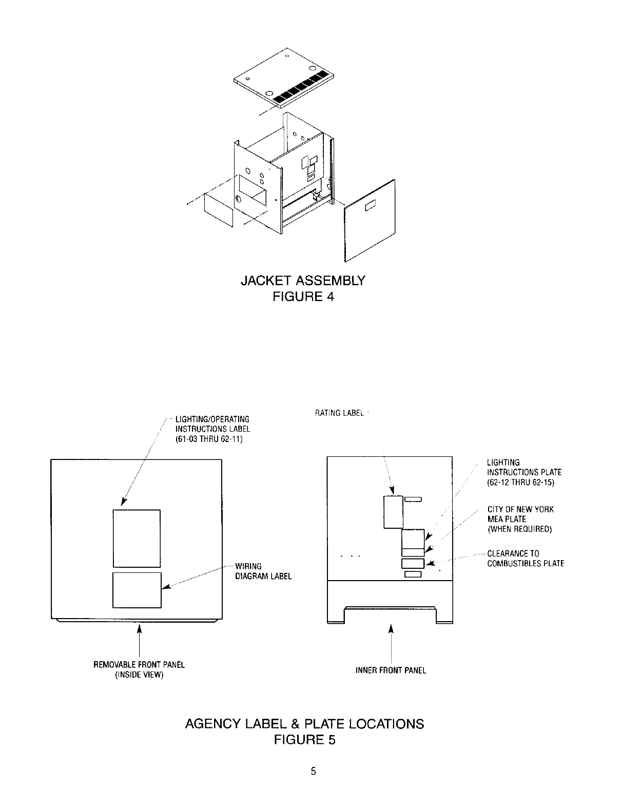
JACKET ASSEMBLY
FIGURE 4
/
/
#,
,LIGHTING/OPERATING
,INSTRUCTIONSLABEL
(61-63 THRU 62-11)
"WIRING
_J
/jJ DIAGRAM LABEL
RATINGLABEL
LIGHTING
INSTRUCTIONSPLATE
(62-12 THRU 62-15)
CITYOFNEWYORK
•MEAPLATE
(WHENREQUIRED)
CLEARANCETO
COMBUSTIBLESPLATE
REMOVABLEFRONTPANEL
(INSIDE VIEW) INNER FRONTPANEL
AGENCY LABEL & PLATE LOCATIONS
FIGURE 5

FIGURE 6
FRONT BOILER VIEW
FIGURE 7
FRONT TOP BOILER VIEW
T_6"- !_UNC NUT & WASHER
_BASE BACK_
-- PLATE
BURNER MANIFOLD-_
HOOK BOLT _'w
FIGURE 9
HOOK BOLT ASSEMBLY
FIGURE8
REAR BOILERVIEW
FIGURE 10
FLUE COLLECTOR/DRAFT HOOD
.f,
H
FIGURE 11
SIDE VIEW OF INNER FRONT
AND COVER DOOR
-"IGURE 12
TOP CUT VIEW OF MANIFOLD
BURNER AND BASE BACK PLATE
6

F- VENTING
A.General
1--For connectionto gasventsor chimneys,ventinstallationshall bein accordancewith Part7, Ventingof Equipment,of thecurrenteditionof the
NationalFuelGas Code,ANSIZ223.1/NFPA54,orapplicableprovisionsof the localbuildingcodes.
2--Draft: Sufficientdraft mustbe availableforremovalof productsof combustion.If draftis notadequate,spillageof the productsof combustion
will occurat the bottomoutletof the draft hood.Ifsuch a conditionshouldexistcheck theflue and chimneyto determinecauseof insufficient
draft.It is also importantthat ampleairis availablein theboiler roomto facilitatedraft.
3--Vent connectorshouldslope upwardat least 1/4"per lineal footbetweenthe drafthood outletandthechimney.
4--Flue orvent connectormustbe insertedinto butnot beyondtheinsidewall of the chimneyflue.
5--Vent connectorsservingappliancesventedby naturaldraft shallnot beconnectedinto anyportionof mechanicaldraftsystemsoperating
underpositivepressure.
6--Horizontal portionsof theventingsystemsshall be supportedto preventsaggingby use of metalstrappingor equivalentmeansandbe located
at no morethan 12 ft. intervals.
7--When anexistingboileris removedfrom a commonventingsystem,thecommonventingsystemis likelyto be too large forproperventingof
theappliancesremainingconnectedto it.
At thetime of removalof anexistingboiler,thefollowingstepsshall be followedwith eachapplianceremainingconnectedto the common
ventingsystemplacedin operation,whilethe otherappliancesremainingconnectedto thecommonventingsystemare not inoperation.
a.Sealany unusedopeningin thecommonventingsystem.
b.Visuallyinspectthe ventingsystemfor propersize and horizontalpitchand determinethereisno blockageor restriction,leakage,corrosion
and otherdeficiencieswhichcouldcausean unsafecondition.
c.Insofaras is practical,closeall buildingdoorsand windowsand alldoorsbetweenthespacein whichtheappliancesremainingconnected
to thecommonventingsystemare locatedandotherspacesof the building.Turnon any clothesdryersandany appliancenotconnectedto
the commonventingsystem.Turnon any exhaustfans,suchas rangehoodsand bathroomexhausts,so theywilloperateat maximum
speed.Donot operatea summerexhaustfan.Close fireplacedampers.
d.Placein operationtheappliancebeing inspected.Followthe lightinginstructions.Adjustthermostatso appliancewill operatecontinuously.
e.Testfor spillageat the drafthood reliefopeningafter 5 minutes of mainburneroperation.Usethe flameof a match orcandle, orsmokefrom
a cigarette,cigar orpipe.
f. After it hasbeendeterminedthat eachapplianceremainingconnectedto thecommonventingsystemproperlyventswhentested as
outlinedabove,returndoors,windows,exhaustfans,fireplacedampersandany othergas-burningapplianceto their previousconditionsof
use.
g.Anyimproperoperationof thecommonventingsystemshouldbe correctedso theinstallationconformswith thecurrenteditionof the
NationalFuel GasCode,ANSIZ223.1/NFPA54.Whenresizingany portionof the commonventingsystem,the commonventing system
should beresizedto approachminimumsize as determinedusingtheappropriatetableslocatedin the chapter"Sizingof CategoryI Venting
Systems",inthe currenteditionof theNationalFuelGas Code,ANSIZ223.1/NFPA54.
8--Single WallTypeVentPipeshouldbefurnishedbetweenthedrafthood andchimney.If theventconnectorshallbe locatedin orpassthrougha
cold area,the ventconnectorshall be of listed double-wallTypeB or L material.

B,VentDamperInstallation
1 Ventdampersare providedon models61-03through61-08as standardequipment.
2--Unpack thevent damperandfollowthese instructionsandthe installationinstructionsin theventdampercarton.Observethecautionsand
warmngthat accompanyall instructions.Do notmodifyventdamperor boilerdrafthood
3--The ventdampercanbe mounteddirectlyonto the drafthood outletcollar,or in theventpipingclose to the boiler.Seefigures14 and 15, Be
sure directionof flow arrowlocatedon dampercollar,is pointingawayfromdraft hoodcollarand damperpositionindicatoris visibleafter
installation,Forinstallationwithdampermountedin the horizontalposition,mountthe damperas shownin figure15to avoidexcessiveheat
and possiblecondensationdrips on the damperoperatingcontrol.
4--Do not useoneventdamperto controltwo or moreheatingappliances.Seefigure 13.
5 Makecertainthatthe minimumclearancesprovidedinthe ventdampermanufacturersinstructionsare maintainedandthatadequatespaceis
providedfor damperaccessand service.
6--A wiring harnessis packedwiththe ventdamperwith pluginconnectionsat eachendof theharness.Connectsmallerendintodampermotor
receptacleand connectotherendto boileraquastatrelay_imit(on waterboilermodelsequippedanL8148Eor L8124Elimitcontrol),orboiler
junctionbox (onsteam boilermodels),
7--Damper mustbe in theopen positionwhenappliancemainburnersare operating.
OTHERHEATING
APPLIANCE
I[_ OTHER
HEATING
APPLIANCE
INCORRECT CORRECT
Figure13:VentingMultipleAppliances
8

SLOPE UP
A MINIMUM
OF 1/4"
PER FOOT -m
VENT
DAMPER
AS REQUIRED
DRAFT HOOD
OUTLET
Figure14:VentingwithVentDamperinVerticalPosition
/- VENT TO
SLOPE UP VENT /CHIMNEY
A MINIMUM DAMPER
oF1/4" "7F" 1
PER FOOT_ 11 O'CLOCK
r_
1 O'CLOCK
POSITION
OPERATOR
-CONDENSATION
ZONE
7 O'CLOCK 5 O'CLOCK
POSITION POSITION
DO NOT MOUNT DAMPER
OPERATOR IN SHADED REGION
SECTION A-A
Figure15:VentingwithVentDamperin HorizontalPosition

G - PIPING
1--Hot Water:
a.The recommendedpipinghook-upis shownin Figure17.Also referto PeerlessWaterSurvey.
2--Steam:
a.The recommendedpipinghook-upis shownin Figure16.Pleasenotethat a Hartfordreturn loopis recommendedto be usedonall steam
boilers.Also referto PeerlessSteamSurvey.
3--The reliefvalveand popsafetyvalveshallbe installedby usingthe 3/4"x 3"nippleand 3/4"elbowsuppliedwith theboiler.Referto illustrations
located inSection R - "Ratings,Tappingsand DimensionalData".LargeNPT sizevalvesmaybe installedin supplypiping.
NOTE: IFTHIS BOILERANDDISTRIBUTIONSYSTEMIS USEDIN CONJUNCTIONWITHA REFRIGERATIONSYSTEM.THECHILLED
MEDIUMSHALLBE PIPEDIN PARALLELWITHTHE BOILERAND THEPROPERVALVEAPPLIEDTO PREVENTTHECHILLED
MEDIUMFROMENTERINGTHE BOILER.A DRAWINGILLUSTRATINGTHIS HOOK-UPIS PROWDEDINFIGURE18.
WHENTHEBOILERIS CONNECTEDTOHEATINGCOILSLOCATEDINAIR HANDLINGUNITWHERETHEYMAYBE EXPOSED
TO REFRIGERATEDAIR CIRCULATION,THE BOILERPIPINGSYSTEMMUSTBE EQUIPPEDWITHFLOWCONTROLVALVESOR
OTHERAUTOMATICMEANSTO PREVENTGRAVITYCIRCULATIONOFTHEBOILERWATERDURINGTHECOOLINGCYCLE.
CAUTION:PIPETHEDISCHARGEOFRELIEFVALVETO PREVENTINJURYINTHE EVENTOF PRESSURERELIEE SUGGEST
DISCHARGETOBE PIPEDTODRAIN.PIPEFULLSIZE OFOUTLET.
H - GAS PIPING
1--Gas supplypipingis to be sizedand installedproperlyinorder to providesupplyof gas sufficientto meet themaximumdemandwithoutundue
lossof pressurebetweenthe meterandthe boiler.
2_onsult the followingtablefor propersizing of gaspiping for variouslengthsand diameters.
CAPACITYOF PIPEOF DIFFERENTDIAMETERSAND LENGTHSINCU. FT PERHOURWITHPRESSUREDROPOF 0.3 IN.AND
SPECIFICGRAVITYOF0.60. NOALLOWANCEFORAN ORDINARYNUMBEROF FITTINGSIS REQUIRED,
PipeLength 3/4" 1" 11h"11/2"
Feet Pipe Pipe Pipe Pipe
10 278 520 1,050 1,600
20 190 350 730 1,100
30 152 285 590 890
40 130 245 500 760
50 115 215 440 670
60 105 195 400 610
MULTIPLIERSTO BEUSEDWITH ABOVETABLE,WHENTHE SPECIFICGRAVITYOFTHEGAS IS OTHERTHAN0.60
SpecificGravity 0.5 0.55 0.60 0.65 0.70
Multiplier 1.10 1.04 1.00 0.962 0.926
3.-Locate the droppipe adjacentto,butnotin frontof theboiler.
4--Locate a tee in thedrop pipeat sameelevationas thegasinlet connectionto the boiler.Extendthe droppipeto a pipecap asshownin Figure
19to forma sedimenttrap.
5--Install a groundjoint unionaheadof the gas controlassemblyto permitservicingof the equipment.See Figure19.Somelocalcodesrequirean
additionalshut-offvalve.Ifyour coderequiressucha valve,a suggestedlocationis shownin Figure19.
6_OTE: Wheninstallingboiler besure a pipecompoundresistanttotheactionof liquefiedpetroleumis used.
7--Check pipingfor leaks.Alwayscheck leakswitha waterandsoapsolutionor equal.DONOTUSE A FLAMEFORCHECKINGGASLEAKS,
8--The boilerandits individualshut-offvalvemustbe disconnectedfrom the gas supplypipingsystemduringany pressuretestingof that system
at test pressuresin excessof r/2psig (3.5kPa),
The boiler mustbe isolatedfromthe gassupplypipingsystembyclosing its individualmanualshut-offvalveduringany pressuretestingof the
gassupplypipingsystemat test pressureequalto or lessthan V2psig (3.5kPa).
10

Table1: SteamHeader,Risersand EqualizerSizing
L---RETURN
SUGGESTEDPIPING
t t
ETURN
NOTE:Thereturnfrom systemshouldalwaysenterequalizer
throughHartfordLoop,approximately2"- 4" below
normalwaterline.
Steamheadershouldbe 24" rain.aboveboilernormal
waterline.
Figure16: SteamSupplyand ReturnPiping
Model No.Supply Size of Header Equalizer
No. Outlets Outlets Supply Size
6t-03 1 2" -- 1114"
61-04 1 2" -- 11/4"
61-05 1 2" -- lr_"
61-06 2 2" 21_" 11_"
61-07 2 2" 2+/2" 11_"
61-08 2 2" 3" 11_"
62-09 2 2" 3" 11_"
62-10 2 2" 3" 1!_"
62-11 2 2" 3" 1_"
62-12 3 2" 31_" 11_"
62-13 3 2" 31_" 11_"
62-14 3 2" 31_" tl_"
62-15 3 2" 31_" 11_"
STEAM BOILER
SUGGESTEDPIPING
HOT WATERBOILER
_TOP • w_STt ¥_LV[ (Nomwl_eJrY O_J_W_
Cu_{D _to _ [xF_l_,_ TANK
_ S_T_II_ESS v,_Tl_ ;_'_1_ is _ _Fw°_ ;4(ATW4G<
Figure 17: Hot Water Supply and Return Piping
11
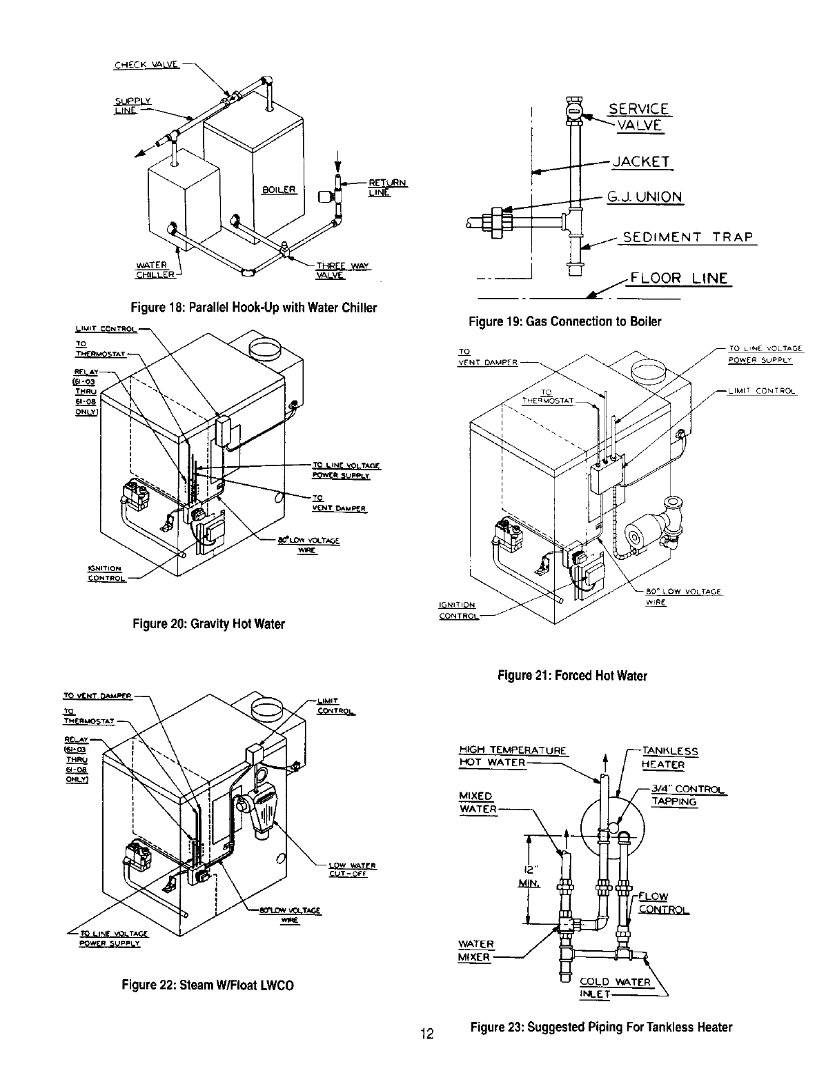
Figure18: ParallelHook-UpwithWaterChiller
J
SERVICE
_JACKET
G.J. UNION
SEDIMENT TRAP
_./FLOOR LINE
Figure19:GasConnectionto Boiler
Figure20:GravityHotWater
Figure22: SteamW/FloatLWCO
Figure21: ForcedHotWater
.HIGH TEMPERATURE
HOT WATER _.
MIXEO
WATER
MIXER
HEATER
"rAPPING
12 Figure23:SuggestedPipingForTanklessHeater
A
c
©o ©
F_
1/2 TAPPINGS
TO MOUNT
9 1/4 LONG
GAUGE GLASS
FROM PROBE
L.WC.O. CARTON
L_ I_
RIGHT SIDE PANEL
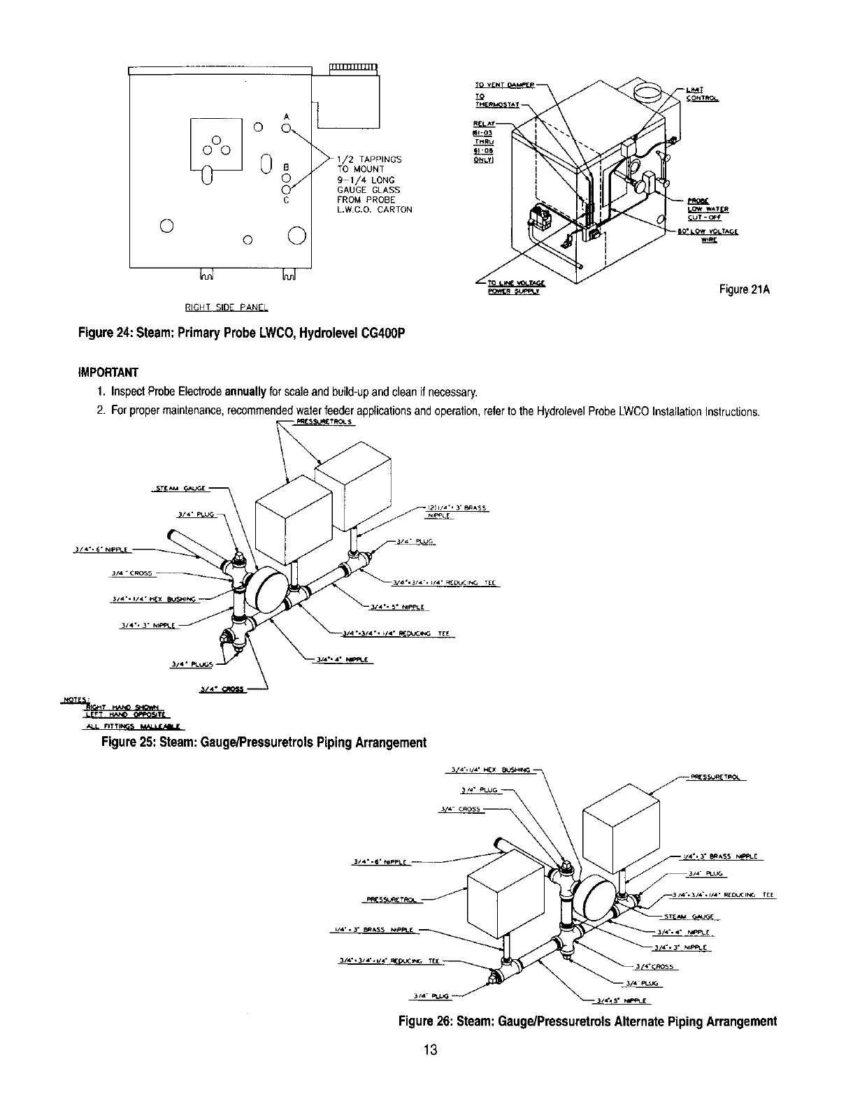
Figure24:Steam:PrimaryProbeLWCO,HydrolevelCG400P
THRU
i1_11 _.
I
I
Figure21A
IMPORTANT
1. InspectProbeElectrodeannuallyfor scaleandbuild-upand cleanif necessary.
2. Forpropermaintenance,recommendedwaterfeeder applicationsandoperation,referto theHydrolevelProbeLWCOInstallationInstructions.
• °
LEFT I';AhlD OPPOSITE
F3 TI
Figure 25: Steam: Gauge/Pressuretrols Piping Arrangement
t[[
Figure26:Steam:Gauge/PressuretrolsAlternatePipingArrangement
13

Figure27:ProbeLWCOLocationfor HotWaterBoiler
I - CONTROLS
l--Steam:
a.Forproper }ocationof controlsand accessoriesreferto SectionR "Ratings,TappingLocationsandDimensionalData".
b.TheMcDonnell& Miller#67PE-2LWCOisfurnishedas a standardwith all steamboilers.The HydrolevelCG400-PPrimaryProbeLWCOis
optional.This controlprovidesa lg minuteon cyciefollowedby a 90secondoffcycle.Thisfeatureallowsthe waterlevelinboilerto settleso
that theprobe cansensea true waterlevel.
c.The HydrolevelCG550-P ProbeLWCOmaybe usedin combinationwith a PrimaryFloatLWCOand isto be mountedinthe secondary
probe location.
1. TheCG550PLWCOincorporatesa 10minuteon cyclefollowedbya 90 secondoff cycle.
d. Whena 67PE-2Float LWCOis supplied,the pressuretroland brasssiphonare mountedontop of the 67PE-2.Thisisstandardformodels
61-03thru 62-1t. Referto figure22.The 67PE-2isprovidedwith fittingsto attachdirectlyto tappingsA and B,as shownin figure24.The
20q 05-10gaugeglassset is installedas part of the67PE-2quickhook upfittings.
e.Whena HydrolevelCG400-PPrimaryProbeLWCOis supplied,the pressuretrol,brasssiphonand gaugeare mountedasshowninfigure
24.The fittingsrequiredfor mountingthesethreecomponentsare foundinthe ProbeLWCOCartonand theSteamTrimCarton.
A longergaugeglassw/rods, (22-162-10carton),are requiredfor usewith the HydrolevelCG-400-Pprobe.Two1/2"x 3" nipples,two 1/2"
couplers,longergaugeglassw/rodsand gaugevalvesare mountedintoTappingsA andC as showninfigure24.For PackagedBoilers,
theseparts are suppliesin the Misc.PartsCarton,locatedin boilercrate.ForKnockdownBoilers,usethegaugevalvesfoundin20-105-10
WaterGaugeCarton,whichis packedin the SteamTrimCarton.Thelongergaugeglassw/rodsandfittingsare in PrimaryProbeLWCO
Carton.
NOTE:REFERTO FIGURE25 AND26 FOR MOUNTINGOFDUALPRESSURETROLS,FORMODELS62-12THRU62-15
CAUTION:If usingchemicaladditivesto preventfoamingand surging,suchas "Squick",watchthe gaugeglassandshutdownboilerif water
disappearsfrom glass.Thencyclethe boilera fewtimesuntil the waterstabilizes.
2--Hot Water:
a.Forproperlocationof controlsand accessoriesreferto SectionR "Ratings,TappingLocationsand DimensionalData".
NOTE:A HOTWATERBOILERINSTALLEDABOVERADIATIONLEVELMUST BEPROVIDEDWITHA LOWWATERCUTOFFDEVICE
EITHERAS A PARTOF THEBOILERORATTHETIMEOFBOILERINSTALLATION.
b.Whena probe LWCOis provided,installprobeLWCOin supplypiping.
Supply Piping (left or right).
Note:This mountingmethoddoesnot requirea probewitha timed on/offfeature.
1. Instal_a 2" x 10" inch or longer nipple in the boiler supply tapping. Install a 2" x 2" x 3/4"
tee on the nipple. See figure 27.
TO SYSTEM __ 2,,x
2 X 10 ] I,P" TEE
NIPPLE _
RO Eo'
2. Install theremainderof the boilersupplypiping.Pipesizemaybe reducedasrequired.Referto low
watercut off manufacturer'sinstructionsfor installationandmaintenanceprocedures.
Do not install a probe low water cut off in the boiler primary or secondary probe tapping unless the
low water cut off is equipped with a timed on and off feature. The cycled off time will allow the probe
low water cut off to sense the true water level in the boiler and eliminate a false reading caused from
sensing a foaming or surging water condition. Failure to use a timed low water cut off could result in
a failed heat exchanger.
14

3--Specificdetailsregardingthe installationof the variouscontrolsare givenin the controlsheetsattached.
4--In the eventof a controlfailurethe replacementshallbe identicalwiththeoriginalequipment.
5_n certain modelsa separatepilot switchmustbe used.The switchshallbe mountedonthe left sideof the inner frontjacket panel.Usethe
two Ys"holesprovided,if holesare not provided,drill accordinglyas shownin Figure45.
6--For Models61-08,62-09thru 62-16the sparkignitioncontrolboxwhensupplied,mustbe mountedon the outerleft side jacketpanel asshown
in Figure43. Ifadditionalspark ignitioncontrolbox issupplied,this mustbemountedto the outerrightsidejacket panel.
7--For Models61-03thru 61-07thespark ignitioncontroland mountingbracket,whensupplied,can be mountedto the rightor left outerjacket
panelas requiredfor easeof wiring.
8--This boilermaybe suppliedwithsafetylimitsin additionto the highlimitaquastatand pressuretrol.The followingis a descriptionof theselimits
and howtheyworkin conjunctionwith thesafe operationof theboiler.
a. FLAMEROLL-OUTSAFETYSHUTOFFSWITCH--For Models61-03thru 61-08ONLY,this is a thermallyactivatedswitchthat is located
onthe burneraccesscoverplate.The flameroll-outsafetyshutoft switchwill senseexcessivetemperaturecaused bycontinuedflame roll-
outand shutdownmainburnergas.This is a non-recyclingswitchthat mustbereplacedonceit hasbeenactivatedandthe causeof the
roll-outeliminated.
b. VENTSAFETYSHUTOFFSWITCH--ForModels61-03thru 61-08ONLY,this is a thermallyactivated,manuallyresetableswitch,located
inthe drafthood reliefopening.If ventingsystembecomespartiallyortotallyblocked,thevent safetyshutoff switchwill senseexcessive
temperaturecausedbyflueproductsexitingthe drafthoodreliefopeningandshut downmainburnergas.
NOTE:REFERTOSECTIONQ FOR INSTRUCTIONSWHENBOILERIS SHUTDOWNBY THE ACTIVATIONOF EITHEROFTHEABOVE
SWITCHES.
9--Water & SteamModels62-12lhru 62-15are suppliedwith2 limitcontrols.Themanualreset limitmustbe setfor a highercut out pointthanthe
operatinglimitcontrol.If aThermostatis usedas an operatingcontrol,it shouldbe usedin additionto and not in lieuof the operatinglimit
control.
NOTE:THISBOILERSHALLBE INSTALLEDSO THATTHE GASIGNITIONSYSTEMCOMPONENTSARE PROTECTEDFROMWATER
(DRIPPING,SPRAYING,ETC.)DURINGAPPLIANCEOPERATIONANDSERVICE(CIRCULATORREPLACEMENT,CONDENSATE
TRAP,CONTROLREPLACEMENTS,ETC.).
J-WIRING
NOTE:]HIS UNITWHENINSTALLEDMUSTBEELEC'rI_AU.YGROUNDEDINACCORDANCEWI]HTHEREQUIREMENTSOF]HEAU_ HAVING
JURISDIC'I]ONOR,INTHEABSENCEOFSUCHREQUIREMENTS,wm.ITHECURRENTEDmONOF]HE NATIONALELECTRICALCODE,ANS_FPANO.70,
IFANEXTERNALELECTRICALSOURCEISUI1L_D.
1--All electricalwiringshallbe donein accordancewithThe NationalElectricCodeANSI/NFPA70and local requirements.
2--For recommendedwiringof controls,referto Figures28 thru42.SeeFigures20,21,22 and 24 for locationof wiringand controls.
3--A lengthof 150° C lowvoltagewireis provided.
4--The boilershouldbe connectedby a separate,permanentlyliveelectricalsupplyline witha fused switch.
5--ThermostatAnticipatorSettings:(note:settingsmayneed to be adjustedup or downfromset pointsnotedbelow)
a. Setto .4 ampwhena 8222A-1002IsolationRelayis applied.
b. NI othersystems,match anticipatorsettingto amp loadof 24 voltcontrolcircuit.
NOTE:Singlepole switchesincludingthoseof safetycontrolsor protectivedevicesshall notbewired ina groundedline.
CAUTION:LABELALLWIRESPRIORTO DISCONNECTIONWHENSERVICINGCONTROLS.WIRINGERRORSCANCAUSEIMPROPERAND
DANGEROUSOPERATION.VERIFYPROPEROPERATIONAFTERSERVICING.
K - STARTING BOILER
1--Refer to INSTRUCTIONSFOROPERATIONandthe lighting/aperatinglabelwhichis mountedtojacketpanel.
2--The boilerand itsgas connectionmustbe leaktested beforeplacingthe boilerin operation.Checkgasconnectionswithsoap solution.
15

L1 - ADJUSTMENT TO GAS PRESSURE REGULATOR
1--Set manifoldpressureasfo_lowsfor variousgases.
a. Natural Gas................ 31/2"WaterColumn b, LiquefiedPetroleumGas ................ 10" WaterColumn
2--To adjustgas pressure,turn adjustingscrewof gas pressureregulator,outto decreasepressure,turnin to increasepressure,Referto control
sheetssuppliedwith boilerfor locationof gas pressureregulator•
3--In no caseshouldthe finalmanifoldpressurevarymorethan plusor minus03 incheswatercolumnfromtheabovespecifiedpressures•Any
necessarymajorchangesinthe flowshouldbe madeby changingthe sizeof the burnerorifice.
MinimumPermissibleSupplyPressurefor Purposeof Input Adjustment.... 5.0" W.C.NaturalGas 11.0" W.C LiquefiedPetroleumGas
MaximumPermissibleSupplyPressureto the Boiler .................. 13.5" W.C.NaturalGas 13.5" W.C LiquefiedPetroleumGas
NOTE: MINIMUMRATEAS SHOWNONTHE RATINGPLATE!S OBTAINEDBY A FIXEDORIFICELOCATEDIN THEGASTRAINAND IS NOT
ADJUSTABLE•
L2 -ADJUSTMENTOF PILOTGASFLOWWITHMR8200AND MR8300COMBINATIONGASVALVES
To maximizethermocouplelife,particularlyon naturalgasinstallationswith gassupplypressuresabove9" W,C.,reducethepilot gas flow.
WARNING:TURNOFFALL ELECTRICPOWERTOTHEAPPLIANCE.TURNGASCONTROLKNOBTO "PILOT'POSITION•
1--Locate and removethe pilotadjustmentcapscrew,whichis adjacenttothepilottube connectionontopof gasvalve.
2--Remove pilot observationcoverdoor.SeeFigure11.
3--Turn the pilot adjustmentscrewclockwiseuntilthe pilot flameextinguishes•Then increasethe pilotflow just to the pointthatthegas valveholds
in whenrelightingthe pilot persteps9 and 10of LightingInstructionsonpage 25 (turnscrewno morethana 1/8turn).
NOTICE:THE FIRSTFEWTURNSOFTHEADJUSTMENTSCREWMAYNOT CAUSEANYCHANGEINTHE PILOTFLOW.SUBSEQUENT
PARTIALTURNSOFTHE ADJUSTMENTSCREWMAYHAVEA GREATIMPACTON PILOTFLOW.
4--Turn on electricpowerto the appliance.
5--Turn Gas ControlKnob to "On"positionper the LightingInstructionson page 25.
6--Verify pilot remainslit aftershutdownfroma boiler"ON"cycleof at least tenminutes,If pilot extinguishes,followLightingInstructionson page25
and again slightlyincreasepilotflow.
7--Make a fina_slightincreaseinthe sizeofthe pilot to ensuresufficientpilot signal underalloperatingconditions,justto the pointthat youobserve
a slight increasein thesizeof theflame (nomore thanan 1/8turn).
8--Replace adjustmentcap screwandobservationcover door•
M-BURNERINPUT
1--Refer to ratinglabelmountedon thejacket inner-frontpanelto obtainthe requiredBTUper hour input•In no case shallthe inputto theboiler
exceedthat shownonthe ratinglabel.
2--Check input by useof thefollowingformula:Suggestreadingmeterfor2 Cu.Ft.
_Q0 x F x H_ BTU/Hr.Input
T
3600 -- Secondsper hour
F -- Cu.Ft.GasRegisteredonMeter
H -- HeatValueof Gas inBTU/Cu.Fb
T-- TimeinSecondsof Meteris Read
NUMBER OF ORIFICE SPUDS REQUIRED
MODELNUMBER-- 61-03 61-04 61-05 61-06 61-07 61-08 62-09 62-10 62-11 62-12 62-13 62-14 62-15
ORIFICESPUDS-- 4 6 8 10 12 14 16 18 20 22 24 26 28
• k
16
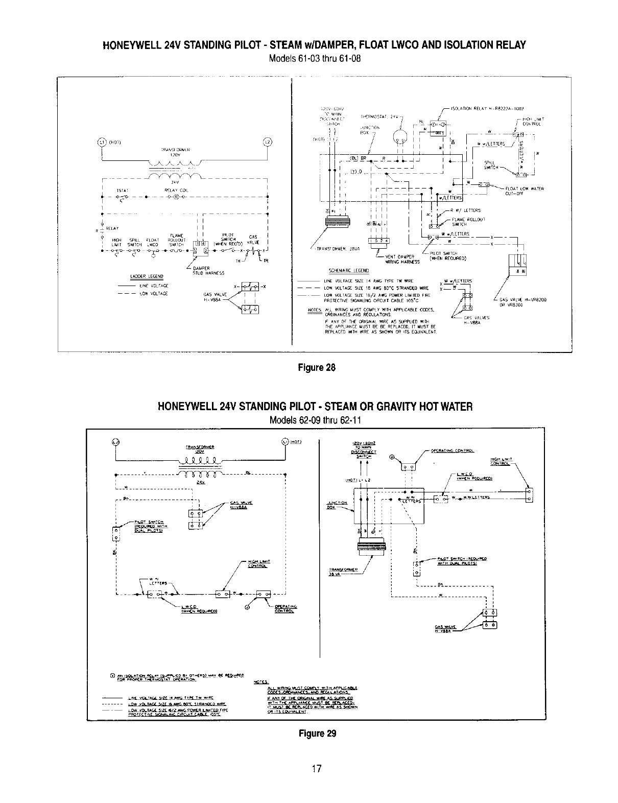
HONEYWELL 24V STANDING PILOT -STEAM w/DAMPER, FLOAT LWCO AND ISOLATION RELAY
Models61-03thru61-08
2_v 7
I
TST_ _LA¥ COIL
I F
_ ml I
R _ RELAY II I
_ADC,CR LEr_ND
LINE VOLTAGE
LO_ VOLTAGE
_TUB _AP,NES$
X_ _X
H V88_
Figure28
HONEYWELL 24V STANDING PILOT -STEAM OR GRAVITY HOTWATER
Models62-09thru 62-11
/r_'f_
Figure29
17

HONEYWELL SPARK IGNITION (HSP) - GRAVITY OR STEAM w/DAMPER, FLOATLWCO AND ISOLATION RELAY
Models61-03thru61-07
-- ?
TRANSFORME_
120V
_J_J_J
I
TSTAI F_ELA_" COIL
_R L I I SpARK
IAODER tECENO
:IN_ VOLTAGE
_OW VOL_SE
ilrl
Figure30
HONEYWELL SPARK IGNITION (HSP) -FORCED HOTWATER w/DAMPER
Models61-03thru 61-07
4_OJTJL_
Z4_
'/?v"
......... _ : _ -4,
_)_ ..........................._t _. _ ,, _l_._ _L,._J _. ..........
,i i i
_ _ ,
_/_ , ,
• w
i i ii i1_ !
Figure31
18

HONEYWELL SPARK IGNITION (HSP) - FORCED HOTWATER w/COIL AND DAMPER
Models61-03thru61-07
_--_ ..... _-rr'ccc_..... _'-.... -
I
i....
L............ _w...... L I i _I
....
_---= __=__-_2
-- L_IN__,rAG_ _tt 14 _rY_ TW
........ IC_ _ SiZE 16 _ BO'C STA,*I,_O W,RI_
I@_ -* ..... , ............
* 1
@
L...... __'..iJ__J z-__.,qt_ •
, i
•_x- __+J
Figure32
HONEYWELL SPARK IGNITION (HSP-2) - GRAVITY OR STEAM w/DAMPER, FLOATLWCO AND ISOLATIONRELAY
Model61-08only
OPERAnNG CO_IFtOL O_
120V_60HZ r_ERUOS_I ISOLAtiON_[tAY H-RB222A IC,0_
TRANSFORMER
.... <.o.<t!, ; • ....
ILOW WAEP, Cu_-Orr
_ L ME _3LtC_JT
I I I COt_TFIO_S
_'_ _ _ _lii ' 1
SmEi HARNESS_ Il I Z: i %\ flING HIN SS ui FILO:_RNER _, I C_BL_ _ I , , _BL_ A
_RC_ D roif i_ x 7039 _ i _ II PILOT BURN[R
--.......... _ppkor GAS._ L _LO_ iigAIN LOW VI_IA_ "Z[ 15 A" "C51R_D£D "R<.............. L_.,_,, R _-- _--1-- -- --J_'
-- LINE VOtTACE VAL',_
VAL ,,_,_5 V;*L_ H VRll_<14
¢OL .... LOW VOLT,_Gt"SIZE 16/'2 A_ POll UkilErl FIRE
pROIE_TI_ _I_JNALqN__II!_ULT ¢_E IflS'C
_ROUND LEAEitI4N_IZ_ If Al_f__<1" C SIRAN_I] II_ll[
MORES ALL _4111N8HUST CC_4mty141H I_PLIOABLE _(:(YES 0RDINAN_[_ #*bid RECNLAllI:_t5
In ANY I Ill( ilCINAL _I4N[AS _PPU[I_ li4]H [HE _P_IANg[ MU_T
BE FIEPL#*CE_IT IdUST I_ REPLACED 1,41H11411[A_ _H_)l_ldt ITS EQUIVALENI
Figure33
19
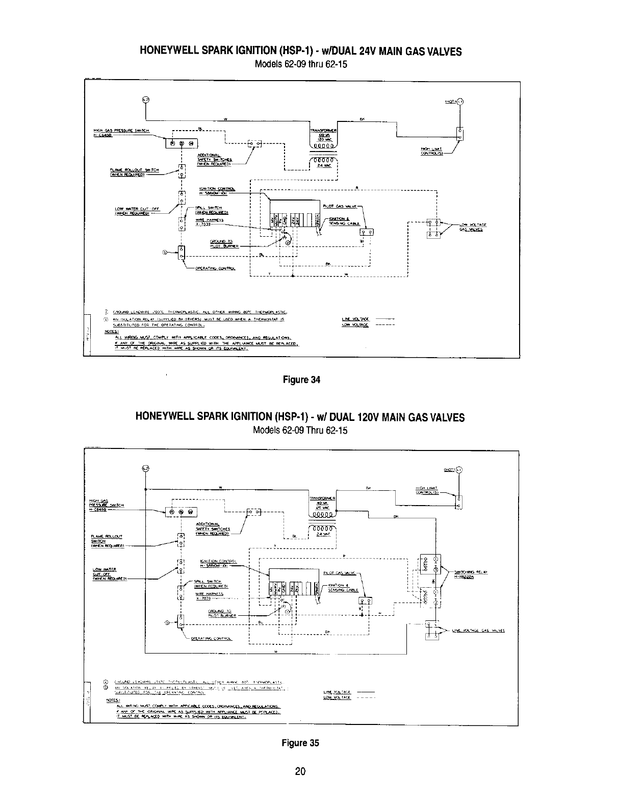
HONEYWELL SPARK IGNITION (HSP-1) - w/DUAL 24V MAIN GAS VALVES
Models62-09thru 62-15
_j m
1[................
i i ;
i i
_,L W_ _ _,V___ _T_ _ICA_[ COOlS. C,_O_',_ES. A_ _1'_ A_IC,_S,
Figure34
HONEYWELL SPARK IGNITION (HSP-1) -w/DUAL 120V MAIN GAS VALVES
Models62-09Thru62-15
........"F
............ [ '! ....... "
_ _, _D ,_ ,¢_,_ ._=_.p_,x _L_._. *,.,_ _0_ T_pL_;T _
NOTES=
=
Figure35
2O
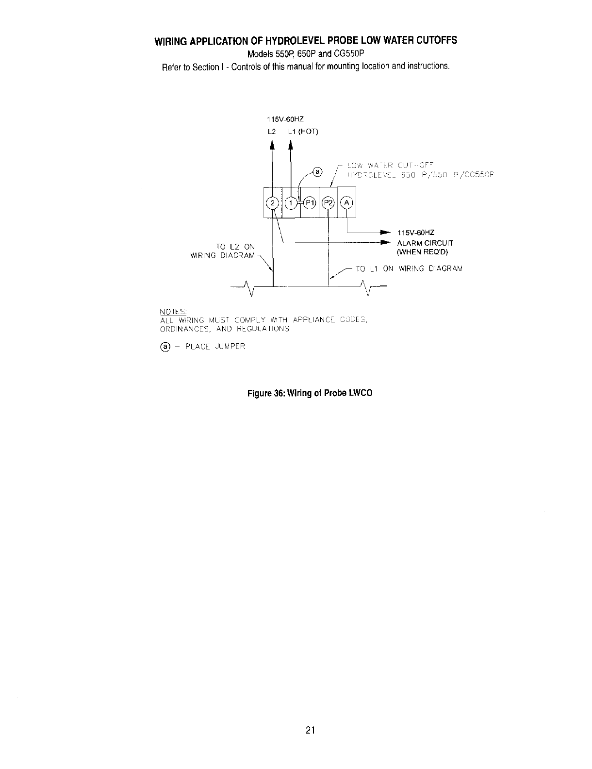
WIRING APPLICATION OF HYDROLEVEL PROBE LOW WATERCUTOFFS
Models550P,650PandCG550P
Referto SectionI - Controlsof this manualfor mountinglocationandinstructions.
115V-60HZ
L2 L1 (HOT)
£
L
TO L2 ON
WIRING DIAGRAM _,
--I1_- 115V-60HZ
ALARM CIRCUIT
(WHEN REQ'D)
sTO L1 ON WIRING DIAGRAM
NOTES:
ALL WIRING MUST COMPLY W!TH APPLIANCE CCDE3,
ORDINANCES, AND REGULATIONS
(_) PLACE JUMPER
Figure 36:Wiringof ProbeLWCO
21
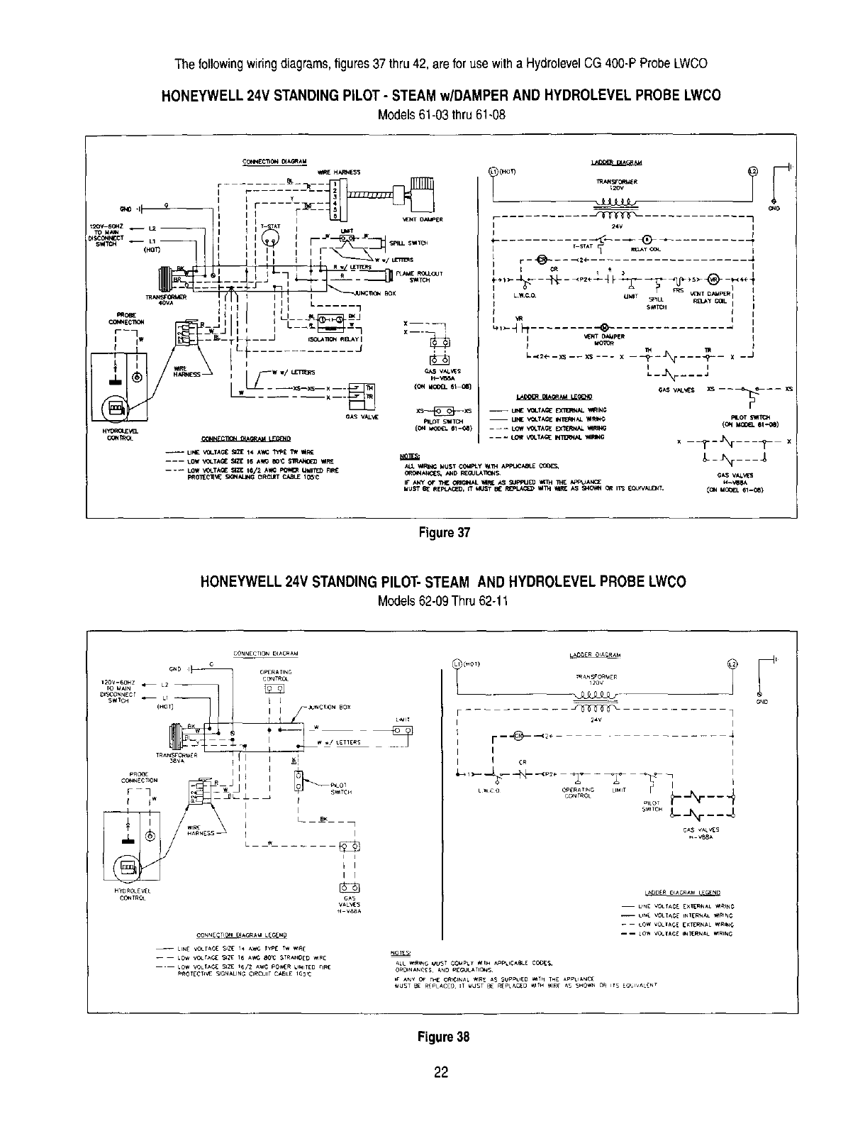
The followingwiringdiagrams,figures37thru 42, arefor use witha HydrolevelCG400-PProbeLWCO
HONEYWELL 24V STANDING PILOT- STEAM w/DAMPER AND HYDROLEVEL PROBE LWCO
Models61-03thru61-08
_SCON_J_T
S_TC _ -- L1
(HO
mANSF_
4OVA
PROBE
_E C_I_t -- -
r],
-- UN£ ",_.TA_ Sa21E14 AW_ _TW tF, E
-- __ LOw t@-T_ NIl 1_/2 A_4_ _UMI11_ RF_
C_,INEC_ _A_AU
_H_ESS
r F R
I:F _¢ _ _kL S_
I
I I I I r--
Ix---_
I
L/_, ,
i___w w/ _ _ vat.s
----,=-_-- _<Zz_r_ 1 ion._o___ =1
CAS VAL_ _S---_-_XS
(ol+i i_ 61-0_)
ALL I_IRING MUST COMPly _n_ APP',JOm_
IF" ANy OF _O_dG_NALI_R_ AS _JPPU_ _ _ P4_PI_AN_E
MUST _REPtJ_C_O, IT 141JST BE R_PLl_ll_ _l113t llIRE AS SitO_I_4OR I/'3 _CAJIVALD_T.
/
RLOT metC_
-_---%---_- x
_-_N____
Figure37
HONEYWELL 24V STANDING PILOT-STEAM AND HYDROLEVEL PROBE LWCO
Models62-09Thru62-11
HYO_OLEV_L
CO_TRC_
CONNECTION DIAGRAU LEC,_NO
-- UN£ vo_r,_c_ _Z_ i,, _,wc WP[ _w ,_
LOW VO_IAC_ _zt _/2 ,_w_; pO_R UMIT[D rIFle
_OTE¢_V_ _ON_.LING ¢l_tCulr CABLE IO_:
I I
I I
V88_
I I
I I cR
L_co OP_R,_T_G LIMIT
CONTROL
L
F ....... J_ ]
I r--'@-_+ ....
I
I
.....
..... __N___ 4
G_S VALES
V88A
LADDER OAGIIAW G NB
U_E V0LrAG£ EXI[R_AL '_I_ING
GND
Figure38
22
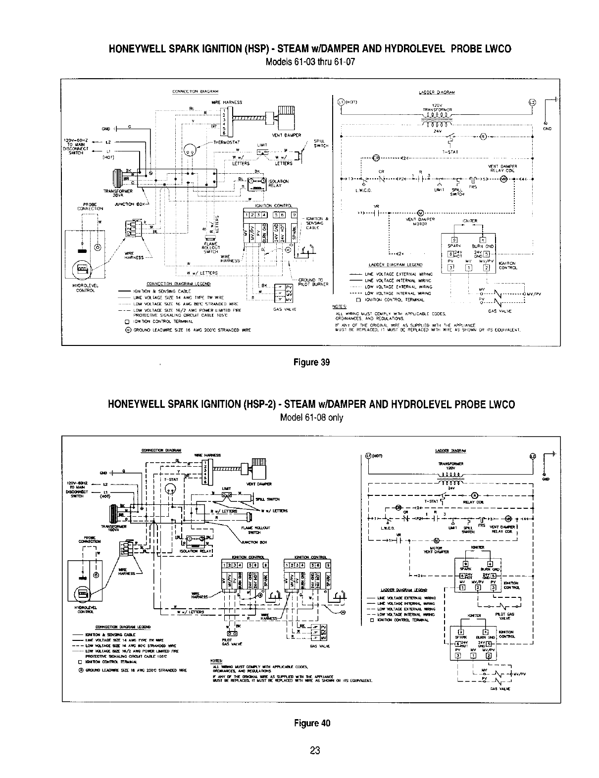
HONEYWELL SPARK IGNITION (HSP) - STEAM w/DAMPER AND HYDROLEVEL PROBE LWCO
Models61-03thru61-07
CO_EClrO_ I_AGRAM
MRE HARNESS
! i i]ilZSS]
............ _1 . T,E,.O_,,T L....... I_,%
TRAN_C_M( R "l _
*,OVA
HY'OROLEVEL CONNECTION =ACRa_ LEGE_ ! )WBK _ P_LOT BURN[r
mI¢_IIlON k _,_N_NG CABLE
LOW VOLI'_CE _ZE _6 _,WG aO_ STRa_C_D V4RE
---- LOW VOLIACE _ZE 16/2 AWG pO_'_ERLIM_TEO nRE G*_S vaU_
PROECnVE SIgnALING CIK'CUIt CABLE 105_3
OI_1_O N COnTr.. lgR_IN;*L
_) CROdND LE^0_E SIZE t6 AWC _00',3 _TRAND_D 'MI_E
T_N_FORME _
24V
/
•_,,---,_---.1_........ ;g Fo _ ,_ "p....... @.......
<_ _rRS
LW¢O u_m_ _LL
,m
...... _F: ......... ® ....................................
: VEN] _AMpE_? IGNIIE R
-- UN_ VOL;ACE INERNAL _IRING
UV
..... LOW_IDL_CE INT_RNA L _4RING :O=..=J_t _ .V/F=V
ALL _NG MUST COMPLY _ APPUCA_E CODEg G_ V_LVE
ORDNANCES AND _[_UL_T_OnS
rr AN_ OF THE oN6mNAL _E AS _PPLIED _'_TH THE A_IANCE
_USJ 8( r_EpLA¢£D tT _lUgT _ RfPL_Cf_ _TH WIRE AS SHO_IN OR FTS [oUWAI_NT
Figure39
HONEYWELL SPARK IGNITION (HSP-2) -STEAM w/DAMPER AND HYDROLEVEL PROBE LWCO
Model61-08only
PROT_CTNES_ O_O_t C_t£ I_
-fir
,,
Ii*-n m"_ m_ __
I[' "%
e_s v,_u_
r..--- ¢[
i
v_v_
_o_
Figure40
23
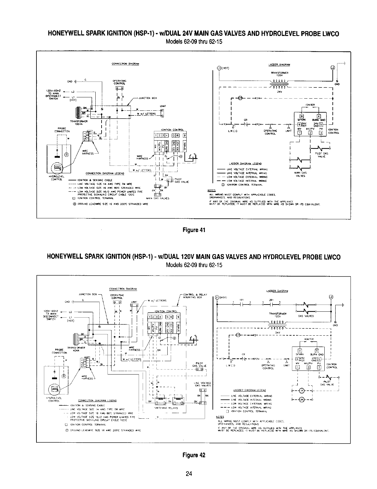
HONEYWELL SPARK IGNITION (HSP-1) -w/DUAL 24V MAIN GAS VALVESAND HYDROLEVEL PROBE LWCO
Models62-09thru62-15
............Ti(HOt)
IRANsrO_E_
_OV
_J3LLLt_ o,o
_'Iv i
I I
....
VAL_
-- LING VOtT;_C[ EXT_F_N_L_e,NG
Figure41
HONEYWELL SPARK IGNITION (HSP-1) -w/DUAL 120V MAIN GAS VALVES AND HYDROLEVEL PROBE LWCO
Models62-09thru62-15
CONNCC_ON DIACP,_U
rIIIC0_NECT _i I I I
v• _ f I
.+,1 /_ \\ m ;j
- ' _ iiP_-- G_S VALVES
HYr)NOLfV[L I t _
,,,..<,.,°%,,.,,y,,,,_,:,.,?,,,o,< ,..... W _-_ ]
ION'T'ON CONISOL I_P,'_INAL
_) GRoUNO LEAOIRE _ll{ 16 J_ 200C STRANDED IRE
(H°T) IRI 2RI 2_
T_AN_'0l_ ER
_V I
r_ ___.,._ .......
iIC'WITER I
;t :.- _ --_ - .<p2e
-- pr_A _'_T _V _V/PV PV icN_o_
_wco OG _G LMIT _C (
III
,,
| |
-- LING VOLTAGE E_IERNAL ,_RINe _I-- _
_C2_5
Figure42
24

BOILERSEQUIPPEDWITHCONSTANTBURNINGPILOT
HONEYWELL GAS VALVELIGHTING INSTRUCTIONS
NOTE:CHECKWATERLINEOFSTEAMBOILER,ORBECERTAINSYSTEMISFULL
FORWATERBOILER,BEFOREPROCEEDINGWITHTHESEINSTRUCTIONS.
FOR YOUR SAFETY READ BEFORE LIGHTING
WARNING: If you do not follow these instructions exactly, a fire or explosion may result
causing property damage, personal injury, or loss of life.
A, This appliance has a pilot whichmust be lighted by hand.When
lighting thepilot, follow these instructions exactly.
B. BEFORE OPERATINGsmell all around theappliance area for
gas. Be sure to smell next to the floor because some gas is
heavier thanair and will settleon the floor.
WHATTO DO IFYOU SMELL GAS
• Do not try to light any appliance.
e Do not touch any electric switch; do not use any phone in
your building.
• Immediately call your gas supplier from a neighbor's phone.
Followthe gas supplier's instructions.
C,
D,
• Ifyou cannot reachyour gas supplier,callthe fire department.
Use only your hand to push in or turn the gas control knob.
Never use tools. If the knob will not push in or turn by hand,
don't try to repair it, call a qualified service technician.Force or
attempted repair mayresult in a fireor explosion,
Do not usethis applianceif any part hasbeenunderwater.
Immediatelycall a qualifiedservicetechnicianto inspectthe
applianceandtoreplaceanypartofthecontrolsystemandany
gascontrolwhichhasbeenunderwater.
LIGHTING INSTRUCTIONS
1. STOP! Read the safety information aboveon this page.
2. Set the thermostat to lowest setting.
3. Turn off all electric power to the appliance.
4. If the gas valve is not visible, removecontrol access panel.
5. If the gas control knobis not inthe "OFF" position,turn the knob
clockwise _ to"OFF."
6. Wait five (5) minutesto clear out any gas. Then smell for gas,
including near the floor. If you then smell gas, STOP! Follow"B*
in the safety information above on this page. If you don't smell
gas, go to the nextstep.
7. Removethe pilotaccess panel, if supplied, located below and
behind the gas valve directly above burner tubes.
10.Pushinredresetbuttonallthewayandholdin.Immediatelylight
the pilotwitha match.Continueto holdthe resetbuttonin for
aboutone(1) minuteafterthe pilotis lit.Releasebuttonandit
will popbackup,Pilot shouldremainlit. If it goesout,repeat
steps5 through10.
• If buttondoesnot pop upwhenreleased,stopand immedi-
atelycallyourservicetechnicianorgassupplier.
• If the pilot will not stay lit after severaltries, turn the gas
controlknobto "OFFandcallyourservicetechnicianor gas
supplier.
11.Replacepilotaccesspanel,if applicable.
12.Turnthegascontrolknobcounterclockwise_ to=ON."
13.Replacecontrolaccesspanel,ifapplicable.
8. Find pilot followmetaltube from gas valve.The pilot is
betweentwoburnertubes.
9. Turnthegascontrolknobcounterclockwise_ to "PILOT"
14.Turnonallelectricpowerto theappliance.
15.Setthe thermostatto desiredsetting.
S_E _Ew
Ga* Cont,_l Knob
(-_n ,,_"OFF" Rtd Reset 8ulto*
P°""') _ S
tNL[T
TO TURN OFF GAS TO APPLIANCE
1. Set the thermostat to lowest setting. 4. Turn the gas control knob clockwise _ to "OFE"
2. Turnoff all electric power to the applianceif service is to be per-
formed. 5. Replace control access panel,if applicable.
3. If the gas valve is not visible, removecontrol access panel.
25

BOILERS EQUIPPED WITH ELECTRIC IGNITION AND A COMBINATION GAS VALVE
OPERATING INSTRUCTIONS
NOTE:CHECKWATERLINEOFSTEAMBOILER,OR BE CERTAINSYSTEMIS FULL
FORWATERBOILER,BEFOREPROCEEDINGWITHTHESEINSTRUCTIONS.
FOR YOUR SAFETY READ BEFORE OPERATING
WARNING: If you do not follow these instructions exactly, a fire or explosion may result
causing property damage, personal injury, or loss of life.
A. This appliance is equipped with an ignitiondevice which auto-
matically lights the pilot. Do not try to light the pilot by hand.
B. BEFORE OPERATINGsmell all around the appliance area for
gas. Be sure to smell next to the floor because some gas is
heavier than air and will settle on the floor.
WHATTO DO IFYOU SMELL GAS
•Do not try to light anyappliance.
•Do not touch any electric switch; do not use any phone in
your building.
•Immediately call your gas supplier from a neighbor's phone.
Followthe gas supplier's instructions.
C.
D,
• If you cannotreachyour gassupplier,call thefire department.
Useonly yourhandto pushin or turn the gas controlknob.
Neveruse tools.Ifthe knobwill not pushin orturn by hand,
don'ttryto repairit,callaqualifiedservicetechnician.Forceor
attemptedrepairmayresultina fireor explosion.
Do not use this applianceif anypart has beenunderwater.
Immediatelycall a qualifiedservicetechnicianto inspectthe
applianceandto replaceanypartof thecontrolsystemandany
gascontrolwhichhasbeenunderwater.
OPERATING INSTRUCTIONS
1.STOP!Readthe safetyinformationaboveonthispage.
2. Setthethermostatto lowestsetting.
3. Turnoffallelectricpowertothe appliance.
7.Waitfive (5)minutesto clearoutany gas.Thensmellfor gas,
includingnearthe floor.If you smellgas,STOP!Follow=B"in
thesafetyinformationaboveonthispage.Ifyoudon'tsmellgas,
gotothe nextstep,
4. This appliance is equippedwith an ignitiondevice which auto-
matically lights the pilot.De not try to light the pilotby hand.
5. If the gas valve is not visible, removecontrol access panel.
6. Ifthe gas control knobis not inthe "OFF position, turn the knob
dcokwise f-4 to "OFF"
8.Turnthegascontrolknobcounterclockwise_ to"ON."
9. Replacecontrolaccesspanel,if applicable,
10.Turnonallelectricpowerto the appliance.
11.Setthethermostatto desiredsetting.
12.If theappliancewill notoperate,followtheinstructions"ToTurn
Off GasTo Appliance"andcall yourservicetechnicianor gas
supplier.
H_H VOLTAC,_
Gas Conlrol Knob
position)_
6A5
INLIT
TO TURN OFF GAS TO APPLIANCE
1. Set the thermostatto lowest setting. 4. Turnthe gascontrolknobclockwise F-4 to "OFF:'
2. Turn off all electricpowerto the appliance if service is to be per-
formed. 5. Replacecontrol access panel, if applicable.
3. If the gas valve is not visible, remove control access panel.
26
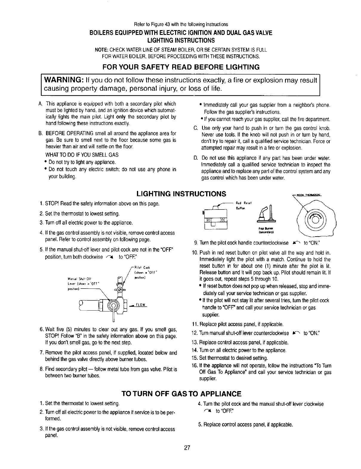
Referto Figure43withthefollowinginstructions
BOILERS EQUIPPED WITH ELECTRIC IGNITION AND DUAL GAS VALVE
LIGHTING INSTRUCTIONS
NOTE:CHECKWATERLINEOF STEAMBOILER,OR BE CERTAINSYSTEMIS FULL
FORWATERBOILER,BEFOREPROCEEDINGWITHTHESEINSTRUCTIONS.
FOR YOUR SAFETY READ BEFORE LIGHTING
WARNING: If you do not follow these instructions exactly, a fire or explosion may result
causing property damage, personal injury, or loss of life.
A. This appliance is equipped with both a secondary pilot which
must be lighted by hand, and an ignition devicewhich automat-
ically lights the main pilot. Light only the secondary pilot by
handfollowingthese instructionsexactly.
B. BEFOREOPERATINGsmell all around the appliance area for
gas. Be sure to smell next to the floor because some gas is
heavierthan air and will settle on the floor.
WHATTO DO IFYOU SMELL GAS
• Do not try to light anyappliance.
• Do not touch any electric switch; do not use any phone in
yourbuilding.
C.
B.
•Immediatelycall your gas supplier from a neighbor's phone,
Followthe gas supplier'sinstructions.
• If you cannot reachyour gas supplier,call thefire department,
Useonlyyour handto pushin orturn the gas controlknob.
Neverusetools.If the knobwill notpush in or turn by hand,
don'ttryto repairit,calla qualifiedservicetechnician.Forceor
attemptedrepairmayresultinafire orexplosion.
Do not usethis applianceif any part has beenunderwater.
Immediatelycall a qualifiedservicetechnicianto inspectthe
applianceandto replaceanypartofthecontrolsystemandany
gascontrolwhichhasbeenunderwater.
LIGHTING INSTRUCTIONS
1.STOP!Readthesafetyinformationaboveonthispage.
2. Setthethermostatto lowestsetting.
3. Turnoffallelectricpowerto theappliance.
4. Ifthe gascontrolassemblyis notvisible,removecontrolaccess
panel.Referto controlassemblyonfollowingpage.
5. If themanualshut-offleverandpilotcockarenotinthe "OFF"
position,turnbothclockwise_-4 to"OFF."
Pil©_ Cock
{ 5how_in "ofF*
Man_al S_tu_- 0ll _osd_on)
Lever (s_o,n ;, -o[r-
6. Wait five (5) minutes to clear out any gas. If you smell gas,
STOP! Follow"B"in the safety informationabove on this page.
Ifyou don'tsmell gas, goto the nextstep.
7. Removethe pilotaccesspanel,if supplied,locatedbelowand
behindthegasvalvedirectlyaboveburnertubes.
8. Findsecondarypilot-- followmetaltubefromgasvalve.Pilotis
betweentwoburnertubes.
R**d Rese+
Svff_,
9. Turnthepilotcockhandlecounterclockwise_ to"ON."
10.Pushin redresetbuttonon pilotvalveall the wayandholdin.
Immediatelylight the pilot witha match.Continueto holdthe
resetbuttonin for aboutone (1) minuteafterthe pilot is lit.
Releasebuttonandit will popbackup.Pilotshouldremainlit.If
it goesout,repeatsteps5through10.
• If resetbuttondoesnotpopupwhenreleased,stopandimme-
diatelycallyourservicetechnicianor gassupplier.
• Ifthepilotwillnotstaylit afterseveraltries,turnthe pilotcock
handleto "OFF"andcallyourservicetechnicianorgas
supplier.
11.Replacepilotaccesspanel,if applicable.
12.Turnrnanualshut-offlevercountercleckwise_ to"ON."
13.Replacecontrolaccesspanel,if applicable.
14.Turnonallelectricpowerto theappliance.
15.Setthermostatto desiredsetting.
16.Iftheappliancewi[Inotoperate,followthe instructions"ToTurn
Off GasTo Appliance"andcall yourservicetechnicianor gas
supplier.
TO TURN OFF GAS TO APPLIANCE
1. Set the thermostat to lowest setting.
2. Turnoff all electric power to the applianceif service is to be per-
formed.
3. If thegascontrolassemblyis notvisible,removecontrolaccess
panel.
4. Turnthe pilot cock and the manual shut-off lever clockwise
to "OFF
5. Replacecontrolaccesspanel,ifapplicable.
27

SIAqK IGNITED pILOT _STO. PILOT
IGNITI
BLEED TUBING
--VENT TO 118*q BLEED TU6E OR TO OUTSIDE
ATMOSPHERE WELL /M3OVE NORMAL _REATHING
LEVEL AS APPLICABLE
PILOT GAS VALVE
I/4" TEST
PILOT
pILOT COCK
MANUAL S:_UT -OFF
VALVE
E_ _THERMOCOUPLE
LEAD
IGNITION CONTROL
BO_
LEFT SIOC JACKET PANEL
Figure43: HSPControlSystemandIgnitionControlBoxLocation
Models62-09thru 62-15
28

Referto Figure44withthefollowinginstructions
BOILERS EQUIPPED WITH ELECTRIC IGNITION AND A COMBINATION GAS VALVE
OPERATING INSTRUCTIONS
NOTE:CHECKWATERLINEOF STEAMBOILER,OR BE CERTAINSYSTEMIS FULL
FORWATERBOILER,BEFOREPROCEEDINGWITHTHESEINSTRUCTIONS.
FOR YOUR SAFETY READ BEFORE OPERATING
WARNING: If you do not follow these instructions exactly, afire or explosion may result
causing property damage, personal injury, or loss of life.
A. Thisapplianceis equippedwithanignitiondevicewhichauto-
maticallylightsthepilots.Donot fryto lightthepilotsby hand.
B. BEFOREOPERATINGsmellallaroundthe applianceareafor
gas.Be sureto smellnextto the floorbecausesomegas is
heavierthanairandwill settleonthe floor.
WHATTODOIFYOUSMELLGAS
•Donottryto lightanyappliance.
• Donottouchanyelectricswitch;donotuseanyphonein
yourbuilding.
• Immediatelycallyour gassupplierfroma neighbor'sphone.
Followthegassupplier'sinstructions.
• Ifyoucannotreachyourgassupplier,callthefiredepartment.
C.
D,
Use only your hand to push in or turn the gas control knob.
Never use tools. If the knob will not push in or turn by hand,
don't try to repair it, call a qualified service technician.Force or
attempted repair may result in a fire or explosion.
Do not use thisapplianceif any part hasbeenunderwater.
Immediatelycall a qualifiedservicetechnicianto inspectthe
applianceandto replaceanypartof thecontrolsystemandany
gascontrolwhichhasbeenunderwater.
OPERATING INSTRUCTIONS
1. STOP! Readthe safety informationabove on this page. 7. Wait five (5) minutes to clear out any gas. Then smell for gas,
2. Setthethermostatto lowestsetting.
3. Turnoffallelectricpowerto theappliance.
4. Thisapplianceis equippedwithan ignitiondevicewhichauto-
maticallylightsthepilots.Donot tryto lightthepilotsbyhand.
5. If the gas valveis not visible,removecontrolaccesspanel.
Referto controlassemblyonfollowingpage.
6. If thegascontrolknobandpilotcockarenotinthe"OFF"
position,turnbothclockwise_ to "OFF."
includingnear the floor. Ifyou smell gas, STOP!Follow"B" inthe
safety informationabove on this page. If you don't smell gas,go
to the nextstep.
8. Turnthe gas control knob and pitotcock counterclockwise
to "ON."
9. Replace controlaccess panel, if applicable.
10.Turn on all electric power to the appliance.
11. Set the thermostat to desired setting.
,,,,,c,,, 12. If the appliance willnot operate, follow lhe instructions "ToTurn
"""'°'" Off Gas To Appliance" and call your service technician or gas
Gas Control Knob ............ o.- supplier.
(shownin "OFF ....... --_
TO TURN OFF GAS TO APPLIANCE
t. Setthethermostattolowestsetting. 4. Turnthegascontrolknobandpilotcockclockwise_-4
2.Turnoffallelectricpowertotheapplianceifserviceistobeper- to"OFF."
formed.
3. Ifthegasvalveisnotvisible,removecontrolaccesspanel. 5. Replacecontrolaccesspanel,ifapplicable.
29

SpAR_ IGNkTEO PLLOT
_N GAS VALVE
\\\\\\
_ lLO__T _ VALVE
PILOT COCK
Figure44:HSP-2 ControlSystem
Model61-08
30

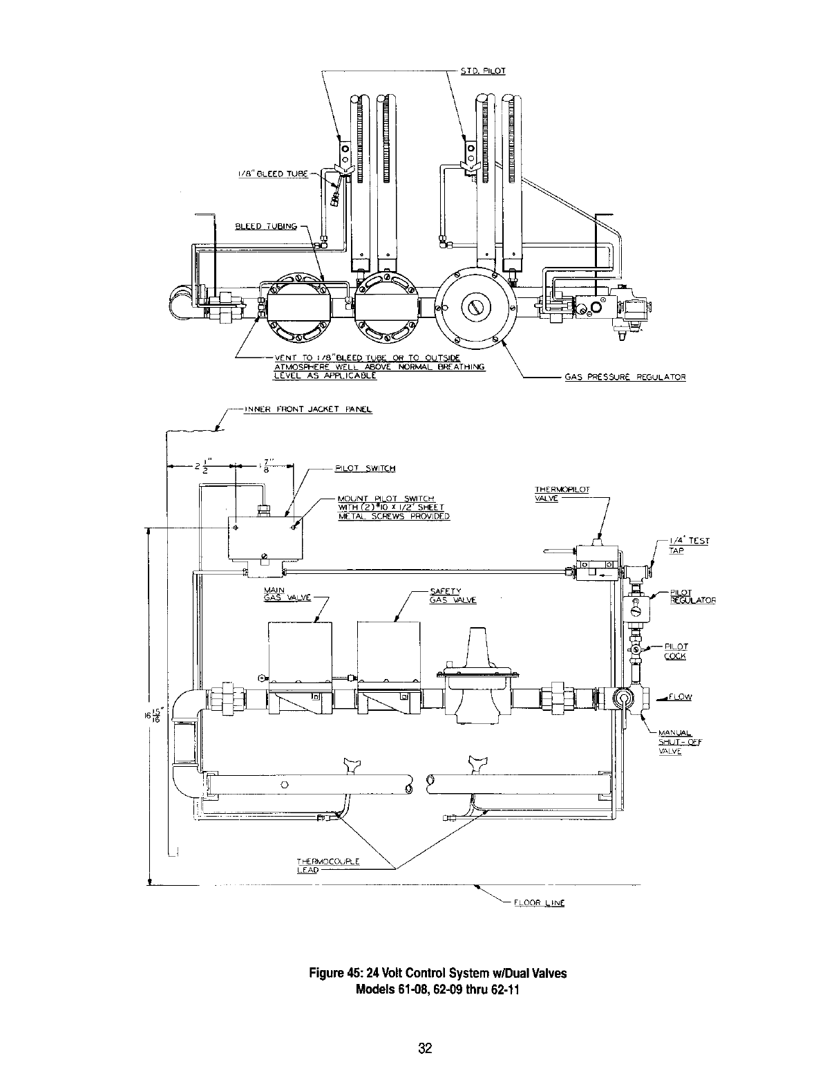
Referto Figure45withthefollowinginstructions
BOILERS EQUIPPED WITH CONSTANT BURNING PILOT(S)
LIGHTING INSTRUCTIONS
NOTE:CHECKWATERLINEOFSTEAMBOILER,ORBECERTAINSYSTEMIS FULL
FORWATERBOILER,BEFOREPROCEEDINGWITHTHESEINSTRUCTIONS.
FOR YOUR SAFETY READ BEFORE LIGHTING
WARNING: If you do not follow these instructions exactly, a fire or explosion may result
causing property damage, personal injury, or loss of life.
A. This appliance has pilots which must be lighted by hand.When
lighting the pilots, follow these instructions exactly.
B. BEFORE OPERATINGsmel_all around the appliance area for
gas. Be sure to smell next to the floor because some gas is
heavierthan air and will settleon the floor.
WHATTO DO IFYOU SMELL GAS
•Do not try to light any appliance.
• Do not touch any electric switch; do not use any phone in
your building.
• Immediately call your gas supplier from a neighbor's phone.
Followthe gas supplier's instructions.
C.
D,
• Ifyoucannotreachyourgassupplier,callthefiredepartment.
Use only your hand to push in or turn the gas control knob.
Never use tools. If the knob will not push in or turn by hand,
don't try to repair it, call a qualifiedservice technician. Forceor
attempted repair may result in a fire or explosion.
Do not use thisapplianceif any part has beenunderwater.
Immediatelycall a qualifiedservicetechnicianto inspectthe
applianceandto replaceanypartofthecontrolsystemandany
gascontrolwhichhasbeenunderwater.
LIGHTING INSTRUCTIONS
1. STOP!Read the safety informationabove on thispage.
2. Setthe thermostat to lowest setting.
3. Turn off all electric power to the appliance.
4. If the gas control assemblyis not visible, removecontrolaccess
panel,
5. g the manualshut-off lever and pilot cock are not in the "OFF"
position,turnbothe,ockwiseto"OFF" ,o'o
posi_ion)_
6.Wait five (5) minutes to clear out any gas. If Nu smell gas,
includingnear the floor. If you smell gas, STOP!Follow"B"in the
safety informationaboveon this page.If you don't smell gas, go
to the next step.
Vah_
9. Turnthe pilot cockhandle counterclockwise _ to "ON."
10. Push inred reset buttonon right hand pilot valve all theway and
hold in. Immediately light the right hand pilot with a match.
Continueto holdthe resetbutton in forabout one (1)minuteafter
the pilot is lit. Release button and it will pop back up, Pilot
should remain lit. If it goes out, repeat steps 5 through10.
11. Repeatabovelightingprocedurewith lefthandpilotvalveand
lefthandpilot.
• Ifeitherbuttondoesnotpopupwhenreleased,stopand
immediatelycallyourservicetechnicianor gassupplier.
• Ifthepilotswill notstaylitafterseveraltries,turnthepilot
cockhandleto "OFF"andcallyourservicetechnicianor
gassupplier.
12. Replace pilot access panel, if applicable.
7. Removethe pilot accesspanel,if supplied,locatedbelowand
behindthegasvalvedirectlyaboveburnertubes.
8. Findpilots-- followmetaltubefromeachpilotvalve.Eachpilot
isbetweentwoburnertubes.
13.
14.
15.
16.
Turnmanual shut-off levercountercloekwise _ to"ON."
Replace controlaccess panel,if applicable.
Turnon all electric power to the appliance.
Set thermostat to desired setting.
TO TURN OFF GAS TO APPLIANCE
1, Set the thermostat to lowest setting.
2. Turnoff all electric power to the appliance ifservice is to be per-
formed.
3. Ifthegascontrolassemblyisnotvisible,removecontrolaccess
panel.
4. Turn the pilot cockand the manual shut-off leverclockwise
to"OFF."
5. Replace control accesspanel, ifapplicable.
31
I/8"BLEED
GAS PI_ESSURE REGULATOR
_/_INNER FRONT J,t*CKET PANEL
16_"
i,, 7,,
_2 2 _8 F_LOT
- THERMC_ILOT
I/4" TEST
TAP
MAIN SAFETY _ ]'F_- P_
T PERMOCOUPLE
FLOO R LINE
Figure45:24 VoltControlSystemw/DualValves
Models61-08,62-09thru 62-11
32

0- INSTRUCTIONS FOR OPERATION
1--The installationisnot completeuntil Ratingand LightingPlatesareon the boilerandthe"UsersInformationManual"and "Installation
Instructions"are hung neartheboiler
2--System shouldbe maintainedin good repair.Radiators,baseboardunitsand/orconvectorsmustbe keptclean.
:_lf a radiatordoes notheat allover.air hasprobablyaccumulatedandshouldbe vented.
P- CHECKOUTPROCEDURE
1--After startingboiler,becertainall controlsare workingproperlybeforeleavingit unattended,Checkto be sure thatthe temperaturelimitcontrol
will shut offthe boilerin theeventof excessivetemperature,by loweringlimitset pointuntil mainburnersshutdown,Returnlimitto desiredset
point.
2_heck gas tightnessof maingas valvewhenclosedto be certainthereis no leakageto theburners.Checkall joints periodicallyfor gas
teakage.Usesoapsolutionto check leakage.
3_heck the operationof the ignitionsystemsafetyshut-offdeviceusingthefollowingmethod:
a. ConstantBurningPilot:With thegas cock knobin the pilotposition,extinguishpilot flameand makecertainthe gasvalveshutsoff gasflow
to thepilot withintwo (2) minutes,Torelight follow"LightingInstructions".
b. SparkIgnitionSystems:Withthe unitoperating,turn off thegasat the inletshut-offvalveupstreamfromtheboiler.The unitwill spark
attemptto relight.If pilot lock-outisprovided,thespark willstopwithin ninety(90)seconds,To relightfollow"OperatingInstructions".
Q-SHUT-DOWN CAUSED BY PILOT OUTAGE, VENT SAFETY SHUT OFF SWITCH OR FLAME ROLL-OUT SAFETY SHUT OFF
SWITCH
1--1nthe eventof a shut-downcausedby a pilotoutage,actionof the ventsafetyshutoffswitchorflame roll-outsafetyshut-offswitcheffectinga
shut-downof themain burners:
a. Turnoff all electricpowerto the boiler.
b. Referto "Lightingor OperatingInstructions"andturn gascock knobto "off" position.
c. Call a qualifiedheatingserviceorganizationor localgascompanyand havethe causeof the shut-downinvestigatedand corrected.
d. Referto "Lightingor OperatingInstructions"to re-startboiler.
-NOTE:-
SHOULDOVERHEATINGOCCURORTHE GASSUPPLYFAILTO SHUTOFF,DONOTTURNOFFORDISCONNECTTHE ELECTRICAL
SUPPLYTOTHEPUMP,INSTEAD,SHUTOFFTHE GASSUPPLYATA LOCATIONEXTERNALTOTHEAPPLIANCE.
DO NOTUSETHISAPPLIANCEIFANY PARTHASBEENUNDERWATER,IMMEDIATELYCALLA QUALIFIEDSERVICETECHNICIANTO
INSPECTTHEBOILERANDTOREPLACEANY PARTOFTHECONTROLSYSTEMANDANY GAS CONTROLWHICHAS BEENUNDER
WATER.
33

Cleaning the Series 61162Steam Boiler with Skim Tapping
Thefollowingcleaningprocedureshallbe performedbyaqualifiedserviceperson.
1. Cleantheboileras describedbelownolaterthanoneweekaftertheinitialstart up,Cleaningwillbe moreeffectiveiftheboileroperatesa day
ortwoto loosensedimentand impuritiesinthesystem.
2, Theboiler mustbe cleanedto removeanyaccumulatior_ofoil, grease,sludge,etc.thatmaybeinthesystem,Thesesubstancescancause
foamingand surgingof the boilerwater,producingan unstablewaterline andwatercarryoverto thesystem,
WARNING:CLEANINGTHEBOILERREQUIRESTHEUSEOFVERY HOTWATERANDCORROSIVECHEMICALS.USECAREWHEN
HANDLINGTO PREVENTiNJURY.
3. Connecta 11/2"pipe nippleand shutoff valveto skim tapping.
4. Connecta 11/2"drain lineoff of the skimvalve,runto a pointof safedischarge.
5. Closeall valvesto the system.Providea meansof continuousfresh waterto theboilerfor the cleaningprocess.
6. Openthe skimvalve.Fill the boiler untilwaterbeginsto flow outof the valve.Shutoff fill valve.
7. Usecommonwashingsoda(suchas Arm and HammerSuperWashingSoda).Mixthesoda withwaterin a 10quartpailand pourintothe
boilerthroughthe safetyvalvetapping.Mixa proportionof one(1) poundof washingsodafor each800squarefeetEDRnet boilerrating.
CAUTION:DO NOTLEAVETHEBOILERUNATFENDEDWHILEFIRING.TAKEGREATCARENOTTO ALLOWTHEWATERLEVELTO
DROPBELOWTHEBOT[OM OFTHE GAUGEGLASSORTOALLOWFRESHWATERMAKEUPTO FLOWINTOOFAST.THISWILLAVOID
THE POSSIBILITYOFCAUSINGTHEBOILERSECTIONSTO FRACTURE.
8. Turn burnerson and allowthe boilerwaterto heat up to just below steaming(180 to 200degreesF). Cyclethe burnersto maintaintemperature
duringskimming.Do notallowthe boiler to steam.Steamingmixesup thecontaminantsinthe waterinsteadof floatingthemat the surface.
9. Openthemake-upwatervalveto continuouslyfeed waterto the boiler.Allowwaterto flow outof theskimtapping.
10. Continueskimmingthe boileruntilthe waterflowingfromthe skimtappingflowsclear.Thiswill takesometime,possiblyseveralhoursfora dirty
system.
11, After skimmingis complete,closethe skimvalveandturn off the boiler.
12. Closethe make-upwatervalveandopen theboilerdrain valve.
13. Draintheboiler completely.Refillanddrain againoneor two timesto makesure allof the sodahas beenwashedout.
14. Restorepipingto normal.Pipea nippleand capin theskim valve.
15. Note: If the gaugeglass becomesdirtyagain,this indicatesmorecontaminantshaveworkedloosein thesystem.Repeatthe cleaningand
skimmingprocessas neededto cleanthe system.
34

R - RATINGS,TAPPINGLOCATIONSAND DIMENSIONALDATA
SERIES 61 ,7_,E,,
'D" 2SUPPLY lAPPING I "F'
. o
1_ INLET_ "" 5" _ R
_,_"A"_ _' B' _ Lz_'
LEFT SIDE FRONT RIGHT SIDE
Location
[
L
M
N
O
P
Q
R
S
SizeN.RT.
3/4,,
1/2,,
1/2"
2"
3/4"
3/4"
1112.
3/4.
112"
SERIES 61 TAPPING LOCATIONS
Steam
PressureGauge"
N/A
GaugeGlassand RoarLowWaterCut-Off
Return
SecondaryProbe LowWaterCut-Off
SafetyValve
Skim Tapping
PrimaryProbeLowWaterCut-Off
GaugeGlassforPrimaryProbeLWCO
Water
LimitControl
Theraltimeter
N/A
Return
N/A
ReliefValve
N/A
N/A
N/A
*MountGauge using 3/4' nipple,couple and 3/4" X 1/4" bushingwhena float lowwate cut-offis used.
SERIES 61 BOILER RATINGS
i DOE
HeatingCapacity WaterContent
MBH' Net I=B=RRatings_Gallons
Boiler
Model Input
Number MBH Water Steam
90 73 72
120 98 97
160 130 129
200 161 161
240 193 193
280 225 225
Steam Steam2Wate#
Sq.Ft. MBH MBH
225 54 63
304 73 85
404 97 113
504 121 140
604 145 168
704 169 196
61o03
61-04
61-05
61-06
61-07
61-08
SparkIgn,w/Damper i
SeasonalEfficiency
(AFUE)'
Water Steam Water
80.5 80.6 8,16
81.7 80.7 10.32
81.3 80.6 12.48
81.0 80.6 14.64
80.6 80.6 16.80
80.3 80.6 18.96
Steam
4,80
5.88
6.96
8.04
9.12
10.20
Boiler
Model Width
Number "A"
61-03 143/4"
61-04 18T/8"
61-05 23"
61-06 27V8"
61-07 31V4"
61-08 353/8"
Jacket
Depth
"B"
i 27V4"
271/4"
27V4"
27v4"
27V4"
30V4"
Topto
Floor
"C"
35"
35"
35"
85"
35"
35"
SERIES 61 BOILER DIMENSIONS
Rightof Rear of
Jacket Jacket
to ctlof to ctlor Flue
Flue Flue Size
"D.... E.... F"
73/B" 39/16" 5"
97/16,, 41116' ' 5"
11_/2" 49/16" 6"
139h6,'49h6" 7"
15518" 6VIe" 8"
17"he" 61h6" 8"
Distance
Between
Tappings
"G"
131_"
171A"
213_"
25V2"
295/_'
Flueto
Chimney
Diameter
5 _
5 _
6"
7 _
8"
8"
Chimney
Size
5"x 20'
5" x20'
6" x20'
7" x20'
8"x 20'
8"x 20'
1 Net I=B=Rwater ratingsbased on an allowanceof 1.15.
2 Net I-B--R steam ratingsbased on an allowanceof 1.333.
3 Consultfactorybeforeselectinga boiler forinstallationshaving unusualpipingandpickuprequirements,suchas interm_ent system
operation,extensivepiping systems,etc.
4 HeatingCapacityandAnnual FuelUtilizationEfficiency(AFUE)ratingsare basedon U.S.Governmenttest,Beforepurchasingthis
appliance,read importantinformationabout its estimatedannualenergyconsumptionsor energyefficiencyratingthat is availablefrom
your retailer.
35

R - RATINGS,TAPPINGLOCATIONSAND DIMENSIONALDATA
SERIES 62
N_ ÷
FLOOR LINE_I-LI_4!
LEFT SIDE
,,mr,
35"
"DI.... [ ,, 17_"E"
"G" 2 7
#'G'" TL,_ Fr
/
/ ,,/ I_LET_ _ .5' 'kff_ r_
I I VALVE 161_ _ ,_ _b_ -|
J
_'A'_' _ BI,, _ LYe'
FRONT RIGHT SIDE
Location
I
J
K
L
M
N
O
P
Q
R
S
SizeN.RT.
3/4.
3/4.
3/4"
1/2"
1/2"
2"
3/4-
3/4"
11/2"
3/4-
1/2"
SERIES 62 TAPPING LOCATIONS
Steam
PressureGauge*
N/A
N/A
N/A
Gauge Glass and FloatLow WaterCut-Off
Return
SecondaryProbeLowWaterCut-off
SafetyValve
SkimTapping
PrimaryProbe LowWaterCut-off
GaugeGlass for PrimaryProbe LWCO
"PressureGauge, Operatingand LimitControlon Models12-15
Water
LimitControl/Models09-11)
OperatingControl(Models12-16)
LimitControl(Models12-15)
Theraltimeter
N/A
Return
N/A
ReliefValve
N/A
N/A
N/A
Boiler
Model Input
Number MBH
62-09 320.0
62-10 360.0
62-11 400.0
62-12 440.0
62-13 480.0
62-14 520.0
62-15 560,0
I=B=R
GrossOutput
MBH
Water Steam
256 256
288 288
320 320
352 352
384 384
416 416
448 446
SERIES62 BOILERRATINGS
Net I=B=R
Ratings
Steam Steam Water
Sq.Ft, MBH MBH
800 192 223
900 216 250
1000 240 278
1100 264 306
1200 288 334
1309 312 362
1400 336 390
Combustion
Efficiency
Water Steam
80.0 80.0
80.0 80.0
80.0 80.0
80.0 80.0
80.0 80.0
80.0 80.0
80.0 80.0
i
Water
21.12
23.18
25.34
j27.60
J 29.66
i3182
j 3398
Water
Content
Gallons
Steam
11.28
12.36
13.44
14.52
15.60
16.68
17#6
Boger
Model
Number
62-09
62-10
62-11
62-12
62-13
62-14
62-15
Width
uA-
39V2"
435/8"
4713/16"
52"
561/8"
605h6"
647/1s"
Jacket
Depth
"B"
301/4"
30114"
301h"
301/4"
30V4"
30V4"
30V4"
Topto
SERGES62 BOILER DIMENSIONS
Rightof Rearof Flue
Jacket Distance Jacket Size
to c/I of Betw.Tw¢ to cffof "F"
Floor Flue
"C" "D"
35" t4"
35" 15"
35" 16"
35" 18"
35" 19"
35" 20'h6"
35" 22Ve"
Distance
Between
Flea c/l'e Rue (Each Tappings
"D1.... E" of 2) "G"
119h6" 49/16" 6" 33314"
1311116" 49/1e" 7" 37_/e"
15_3h6" 49116" 7" 42V16"
151She" 6V16" 8" 46V4"
18V_e" 6V_6" 8" 50316"
20_he" 6V_6" 8" 549h6"
203/16" 61116" 6" 5811116"
Distance
Betw.Rt.
Sup.&Tap. Flueto
Inter. Chimney Chimney
"Gt" Diameter Size
N/A 9" 9" x 20'
N/A 9" 9" x 20'
N/A 9" 9" x 20'
21V_6" 10" 10" x20'
253h6" 10" 10" x 20'
253h6" 10" 10"x20'
295h6" I0" I0" x20'
36

S - MAINTENANCE AND INSPECTION
1--This boilermustbe disconnectedfromthe gas supplypipingduringanypressuretestingof thesystem.RefertoSectionH - "GAS PIPING".
Note8 for details.
2--The gasventusedonthis boi{erisofthe horizontalto verticaltype.Thevent andventingsystemshouldbeinspectedthoroughlyat the
beginningof eachheatingsystem.
3--The areawherethe boileriscontainedshould beclearand free fromcombustiblematerials,gasolineandotherflammablevaporsand liquids.
The boilerarea shouldhaveample air for combustionandventilationand thereshouldbe no obstructionspreventinga free flow of air
4--AI1low watercut-offsshouldbetested and inspectedper manufacturer'sinstructions,any floattypesshouldbeflushed ona weeklybasisto
removeanysedimentfromthefloat bowl.
5--A visualcheck of burnerandpilot flameshouldbe conductedat least oncea year.Theflame interconeshouldbeapproximately11/2inches
high andshouldhavea very sharp,bfuecolorcharacteristic.SeeFigurebelow.
m w
f
f
/\
/\
\/
\ J
f
6--At the beginningofeach heatingseason,fluewaysandburnersshouldbecheckedforcleanlinessand cleanedifnecessary.Followingprocedure
wouldapplyif cleaningis required.
a. Turnoft allelectricalpowerto boilerbeforebeginningcleaningoperation.FollowLighting/OperatingInstructionsfor shuttingoff
maingas to appliance.
b. Removetheflue pipe,drafthood,top jacketpanelsand flue collector.
c. Brushfluewayswithwirebrush.
d. Replaceflue collector.Whenreplacingthe flue collector,be certainthat the sealingropebetweenthe fluecollectorandtop section
makesa tight seal to preventleakageof the productsof combustion.
e. Replacethetop of jacket,draft hoodand flue pipe.
f. Removethejacketclean-outcover plate.See Figure4.
g. Removecast ironcover plateby removingfour (4)cap screwsat thecornersof theplate.
h. Brushtubeswith wire brush.
i. Replacecoverplates.MakesureHi Tempropegasketis in place.
j. Removefrontjacketpanel (Figure4), and burneraccesscoverdoor (Figure11).
k. Removeburnersandbrushgasoutletports lightlyusingsoft bristlebrush.
I. Replaceburners(SeeFigure12)and alljacket panels.
m. FollowLighting/OperatingInstructionsforputtingboilerinto operation.
37

REPAIR PARTS
SERIES 61/62 GAS BOILERS
REPAIR PARTS ARE AVAILABLEFROM YOUR INSTALLER OR BY CONTACTING
PEERLESS HEATER COMPANY,BOYERTOWN,PA 19512-0855
NOTE: REMEMBER TO INCLUDE BOILER MODEL NUMBER AND SERIAL NUMBER WHEN ORDERING PARTS.
Item No. Description AdditionalInformation
tIntermediateSection
2 Left HandEndSection
3RightHandEndSection
4
5
6
7
8
9
10
11
12
13
14
15
16
17
18
19
20
21
22
23
24
25
26
27
28
Part No.
P-150
P-151
P-152
P-152C
P-154
12-EF
64
P-162
P-161
P-158
P-120
P-106
X-1037
X-1023
X-1034
P-155
P-156
X-1009
X-1001
P-4208
P-4209
P-4210
X-4003
X-3005
P-503
P-504
TappedIntermediateSection
Push Nipple
Push Nipple
5/8"HighTemperatureRope
CompleteBlockAssembly
LeftHandBlockAssembly
RightHandBlockAssembly
DrawRodsw/nutsandwashers
Clean Out CoverPlate
1/4"HighTemperatureRope
TanklessHeaterFlangew/screws
RubberGasket
CoverPlatew/screws
BaseBack
BaseBack
Draw-UpWasher
Draw-UpWasher
3/4"Gas Manifold
1" Gas Manifold
11/4"Gas Manifoldfor 62-15
OrificeSpud
Steel Burnerw/pilot bracket
Steel Burner
ThrottlingPilot Cock
FlueCollector
DraftHood
50 lb.WorkingPressure
50 lb.WorkingPressure
w/CoilOpening
w/Cast ClosedCoil Opening
50 lb.WorkingPressure
1 RequiredPerFlueway
1 RequiredPerFlueway
42" RequiredPerFlueway
SpecifyBoilerModel
SpecifyBoilerModel
SpecifyBoilerModel
SpecifyBoilerModel
44"RequiredFor P-106
SpecifyBoilerModel
SpecifyBoilerModeland Rightor Left Side
2 Required
2 Required
SpecifyBoilerModel
SpecifyBoilerModel
SpecifyQuantify,Typeof Gas,BoilerModelandAltitude
SpecifyControlSystem
SpecifyQuantity
Specify BoilerModel
Specify BoilerModel
38

Item No, Part No. Description
29 JacketAssembly
TheraltimeterGauge
SteamGauge
Gauge GlassBet
3/4"DrainCock
LightingInstructionPlate
Lighting/OperatingInstructionsLabel
HighTemperatureSealingCement
1/2"Pint Can NippleSealer
1/4"AluminumTubing
WaterTrim
SteamTrimw/LWCO
GasValve
Pilot
IgnitionControl
LimitControl
Gas ControlAssembly
AdditionalInformation
Specify BoilerModel
SpecifyControlSystem
SpecifyControlSystem
SpecifyQuantityof Containers
SpecifyQuantity
Specify Quantityin Feet
SpecifyBoilerModel,ControlSystem,Typeof Gas
SpecifyControlSystemandTypeof Gas
SpecifyModel
SpecifyBoilerModelandControlSystem
SpecifyControlSystem
39
Series 61/62
Gas Boilers
Installation,
Operation Et
Maintenance
Manual
TO THE INSTALLER:
This manual is the property of the owner and must
be affixed near the boiler for future reference.
TO THE OWNER:
This boiler should be inspected annually by a
Qualified Service Agency.
HI Division ASME
af gama
PEERLESS BOILERS
www.peerless-heater.com
@2003 Peerless Heater Company P8207 R23 (3/03-2,5M)
Printed in U.SA.
