PEERLESS Boiler Manual L0308196
User Manual: PEERLESS PEERLESS Boiler Manual PEERLESS Boiler Owner's Manual, PEERLESS Boiler installation guides
Open the PDF directly: View PDF ![]() .
.
Page Count: 17
WBV/WV
Boilers
Installation,
Operation
Maintenance
Manual
PEERLESS"
CAST IRON BOILERS

Packaged or Knockdo ,
8 Sizes 3-5 Sections .60 to 2.00 GPH Input 82% to 86% AFUE
Natural Draft (chimney) Venting
Factory Assembled Sections on Knockdown Boilers
•Reduces Installation Time
WBV in 3 and 4 Section for Hot Water or Steam
• Convertible from Rear to Top Flue for Venting Flexibility
WV in 5 Section for Hot Water
• Top Flue Only
High Efficiency Flame Retention Burners
• Choice ofBeckett, Carlin or Riello
Full Plate Swing-Out Door
• Standard on All Boilers
•Provides Easy Access to Combustion Chamber Area
jbr Cleaning and Servicing
Large Water Content, Wet Base Section Design
• Reduces On/O_'f'Cycling
Steel Push Nipples
• Provide a Permanent Water Tight Seal Between Sections
• Unaffected by Petroleum and Other Contaminants
Deluxe Insulated Enameled Steel Jacket
• Reduces Boiler Heat Loss
Safety Controls
• Prob_ or Floai Type Low Water
Cut-Qff Approved on Steam Boilers
Tankless Coils
• For Domestic Hot Water Production
on Hot Water Boilers
As an ENERGY STAR _ Partner Peerless Healer Comparl¥ Has delerr#med
that certain f_rin9 rales of this product mee_ Ihe ENERGY STAR" guidelines
for energy efficiency
• Honeywell Operating Controls
• Taco 007 Circulator on Packaged Water Boilers
• Probe Type LWCO on Packaged Steam Boilers
omp\e te J • Tankless Coils
• Barometric Draft Damper
• Grundfos Circulator on Packaged Water Boilers
• Float Tltpe LWCO on Packaged Steam Boilers
/'_'<'rl(,._.s 1 lec_ttq Compony is p&_a.s_d lo q[]_'r otlt _@the" most coml)reh_.t_siv¢" u,tu_c_ttty l)i-o()l(lms ill
the. hlHztstry. All P(x'rless tz!sidential cckst iron boilers i11chtde a.fidl orl(! !F.ar It,azTcUlty. A limiled.
li]_'litllt" It,(tt r(iNly is provided jbr Ihe cc_st iron sections q[ Pcerless rt_sidetltial hol [t,(llt_!t boilet_.
P_'_tl('._5 _tl._o i)tol,id<!s o linlit_'d. 11!11_](fOf [tl_UTO/l/t] Oil I_l(_C€ISt irotl SeCtiotls Q[ il5 I'('si_lt,llllol sl(?at]l
boil_'t._. Fit,(, ariel !('n !j('cw _5\'l_!lld('d [t,olv_lltli('s oil parts €Old lclbor nre IIOIL! (Ip(lilflblt'. P[('_Is_' COllStll/
]_'('rl_'y;5 [ It'(tlt,r ('OmlXUl!lJbr compIt'lt" tt,(ltT_ttll[I il!fbrmation.
PEGRLESS _
CAST IRON BOILERS
Peerless Heater Company * 231 North Walnut Street •Boyertown, PA 19512-1021 * 610-367-2153 •www.peerless-heater.com
FAB WBV RI (5!02 5M)
prlrlf(?(l _rl U S A
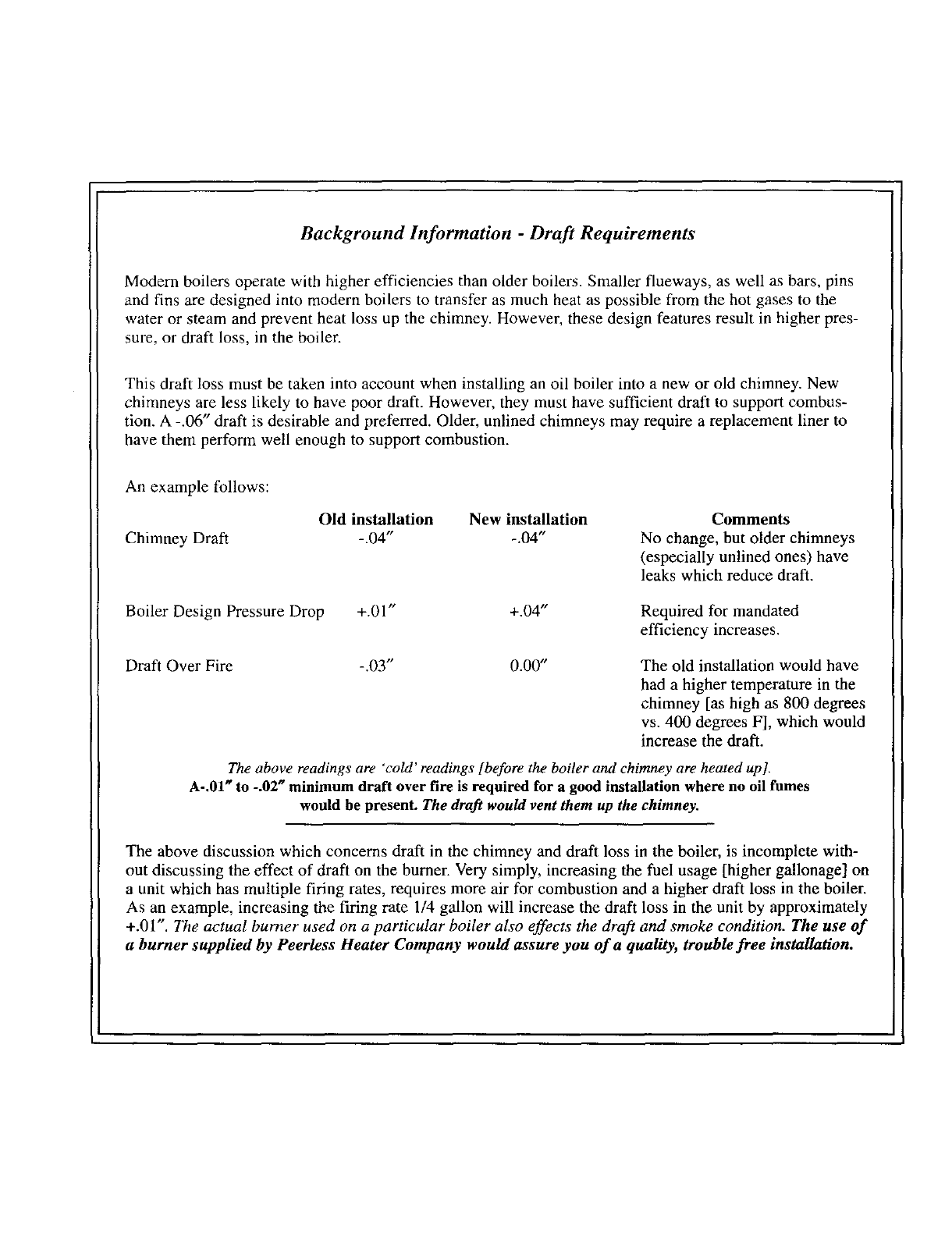
Background Information -Draft Requirements
Modern boilers operate with higher efficiencies than older boilers. Smaller flueways, as well as bars, pins
and fins are designed into modern boilers to transfer as much heat as possible from the hot gases to the
water or steam and prevent heat loss up the chimney. However, these design features result in higher pres-
sure, or draft loss, in the boiler.
This draft loss must be taken into account when installing an oil boiler into a new or old chimney. New
chimneys are less likely to have poor draft. However, they must have sufficient draft to support combus-
tion. A -.06" draft is desirable and preferred. Older, unlined chimneys may require a replacement liner to
have them perform well enough to support combustion.
An example follows:
Chimney Draft
Old installation New installation
-.04" -.04 °Comments
No change, but older chimneys
(especially unlined ones) have
leaks which reduce draft.
Boiler Design Pressure Drop +.01" +.04" Required for mandated
efficiency increases.
Draft Over Fire -.03" 0.00" The old installation would have
had a higher temperature in the
chimney [as high as 800 degrees
vs. 400 degrees F], which would
increase the draft.
The above readings are 'cold' readings [before the boiler and chimney are heated up].
A-.01 _to -.02 _minimum draft over fire is required for a good installation where no oil fumes
would be present. The draft would vent them up the chimney.
The above discussion which concerns draft in the chimney and draft loss in the boiler, is incomplete with-
out discussing the effect of draft on the burner. Very simply, increasing the fuel usage [higher gallonage] on
a unit which has multiple firing rates, requires more air for combustion and a higher draft loss in the boiler.
As an example, increasing the firing rate 1/4 gallon will increase the draft loss in the unit by approximately
+.01". The actual burner used on a particular boiler also effects the draft and smoke condition. The use of
a burner supplied by Peerless Heater Company would assure you of a quality, trouble free installation.
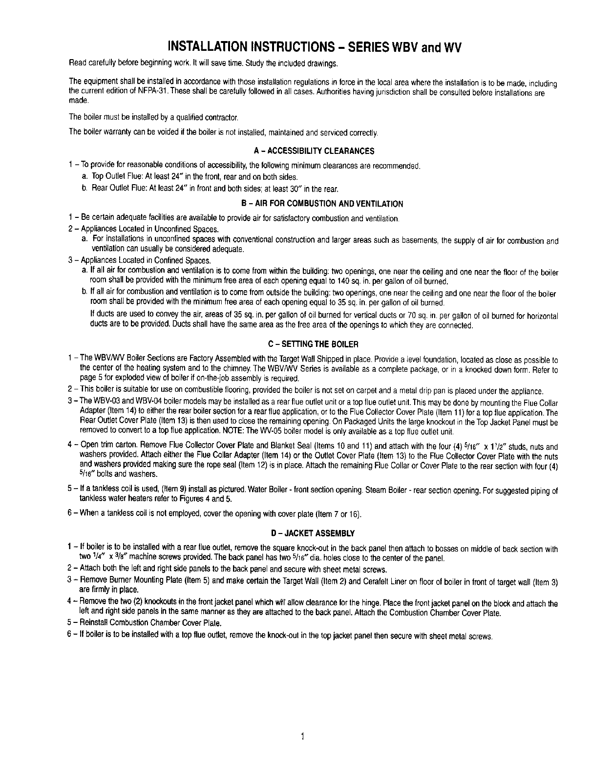
INSTALLATIONINSTRUCTIONS-SERIESWBV andWV
Readcarefullybefore beginningwork.It willsavetime.Studytheincludeddrawings.
Theequipmentshall beinstalledinaccordancewiththoseinstallationregulationsin forceinthe localareawherethe installationis to bemade,including
the currenteditionof NFPA-31.Theseshall becarefullyfollowedinall cases.Authoritieshavingjurisdictionshall beconsultedbeforeinstallationsare
made.
Theboiler mustbe installedby a qualifiedcontractor.
The boiler warrantycanbe voidedifthe boileris notinstalled,maintainedandservicedcorrectly.
A-ACCESSIBILITYCLEARANCES
1 - Toprovidefor reasonableconditionsof accessibility,thefollowingminimumclearancesare recommended.
a. TopOutletFlue:At least24" in thefront,rear andon bothsides.
b. RearOutletFlue:At least24" infrontand bothsides;at least30" inthe rear.
B-AIRFORCOMBUSTIONAND VENTILATION
1-Be certainadequatefacilitiesare availableto provideairfor satisfactorycombustionand ventilation.
2 -Appliances Locatedin UnconfinedSpaces.
a. Forinstallationsin unconfinedspaceswith conventionalconstructionand larger areassuchas basements,the supplyof airfor combustionand
ventilationcan usuallybe consideredadequate.
3 - AppliancesLocatedin ConfinedSpaces.
a. If all air for combustionandventilationis to come fromwithinthe building:two openings,one nearthe ceilingand one nearthe floor ofthe boiler
roomshallbe providedwiththe minimumfree area of eachopeningequalto 140sq. in. pergallonof oil burned.
b. If allair for combustionandventilationis to comefromoutsidethe building:twoopenings,onenearthe ceilingandone nearthefloor ofthe boiler
roomshall beprovidedwith the minimumfreeareaof eachopeningequalto 35 sq.in. per gallonof oil burned.
If ductsare usedto conveythe air,areasof 35 sq. in.per gallon of oil burned for verticalductsor 70 sq.in. per gallonof oil burnedfor horizontal
ductsare to be provided.Ductsshallhavethesame area asthe free areaof theopeningsto whichtheyare connected.
C-SETTINGTHE BOILER
1-The WBV/WVBoilerSectionsare FactoryAssembledwiththeTargetWallShippedinplace.Providea levelfoundation,locatedas close as possibleto
the center of the heatingsystemand to the chimney.The WBV/WVSeries is availableas a completepackage,or in a knockeddownform. Referto
page5 for explodedviewof boilerif on-the-jobassemblyisrequired.
2 -This boileris suitablefor use on combustibleflooring,providedtheboiler is not set on carpetand a metal drippan is placedunderthe appliance.
3 - TheWBV-03andWBV-04boilermodelsmaybe installedas a rearflue outletunit ora topflue outletunit.This maybedone bymountingthe FlueCollar
Adapter(Item14)to eithertherear boilersectionfora rearflueapplication,orto the FlueCollectorCoverPlate(Item11)fora topflue application.The
RearOutletCoverPlate(Item13) is thenusedto closetheremainingopening.On PackagedUnitsthe largeknockoutinthe TopJacketPanelmustbe
removedto convertto a top flue application.NOTE:The WV-05boiler modelis only availableas a top flueoutlet unit.
4-Open trim carton.RemoveFlueCollectorCoverPlateand BlanketSeal(Items10 and 11) and attachwith thefour (4) 5/16" x 1_/2"studs,nutsand
washersprovided.Attacheitherthe FlueCollar Adapter(Item14) or the OutletCoverPlate(Item 13)to the Flue CollectorCover Platewiththe nuts
and washersprovidedmakingsurethe ropeseal (Item12)is in place.Attachthe remainingFlueCollar or CoverPlateto the rearsectionwithfour (4)
5/r6" boltsandwashers.
5-If atanklesscoilis used,(Item9)installas pictured.WaterBoiler- frontsectionopening.SteamBoiler- rearsectionopening.Forsuggestedpipingof
tanklesswater heatersreferto Figures4 and 5.
6 - Whena tanklesscoil is notemployed,covertheopeningwithcoverplate(Item 7 or 16).
D-JACKETASSEMBLY
1- If boiler is tobe installedwitha rear flueoutlet,removethesquareknock-outin the backpanelthen attach to bosseson middleof back sectionwith
two 1/4" x 3/8"machinescrewsprovided.The backpanelhas two 5/16"dia.holescloseto the centerof the panel.
2 - Attach boththe left and rightside panelsto the backpanel andsecure withsheet metalscrews.
3 - RemoveBurnerMountingPlate (Item5) andmake certainthe TargetWall (Item2) and CerafeltLiner on floor of boiler in front oftarget wall (Item3)
arefirmly in place.
4 - Removethe two(2)knockoutsinthefrontjacketpanelwhichwill allowclearanceforthe hinge.Placethefrontjacketpanelonthe blockandattachthe
left and rightside panelsin the samemanneras theyare attachedto theback panel.Attachthe CombustionChamberCoverPlate.
5 - ReinstallCombustionChamberCoverPlate.
6 - If boiler isto be installedwitha top flueoutlet, removetheknock-outinthe topjacket panelthen securewith sheetmetalscrews.
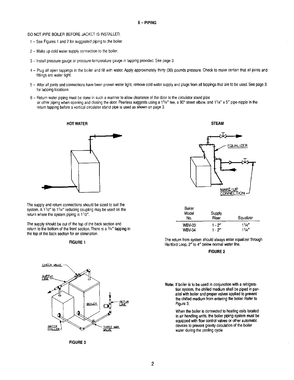
E - PIPING
DONOTPIPEBOILERBEFOREJACKET_SINSTALLED.
1- See Figures1 and2 forsuggestedpipingto the boiler.
2-Makeup cold watersupplyconnectionto the boiler.
3 - Installpressuregaugeor pressure-temperaturegaugein tappingprovided.See page3.
4-Plugal_opentappingsin the boilerand fill with water.Applyapproximatelythirty (30) poundspressure.Checkto make certainthat all ioints and
fittingsare watertight.
5 - After alljoints andconnectionshavebeen provenwatertight,removeooldwatersupplyand plugsfromall tappingsthatare to be used,Seepage3
for tappinglocations.
6 - Returnwater pipingmustbe donein such a mannerto allowelearaooeof the door to the circulatorstandpipe
orother pipingwhenopeningand closingthedoor.Peerlesssuggestsusinga 11/4"tee, a 90° streetelbow,and 11/4"x 5" pipenippleinthe
returntappingbeforea verticalcirculatorstandpipeis usedas shownon page3.
HOTWATER
v
Thesupplyand returnconnectionsshouldbe sizedto suitthe
system.A 1r/2" to 11/4" reducingcouplingmaybe usedon the
returnwherethe systempipingis 11/2".
Thesupplyshouldbe outof thetop of the backsectionand
returnto thebottomof the front section.There is a 3/4"tappingin
the top of thebacksectionfor airelimination,
FIGURE1
STEAM
Boiler
Model Supply
No. Riser Equalizer
WBV-.03 1 - 2" 11/4"
WBV-04 1- 2" 11/4"
Thereturnfromsystemshouldalwaysenterequalizerthrough
HartfordLoop,2" to 4" belownormalwater line,
RGURE2
_TER
FIGURE3
Note:If boileris to be usedinconjunctionwitha refrigera-
tionsystem,the chilledmediumshallbepipedin par-
allelwithboiler andpropervalvesappliedto prevent
thechimedmediumfromenteringtheboiler.Referto
Figure3.
Whentheboiler isconnectedto heatingcoilslocated
inairhandlingun_S,the boilerpipingsystemmustbe
equippedwithflowcontrolvalvesor otherautomatic
devicesto preventgravitycirculationof theboiler
waterduringthe coolingcycle.
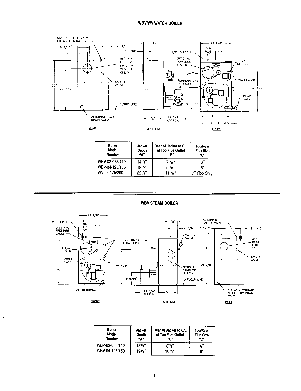
WBV/WVWATERBOILER
SAFETY RELIEF VALVE
.35" VALVE
DRAIN VALVe"
--2 11/16"
31/16" _
• 6" REAR
FLUE "C"
_(WBV-O3,
WBV-04
ONLY)
LINE
R_
1
1 I/2" SUPPLY_
OPTIONAL
TANKLESS
HEATER x
LIMIT -
TEMPERATURE
PRESSURE
GAUGE _'
1_3/_ I_-
APPROX '
-_-_2,18"7
1 114"
' "C'"DOLATO"
28 I/2"
DRAIN
VALVE
FRONT
Boiler Jacket Rearof JackettoC/L Top/Rear
Model Depth ofTopFlueOutlet FleaSize
Number "A.... B.... C"
WBV-03-085/110 141/8" 71h6" 6"
WBV-04-1251150 18%" 91h6" 6"
WV-05-175/200 22%" 111116" 7" (TopOnly)
WBV STEAMBOILER
SKIM
PROBE
FLOAT LWCO
[
ALTERNATE
29 7/8"
_OP_ONAL
TANKLESS J
HEATER
-FLOOR LINE
_2 11/16"
_6"
_REAR
FLUE
-C-
'_SAFETY
VALVE
1 I/4" ALTERNATE
RETURN OR DRAIN
VAL'AE.
g_
Boiler
Model
Number
Jacket Rear of Jacketto C/L Top/Rear
Depth of Tap Flea Outlet Flue Size
"A.... B" "C"
WBV-03-085/110 153/4" 87/8" 6"
WBV-04-125/150 19314" 10%" 6"
3
HIGH TEMPERATURE
HOT
MIXED
MIN.
WATER
MIXER
HEATER
V4" CONTROl_
"TAPPING
CONTROL
HIC.H TCMPCRATUR_"
HEATER
i2 _ MiN°
3/4" CONTROL
FLOW
INLET
COLD WATER
INLET
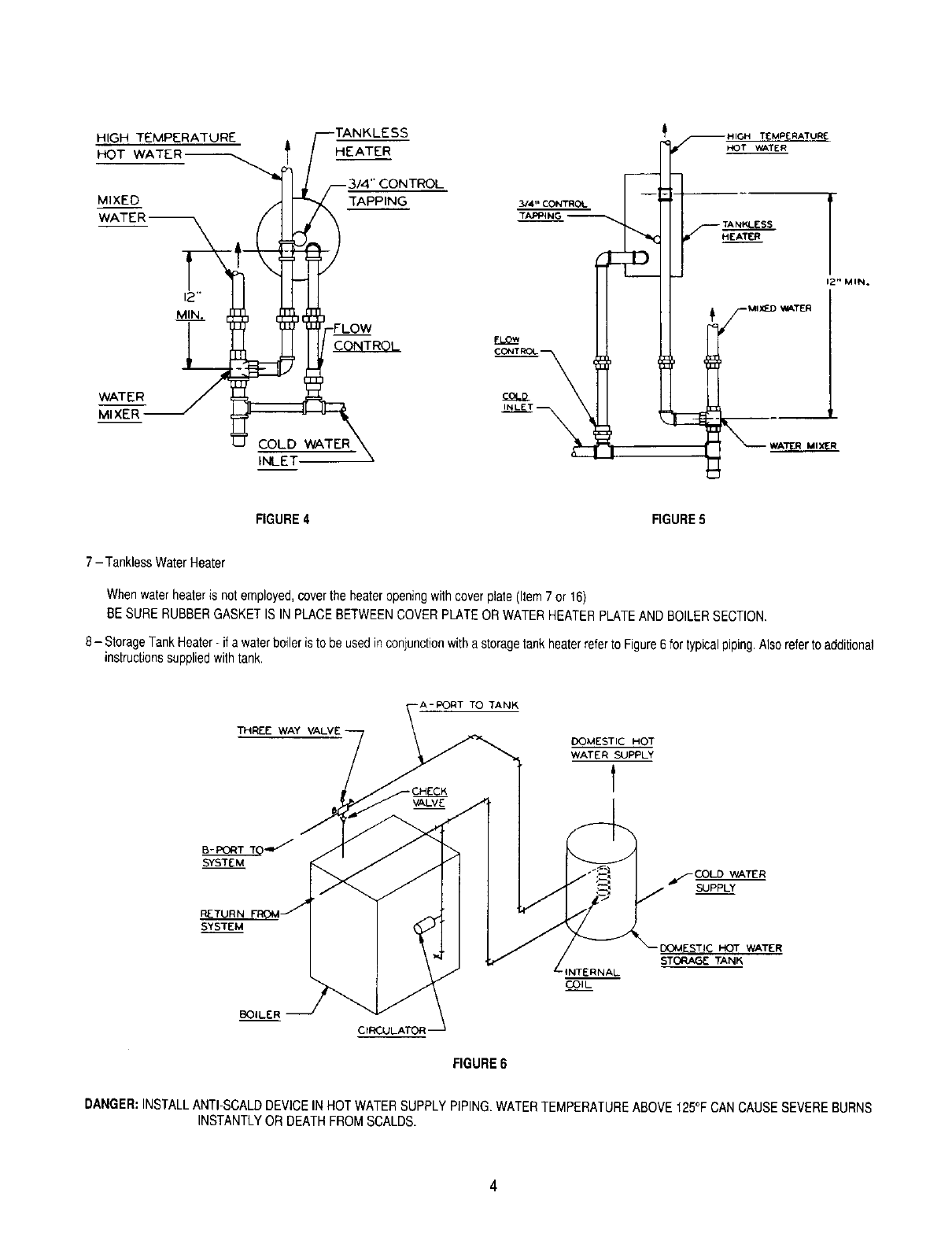
FIGURE4 FIGURE5
7 -Tankless WaterHeater
Whenwaterheateris not employed,coverthe heateropeningwith coverplate(Item7 or 16)
BESURERUBBERGASKETIS IN PLACEBETWEENCOVERPLATEORWATERHEATERPLATEAND BOILERSECTION.
8- StorageTank Heater- if a waterboileris to be usedin conjunctionwitha storagetank heaterreferto Figure6 fortypicalpiping.Alsoreferto additional
instructionssuppliedwith tank,
THREE WAY VALVE
DOMESTIC HOT
WATER SUPPLY
SYSTEM
RETURN
SYSTEM
BOILER
FIGURE6
INTERNAL
CO_L_
fCOLDWATER
SUPPLY
DOMESTIC HOT WATER
ST0f_AC-.,_:TANK
DANGER:INSTALLANTI-SCALDDEVICEINHOT WATERSUPPLYPIPING.WATERTEMPERATUREABOVE125°FCANCAUSESEVEREBURNS
INSTANTLYOR DEATHFROMSCALDS.
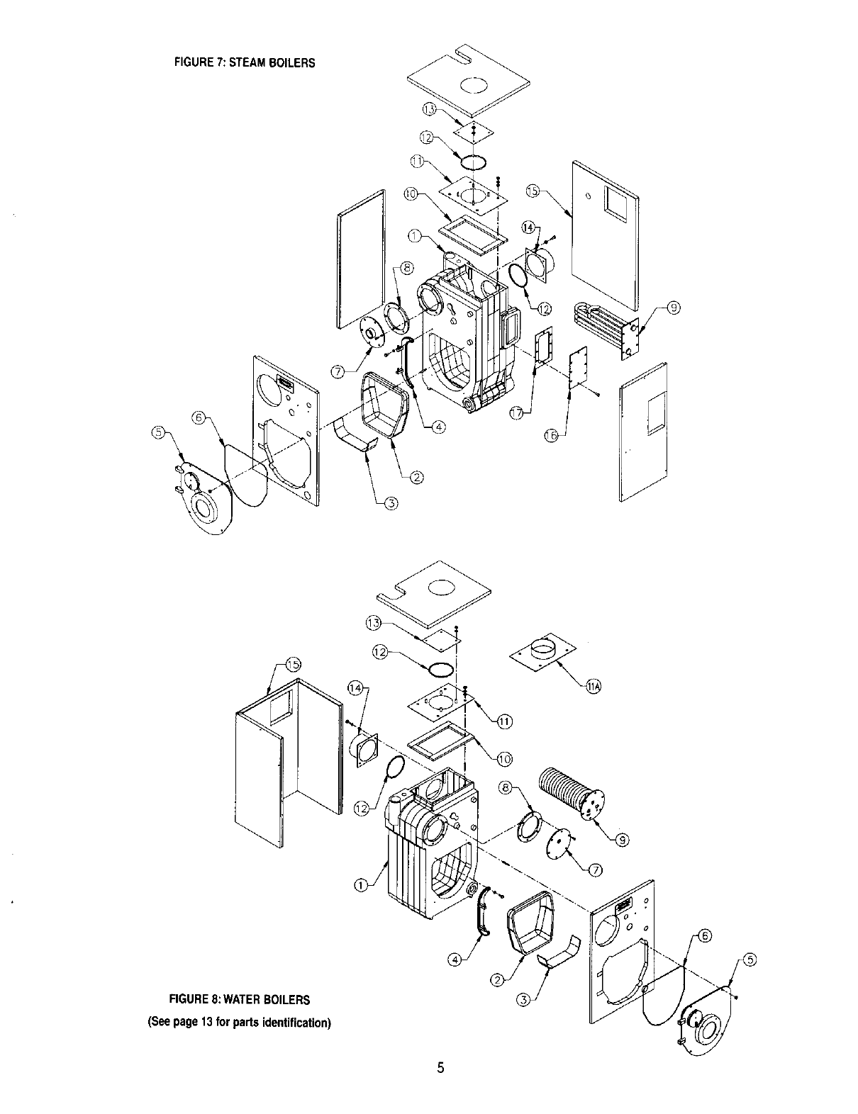
FIGURE7:STEAMBOILERS
FIGURE8:WATERBOILERS
(See page 13for parts identification)
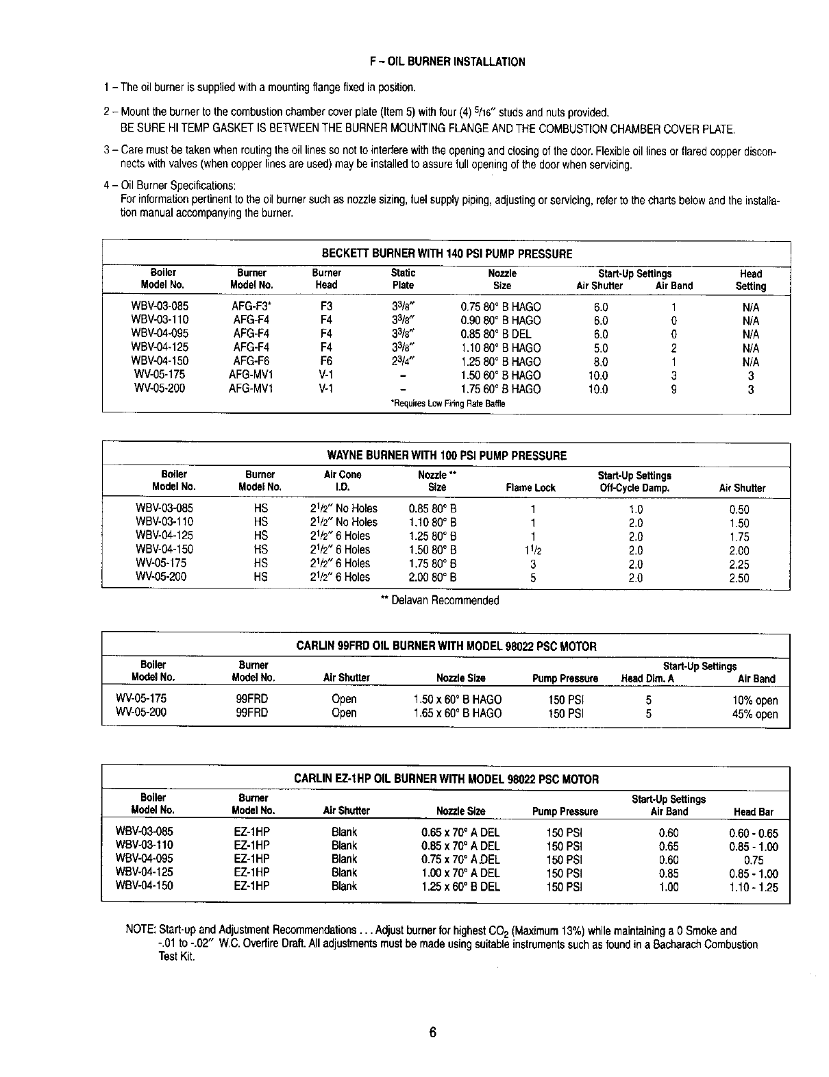
F- OILBURNERINSTALLATION
1-The oil burneris suppliedwitha mountingflangefixed in position.
2 - Mounttheburner to the combustionchambercoverplate(Item5) withfour (4) 5/r6"studsand nutsprovided.
BE SUREHI TEMPGASKETIS BETWEENTHE BURNERMOUNTINGFLANGEANDTHECOMBUSTIONCHAMBERCOVERPLATE.
3-Caremustbe takenwhen routingthe oil lines so not to interferewith theopeningand closingof the door.Flexibleoil linesor flaredcopperdiscon-
nectswithvalves(whencopperlinesare used) maybe installedto assurefull openingof the door whenservicing.
4-Oil BurnerSpecifications:
Forinformationpertinentto the oil burnersuch as nozzlesizing,fuel supplypiping,adjustingor servicing,referto the chartsbelowand theinstalla-
tion manualaccompanyingthe burner.
BECKETTBURNERWITH140 PSIPUMPPRESSURE
Boiler Burner Burner Static Nozzle Start-UpSettings Head
ModelNo, ModelNo. Head Plate Size AirShutter AirBand Setting
WBV-03-085 AFG-F3* F3 33/8" 0.7580" B HAGO 6.0 1 N/A
WBV-03-110 AFG-F4 F4 33/8" 0.9080° B HAGO 6.0 0 N/A
WBV-04-095 AFG-F4 F4 33/8" 0.85800B DEL 6.0 0 N/A
WBV-04-125 AFG-F4 F4 33/8" 1.10800B HAGO 5.0 2 N/A
WBV-04-150 AFG-F6 F6 23/4" 1.25800B HAGO 8.0 1 N/A
WV-05-175 AFG-MV1 V-1 1.5060° B HAGO 10.0 3 3
WV-05-200 AFG-MV1 V-1 1.7560° B HAGO 10.0 9 3
*RequiresLow F_ringRateBaffle
WAYNEBURNERWITH 100PSIPUMPPRESSURE
Boiler Burner AirCone Nozzle** Start-UpSettings
ModelNo, ModelNo, I,D. Size FlameLock Off-CycleDamp, AirShutter
WBV-03-085 HS 21/2" NoHoles 0.85 80° B 1 t.0 0.50
WBV-03-110 HS 21/2"NoHoles 1.10 80" B 1 2.0 1.50
WBV-04-125 HS 21/2"6 Holes 1.25 80° B 1 2.0 1.75
WBV-04-150 HS 21/2,, 6 Holes 1.50 80°B 1!/2 2.0 2.00
WV-05-175 HS 21/2"6 Holes 1.75 80° 8 3 2.0 2,25
WV-05-200 HS 21/2"6 Holes 2.00 80° B 5 2.0 2.50
** DelavanRecommended
CARLIN99FRDOIL BURNERWITHMODEL98022PSCMOTOR
Boiler Burner Start-UpSettings
ModelNo. ModelNo. AirShutter NozzleSize PumpPressure HeadDim.A AirBand
WV-05-175 99FRD Open 1.50x 600B HAGO 150PSi 5 10%open
WV-05-200 99FRD Open 1.65x 600B HAGO 150PSI 5 45%open
CARLINEZ-1HPOIL BURNERWITHMODEL98022PSCMOTOR
Boiler Burner Start-UpSettings
ModelNo. ModelNo. AirShutter NozzleSize PumpPressure AirBand HeadBar
WBV-03-085 EZ-IHP Blank 0.65 x 70° ADEL 150PSI 0.60 0.60- 0.65
WBV-03-f10 EZ-1HP Blank 0.85 x 700ADEL 150 PSI 0.65 0.85- 1.00
WBV-04-095 EZ-1HP Blank 0.75 x 70°A.DEL 150 PSI 0.60 0.75
WBV-04-125 EZ-1HP Blank 1.00x 700A DEL 150PSI 0.85 0.85- 1.00
WBV-04-150 EZ-1HP Blank 1.25x 60° B DEL 150 PSI 1.00 1.10- 1.25
NOTE:Start-upandAdjustmentRecommendations...AdjustburnerforhighestCO2(Maximum13%)whilemaintaininga 0 Smokeand
-.01 to -.02" W.C.OverfireDraft.All adjustmentsmustbe madeusing suitableinstrumentssuch asfound in a 8acharachCombustion
TestKit.
6
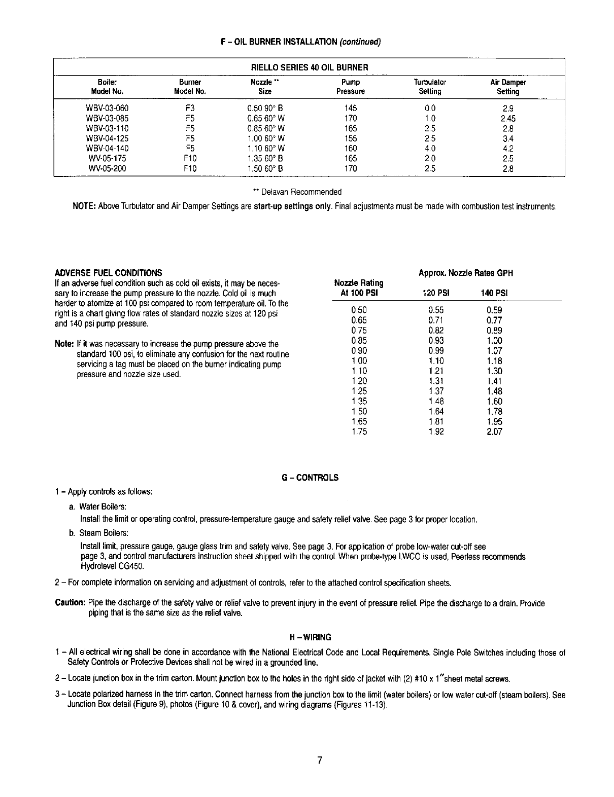
F - OIL BURNERINSTALLATION(continued)
RIELLOSERIES40 OIL BURNER
Boiler Burner Nozzle** Pump Turbulator AirDamper
ModelNo. ModelNO. Size Pressure Setting Setting
WBV-03-060 F3 0.50 90° B 145 0.0 2.9
WBV-03-085 F5 0.65 60" W 170 1.0 2.45
WBV-03-110 F5 0.85 60° W 165 2.5 2.8
WBV-04-125 F5 1.0060° W 155 25 3.4
WBV-04-140 F5 1.1060°W 160 4.0 4.2
WV-05-175 F10 1.3560" B 165 2.0 2.5
WV-05-200 F10 1.5060° B 170 2.5 2.8
** DelavanRecommended
NOTE:AboveTurbulatorandAir DamperSetlingsare start-upsettings only. Finaladjustmentsmustbe madewithcombustiontestinstruments.
ADVERSEFUELCONDITIONS
Ifanadversefuelconditionsuchas coldoilexists,itmaybeneces-
sarytoincreasethepumppressuretothenozzle.Coldoilis much
harderto atomizeat 100psicomparedto roomtemperatureoil.Tothe
rightis a chart giving flowrates of standardnozzlesizesat 120 psi
and 140psi pumppressure.
Note:If itwasnecessaryto increasethe pumppressureabovethe
standard100psi,toeliminateanyconfusionfor thenextroutine
servicinga tagmustbe placedontheburnerindicatingpump
pressureandnozzlesizeused.
Approx.NozzleRatesGPH
NozzleRating
At 100 PSI 120PSI 140 PSI
0.50 0.55 0.59
0.65 0.71 0.77
0.75 0.82 0.89
0.85 0.93 1.00
0.90 0.99 1.07
1.00 1.10 1.18
1.10 1.21 1.30
1.20 1.31 1.41
1.25 1.37 1.48
1.35 1.48 1.60
1.50 1.64 1.78
1.65 1.81 1.95
1.75 1.92 2.07
G-CONTROLS
1 - Applycontrolsas follows:
a. WaterBoilers:
Installthelimitoroperatingcontrol,pressure-temperaturegaugeandsafetyreliefvalve.Seepage3 for properlocation.
b. SteamBoilers:
Installlimit,pressuregauge,gaugeglasstrim andsafetyvalve.Seepage3. Forapplicationof probelow-watercut-offsee
page3, andcontrolmanufacturersinstructionsheetshippedwiththecontrol.Whenprobe-typeLWCOis used,Peerlessrecommends
HydrofavelCG450.
2- Forcompleteinformationonservicingandadjustmentofcontrols,refertotheattachedcontrolspecificationsheets.
Caution:Pipethe dischargeofthe safetyvalveorreliefvalveto preventinjuryinthe eventofpressurerelief.Pipethedischargeto a drain.Provide
pipingthatis thesamesizeasthereliefvalve.
H-WIRING
1-All electricalwiringshallbe doneinaccordancewiththeNationalElectricalCodeand LocalRequirements.Single PoleSwitchesincludingthoseof
Safety Controlsor ProtectiveDevicesshall notbewired ina groundedline.
2 - Locatejunctionboxin thetrim carton.Mountjunctionboxto theholesin the rightside of jacketwith (2)#10 x 1"sheetmetalscrews.
3 - Locatepolarizedharnessin thetrim carton.Connectharnessfromthe junctionbox to the limit (waterboilers)or lowwatercut-off(steamboilers).See
JunctionBox detail(Figure9), photos(Figure10 & cover),and wiringdiagrams(Figures11-13).
7
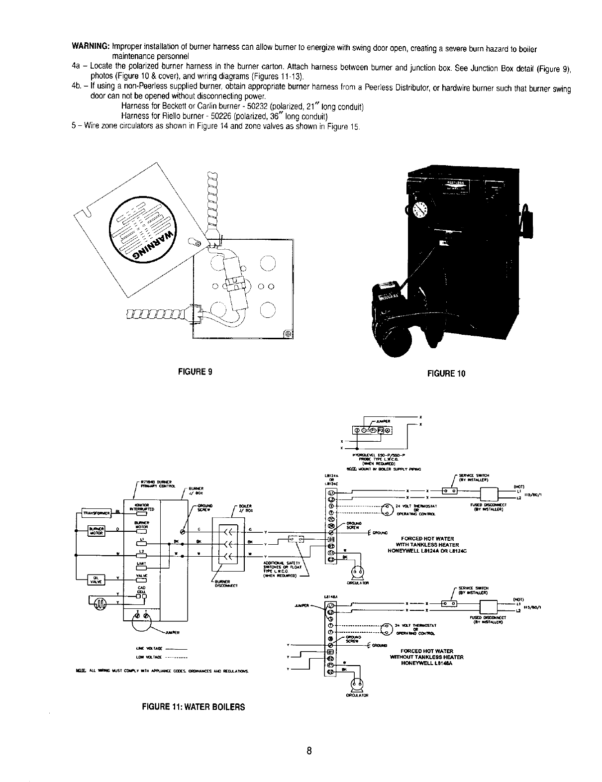
WARNING:Improperinstallationof burnerharnesscanallowburnerto energizewithswingdooropen,creatingasevereburnhazardto boiler
maintenancepersonnel
4a - Locatethe polarizedburnerharness in theburnercarton. Attachharness betweenburner andjunction box. SeeJunctionBox detail (Figure9),
photos(Figure 10& cover),and wiringdiagrams(Figures11-13).
4b.- If using a non-Peerlesssuppliedburner,obtain appropriateburnerharnessfroma PeerlessDistributor,or hardwireburnersuch that burnerswing
doorcannot beopenedwithoutdisconnectingpower.
Harnessfor Beckettor Cadinburner- 50232(polarized,21" longconduit)
Harnessfor Rielloburner- 50226(polarized,36" long conduit)
5 Wirezone circulatorsas shownin Figure14and zonevalvesas shownin Figure15
©©
FIGURE9 FIGURE10
p_,:,dr_ CONT_O. OI_,_R • {WJT)
J/oo_ _ • ii s/qso/I
iws_ FORCED HOT WATER
-- WtTH TANKLES_ HEATER
, - _HONEYWELL L8124A OR L8124C
t'l_ *I, CO
WW_OUT TANKLESS HEATER
• _ HONEYWELL L8148A
cr_c_U_TO_
FIGURE11:WATERBOILERS
w
Y
_GNITOR l
BURNER
LIMIT
CAD
F,, ,
OPERATING CONTROL
FOR STEAU W/
TANKLESS HEATI_R ONLy
BC4LER TGROUND
J/ BOX
_OUNO
SCREW _ J/_GROUNB
G O SCREW ADDITIONAL
<_ UMIT SAFETY S_ TCHES
i-1-,_=
LBURNER _SER_C[ S_TCH
BI_NEBT _(BY INSTAL_.[R)
STEAM WITH OR _(HOT)
WITHOUTHEATERTANKLESS I _L2L•_$5/60/I
FUSED DISCONNECT
(BY INSTALLER)
24v _HERMOSTAT
--LINE VOLTAGE
........... LOW VOLTACE
ALL VelRING MUST COMPLY "t_TH ApI_LIANCE COO_S, (_O_NANCE5 AND REGULATIONS
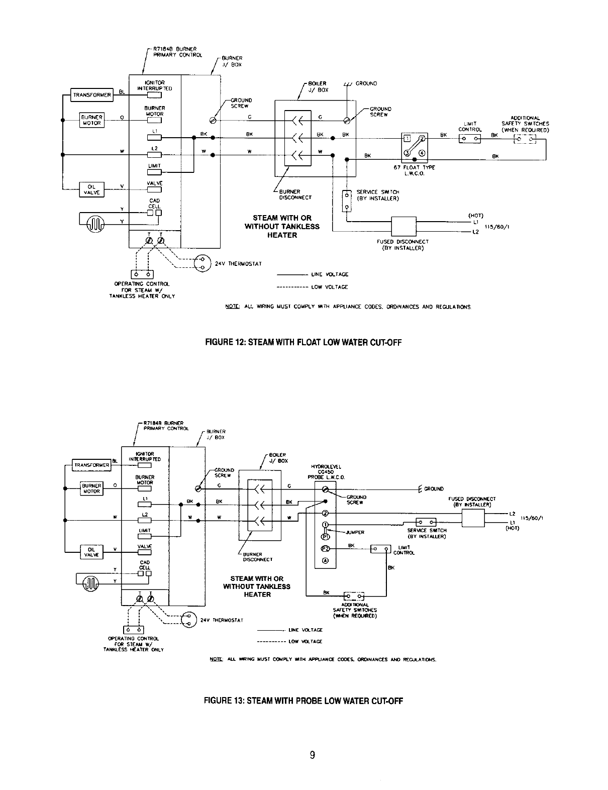
FIGURE12:STEAMWITHFLOATLOWWATERCUT-OFF
w
,{
OP_RATIN GCaN TROL
TANI_ESS _a_R I_ILy
R71_B OIJI_ER /
PRIMARY CONmOL BURNER
J/ BOX
IGNITOR 8_LER
_rED J/ BOX H YDROtE',_ L
ROUND CG4_ O
BURNER SCREW pROB ELWC0
LI 8K K GROUND FUS/ED D4SCONNECT
LIM_T JUMPER _R_ lee S_TCH (HOT/
_URN_ R CONTROL[] STEAM WITH OR
WITHOUT TANKLESS
t" / ", , SAFETY S_ITCPE5
: _ "_ ..... -_) 24v THERMOSTAT
__ LIN_ VOLTAG_
.......... LOW VOL T&GE
ALL _q_ING MUST [_OMPLY I_TH APPLIANC_ C(_S, (_NAN{_S ANO R_GU_AIIONS
FIGURE13: STEAMWITH PROBELOWWATERCUT-OFF

LINE VOLTAGE
LOW VOLTAGE
CIRCULATOR
NOTE:
ALL WIPING MU_T COMPLY WITH APPLICABLE
CODES,ORDINANCES_AND REGULATIONS. ZONE #l ZONE _B ZONE _3
-.+ _
FIGURE14: ZONINGWITHCIRCULATORS
iBOV - 6OMZ
TO MAIN
DISCONNECT
12o/z4v SOHZ _
4OVA _LIL2 I I
I
BOX
©
II
i I
j I
I
I
I
I
I
I
J
ALL WIRING MUST COMPLY WITH APPLICAI__E
CODES IORDINANCES t AND REGULATIONS .
FIGURE15: ZONINGWITHZONEVALVES
10
L2 LI
TO PEERLESS
PARTNER C:RCULAiOR
_O ZONE ]
SPACE HE ATIN_
THERMOSTAT
TO MAIN ,r_-A _"
DISCONNECT
---(9
®
i LINE VOLTAGE
...... LOW VOLTAGE
BOILER LIMIT
HONEYWELL LB148A
TO BOILER TO BURNER
CIRCULATOR DISCONNECT
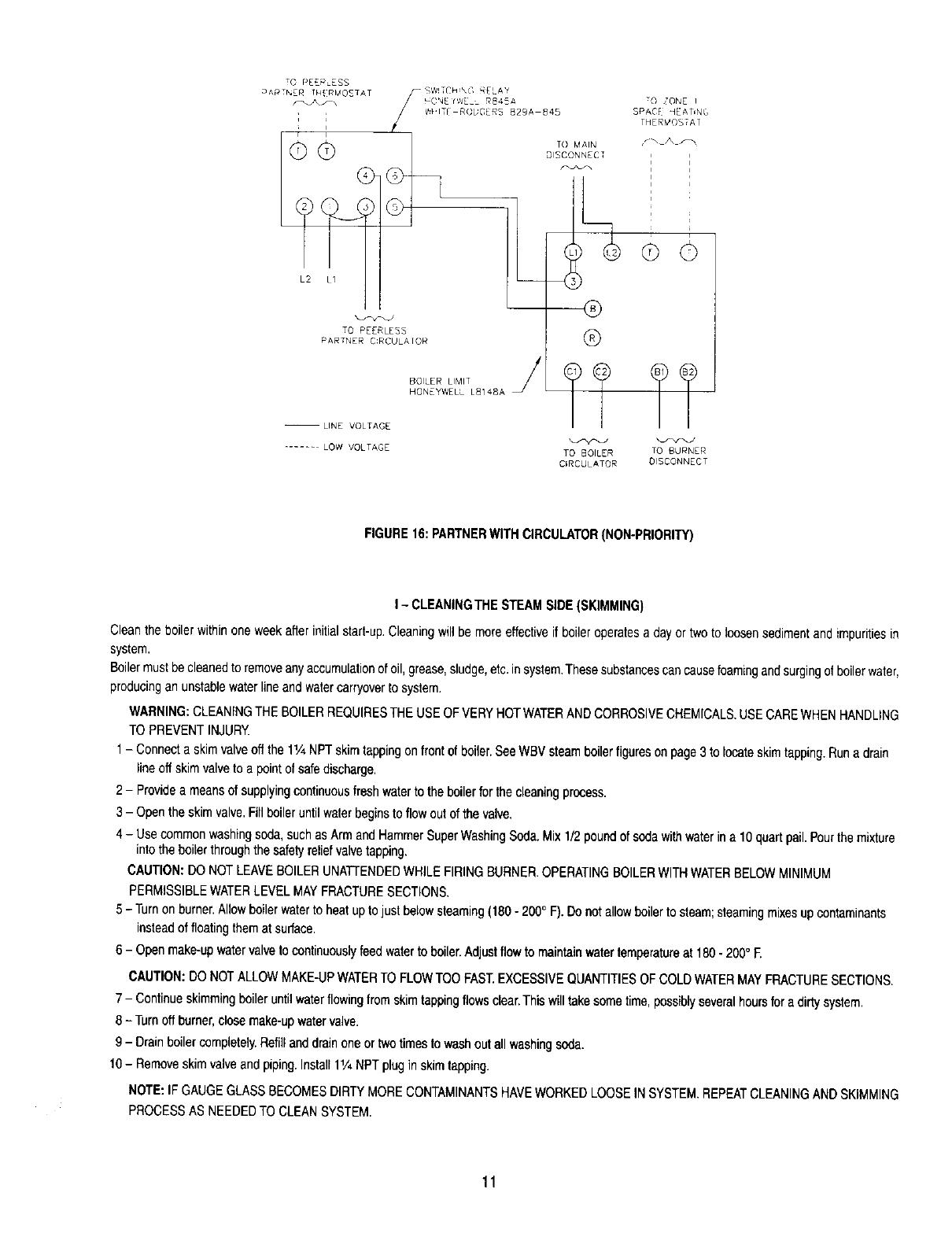
FIGURE16:PARTNERWITHCIRCULATOR(NON-PRIORITY)
I-CLEANINGTHESTEAMSIDE(SKIMMING)
Cleanthe boiler withinone week afterinitialstart-up.Cleaningwill be moreeffectiveif boileroperatesa day or twoto loosensedimentand impuritiesin
system.
Boilermustbe cleanedto removeanyaccumulationof oil,grease,sludge,etc. insystem,Thesesubstancescan causefoamingandsurgingof boilerwater,
producingan unstablewaterline and watercarryoverto system.
WARNING:CLEANINGTHEBOILERREQUIRESTHEUSEOFVERYHOTWATERAND CORROSIVECHEMICALS.USECAREWHENHANDLING
TOPREVENTINJURY.
1- Connecta skimvalveoff the11/,NPTskimtappingonfrontof boiler.SeeWBVsteam boilerfigureson page3 to locateskim tapping.Runa drain
lineoff skimvalveto a pointof safedischarge.
2 - Providea meansof supplyingcontinuousfresh waterto the boilerfor thecleaningprocess.
3 - Openthe skim valve.Fillboileruntil waterbeginsto flow outof the valve.
4 - Usecommonwashingsoda,suchasArmandHammerSuperWashingSoda.Mix 1/2 poundof sodawithwaterin a 10quart pail.Pourthemixture
intothe boilerthroughthe safetyreliefvalvetapping.
CAUTION:DONOT LEAVEBOILERUNATTENDEDWHILEFIRINGBURNER.OPERATINGBOILERWITHWATERBELOWMINIMUM
PERMISSIBLEWATERLEVELMAYFRACTURESECTIONS.
5 - Turnon burner.Allowboilerwaterto heatup tojust belowsteaming(180- 200° F).Donot allowboilerto steam;steamingmixesupcontaminants
insteadof floatingthem at surface.
6 - Openmake-upwatervalvetocontinuouslyfeed waterto boiler.Adjustflowto maintainwatertemperatureat 180- 200°E
CAUTION:DONOTALLOWMAKE-UPWATERTO FLOWTOOFAST.EXCESSIVEQUANTITIESOFCOLDWATERMAYFRACTURESECTIONS.
7 - Continueskimmingboiler untilwaterflowingfromskimtappingflowsclear.This willtakesome time,possiblyseveralhoursfora dirty system.
8 - Turnoff burner,close make-upwatervalve.
9 - Drain boilercompletely.Refilland drainone or twotimesto wash out all washingsoda.
10- Removeskim valveand piping.Install11/4NPTplugin skimtapping.
NOTE:IF GAUGEGLASSBECOMESDIRTYMORECONTAMINANTSHAVEWORKEDLOOSEIN SYSTEM.REPEATCLEANINGANDSKIMMING
PROCESSAS NEEDEDTO CLEANSYSTEM.
11
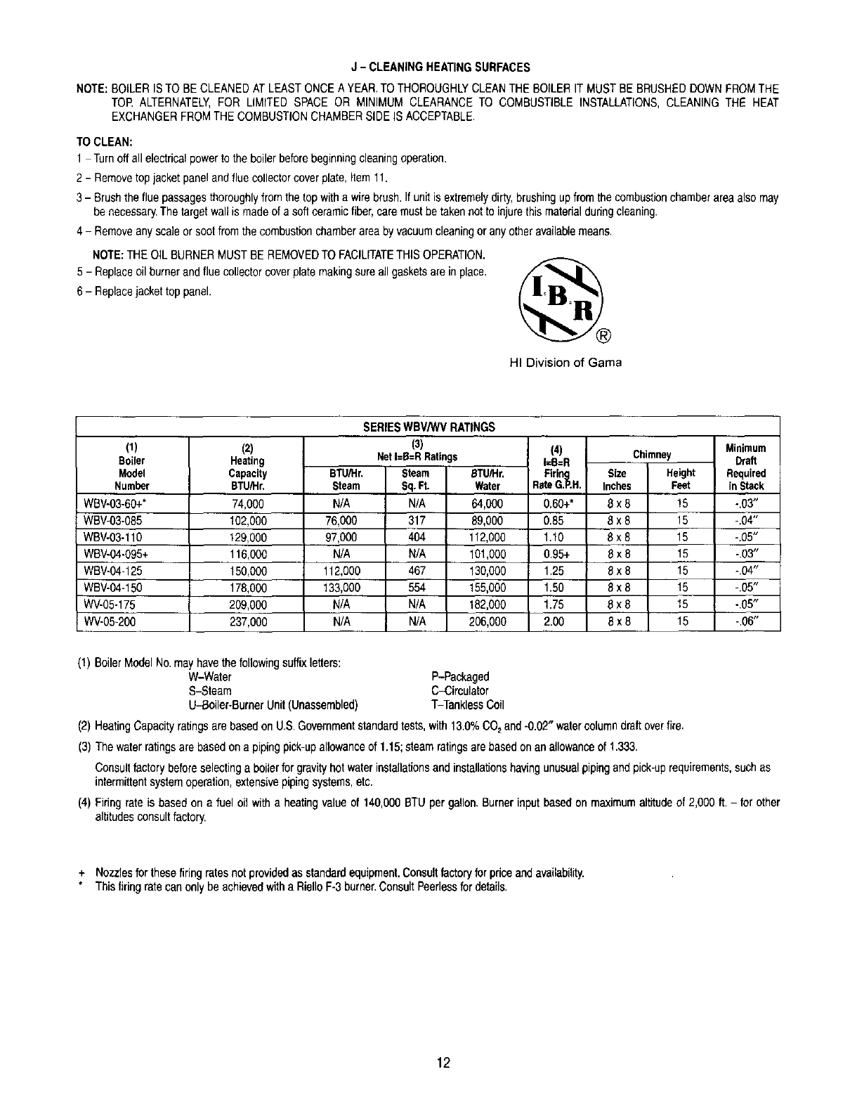
J-CLEANINGHEATINGSURFACES
NOTE:BOILERISTO BE CLEANEDATLEASTONCEA YEAR.TOTHOROUGHLYCLEANTHE BOILERITMUST BE BRUSHEDDOWNFROMTHE
TOE ALTERNATELY,FOR LIMITEDSPACE OR MINIMUMCLEARANCETO COMBUSTIBLEINSTALLATIONS,CLEANINGTHE HEAT
EXCHANGERFROMTHE COMBUSTIONCHAMBERSIDE IS ACCEPTABLE.
TOCLEAN:
1 Turnoffall electricalpowerto the boiler beforebeginningcleaningoperation.
2 - Removetopjacketpaneland fluecollectorcoverplate,item 11.
3 - Brushthe fluepassagesthoroughlyfromthetop witha wire brush.If unitis extremelydirty,brushingup fromthe combustionchamberareaalso may
be necessaryThe target wall is madeof a soft ceramicfiber,care mustbe takennotto injurethis materialduringcleaning.
4 - Removeany scale or sootfromthe combustionchamberareaby vacuumcleaningor anyotheravailablemeans.
NOTE:THEOIL BURNERMUSTBE REMOVEDTO FACILITATETHISOPERATION.
5 - Replaceoil burnerandflue collectorcoverplatemakingsureall gasketsare in place.
6 - Replacejacket toppanel.
HI Division of Gama
(1)
Boiler
Model
Number
WBV-03-60+*
WBV-03-085
WBV-03-110
WBV-04-095+
WBV-04-125
WBV-04-150
WV-05-175
! WV-05-200
(2)
Heating
Capacity
BTU/I-In
74,000
!02,000
129,000
116,000
150,000
178,000
209,000
237,000
SERIESWBV/WVRATINGS
(3)
NetI=B=RRatings
BTU/Hr, Steam BTU/Hr.
Steam Sq.R. Water
N/A N/A 64,000
76,000 317 89,000
97,000 404 112,000
N/A N/A 101,000
112,000 467 130,000
133,000 554 155,000
N/A N/A 182,000
N/A N/A 206,000
(4)
1=8=R
Firing
RateG.P.H.
0.60+*
0.85
1.10
0.95+
1.25
1.50
1.75
2.00
Chimney
Size Height
Inches Feet
6x8 !5
8x8 15
8x8 15
6x8 15
8x8 15
8x8 15
8x8 15
8x8 15
Minimum
Draft
Required
inStack
-.03"
-.04"
-.05"
-.03"
-,04"
-,05"
-,05"
-.06"
(1) BoilerModelNo.mayhavethefollowingsuffixletters:
W-Water P-Packaged
S-Steam C-Circulator
Uq_oiler-BurnerUnit(Unassembled) T-TanklessCoil
(2) HeatingCapacityratingsarebasedonU.S.Governmentstandardtests,with13.0%CO2and-0.02" watercolumndraftoverfire.
(3) Thewaterratingsare based ona pipingpick-upallowanceof 1.15;steam ratingsarebasedonanallowanceof 1.333.
Consultfactorybeforeselectingaboilerfor gravityhotwaterinstallationsandinstallationshavingunusualpipingandpick-uprequirements,such as
intermittentsystemoperation,extensivepipingsystems,etc.
(4) Firingrateis based on a fueloilwith a heatingvalueof 140,000BTU pergallon.Burnerinputbasedonmaximumaltitudeof 2,000ft. -for other
altitudesconsultfactory.
+ Nozzlesfor thesefiring ratesnot providedas standardequipment.Consultfactoryforprice andavailability.
* Thisfiringrate canonly be achievedwitha Riello F-3burner.ConsultPeerlessfor details.
12
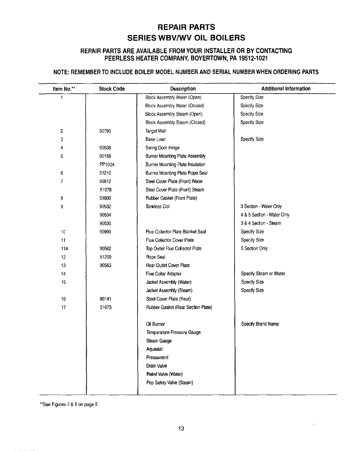
REPAIR PARTS
SERIES WBV/WV OIL BOILERS
REPAIR PARTSARE AVAILABLEFROMYOUR INSTALLER OR BY CONTACTING
PEERLESS HEATERCOMPANY,BOYERTOWN,PA 19512-1021
NOTE: REMEMBER TO INCLUDE BOILER MODEL NUMBER AND SERIAL NUMBER WHEN ORDERING PARTS
ItemNo.** StockCode
1
2
3
4
5
10
11
11A
12
13
14
15
16
17
50795
90538
90158
PP1004
51210
99812
X1078
51800
90532
90534
90530
90999
90562
51209
90563
90141
51673
Description
Block AssemblyWater(Open)
BlockAssemblyWater(Closed)
BlockAssemblySteam(Open)
BlockAssemblySteam(Closed)
TargetWall
BaseLiner
SwingDoorHinge
BurnerMountingPlateAssembly
BurnerMountingPlateInsulation
BurnerMountingPlateRopeSeal
SteelCoverPlate(Front)Water
SteelCoverPlate(Front)Steam
RubberGasket(FrontPlate)
TanklessCoil
RueCollectorPlateBlanketSeal
FlueCollectorCoverPlate
TopOutletFlueCollectorPlate
RopeSeal
RearOutletCoverPlate
FlueCollarAdapter
JacketAssembly(Water)
JacketAssembly(Steam)
SteelCoverPlate(Rear)
RubberGasket(RearSectionPlate)
OilBurner
Temperature-PressureGauge
SteamGauge
Aquaatat
Pressuretrol
DrainValve
ReliefValve(Water)
PopSafetyValve(Steam)
Additional Information
SpecifySize
SpecifySize
SpecifySize
SpecifySize
SpecifySize
3 Section-WaterOnly
4 & 5 Section-WaterOnly
3 & 4 Section-Steam
SpecifySize
SpecifySize
5 SectionOnly
SpecifySteamor Water
SpecifySize
SpecifySize
SpecifyBrandName
**SeeFigures7 & 8 on page5
13
Series WBV/WV
OH Boilers
Installation,
Operation b
Maintenance
Manual
TO THE INSTALLER:
This manual is the property of the owner and must
be affixed near the boiler for future reference.
TO THE OWNER:
This boiler should be inspected annually by a
Qualified Service Agency.
HI Division ASME
of gama
pr=-r=-RLESS *
CAST IRON BOILERS
PEERLESS HEATER COMPANY
231 NORTH WALNUT STREET • BOYERTOWN, PA 19512-1021 • PHONE 610-367-2153
www.peerless-heater, com
THE PREFERRED HEATING CHOICE
©2002 Peerless Heater Company PP8046 R14 (10/02-10M)
Printed in U.S,A.
