PEERLESS Boiler Manual L0308198
User Manual: PEERLESS PEERLESS Boiler Manual PEERLESS Boiler Owner's Manual, PEERLESS Boiler installation guides
Open the PDF directly: View PDF ![]() .
.
Page Count: 24
SC/SCT
Gas/Off Boilers
Installation,
Operation b
Maintenance
Manual
PEERLESS _
CAST IRON BOILERS

6 Sizes
" Oil, Gas or Comb|nhtion G_s
Knockdown (Factory Assembled Split Block Sections)
or Packaged Hot Water or Steam Boilers
5-10 Sections 3.0 to 5.5 GPH Input Up to 83.7% Combustion Efficiency
Forced Draft Venting
•Only Requires a Three Foot Vent Above the Roof
High Efficiency Power Burners
•Choice ofBeckett, Carlin, Gordon-Piatt, Power Flame or Webster
Top Flue Outlet
•Includes Locking Damper
Large Water Content, Wet Base Section Design
•Ideal for Steam and Large Volume Hot Water Jobs
Steel Push Nipples
• Provide aPermca_cmt Water Tight S_al Belween Sections
•Unaj]'_cted by Petroleum and Other Conlaminanis
Easy to Clean
•Flueways ca_ be Cleanedj-rom Either ih__I_Ji Side or Top
Safety Controls
• Probe or Float Type Low Water Cut-OffAvailable
Tankless Coils
•For Domestic Hot Water Production on Hot Water Boilers
Deluxe Insulated Enameled Steel Jacket
•Reduces Boiler Heat Loss
•Honeywell Operating Controls
•Manual Reset High Limit Control
•LWCO on Packaged Boilers
•Tankless Coils
•Various Burner Options and Voltages
•FM and IRI Control Systems
Peerless Heal_,r Company is pleased Io offer o_lL" of lhe illosf compreh_nsiw! warranty programs
in the inda,slry. All Peerless conmlercial cast iron boilers include a fi_ll, one y_'ar warranty. A [_I_-_-_r'SS®
limited, fen year warr(mty ol_ the ca.sl troll sections is provided Jbr all commercial lint water and
steam boilers. Five cmd len-year t_xIt!llded wanantics on paris and labor are flow auailable. CAST IRON BOILERS
Ple_e Colisttll I)(,('rless [ ]_'_llt,r ColllpCllly.lbr COTil[)lt_l_! warrallly iqtbrnlalioll.
Peerless Heater Company •231 North Walnut Street •Boyertown, PA 19512-i021 •610-367 2153 •wv_v.peerless-heater.com
FAB SC R3 (11/02 1 5M)
Pnnted in U S A
pr=-r=-RLESS
CAST IRON BOILERS
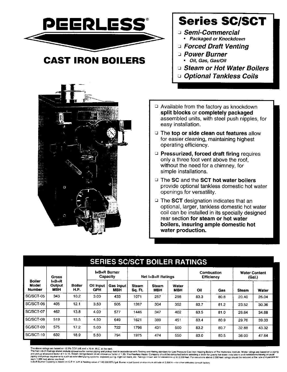
Series SC/SCT
Semi-Commercial
•Packaged or Knockdown
Forced Draft Venting
Power Burner
•Oil, Gas, Gas/Oil
JSteam or Hot Water Boilers
Optional Tankless Coils
Available from the factory as knockdown
split blocks or completely packaged
assembled units, with steel push nipples, for
easy installation.
The top or side clean out features allow
for easier cleaning, maintaining highest
operating efficiency.
Pressurized, forced draft firing requires
only a three foot vent above the roof,
without the need for a chimney, for
simple installations.
The SC and the SOT hot water boilers
provide optional tankless domestic hot water
openings for versatility.
The SCT designation indicates that an
optional, larger, tankless domestic hot water
coil can be installed in its specially designed
rear section for steam or hot water
boilers, insuring ample domestic hot
water production.
I=B=R Burner Combustion Water Content
Capacity Net I=B=R Ratings Efficiency (Gal.)
Uoiler I=B=H
Model Output Boiler Oil Input Gas Input Steam Steam Water
Number MBH H.P. GPH MBH Sq. Ft. MBH MBH Oil Gas Steam Water
SC/SCT-05 343 10.2 3.00 433 1071 257 298 83.3 80.8 20.40 26.04
SC/SCT-06 405 12.1 3,50 505 1267 304 352 83.7 81.2 23.52 30.36
SC/SCT-07 462 13.8 4.00 577 1446 347 402 83.5 81.0 26.64 34.68
SC/SCT-O8 519 15.5 4.50 649 1621 389 451 83.4 80.9 29.76 39.03
SC/SCT-09 575 17.2 5.00 722 1796 431 500 83.2 80.7 32.88 43.32
SC/SCT-10 632 18.9 5.50 794 474 550 83.0 80.5 36.00
The above catings are based on 12 5% CO2 (oil) and +10 in W.C at Ihe vent
TPe Net I-B=R Ra_ngs shown include a_k:wance fo_ notma_ p_ping and p_c_up load in accordance w_h T_st_g and Ral_g st_e_lafdfor LOW pressure Cast IrOn Heatbng Boilers of The V_/dren_s Institute Water rahngs are base_l on ap_F.ng
and p_kup a_lowan_ factor of 1to 15 Steam ral_ngs based on aM ar_owaece factor of I 33 The Peedess Heater Company should b_ consu,ed before selectbng a boiler for grarity hot wale_ installations and _ns_a_ations havir_ unusual
F.plng and p_kup requkements such as extended p_p_ng systems¸ exposed piping¸ night set back. et¢ Rallngs shown a_e for e_evaticns up IO 2C00 lear For e_evations above 2.OO0 feet ratings sheul_ be _educed at the rate of 4petce_t for
each 1C_O leer above sea level
I B R Burner Capacity is based on G P H with a heat,rig va_ue of 14OOOO @TU/gal Burner ,nput base_ on maximum altitude of 2¸O0O _ _or o_e_ aWtud_ ¢onsu_ _actory
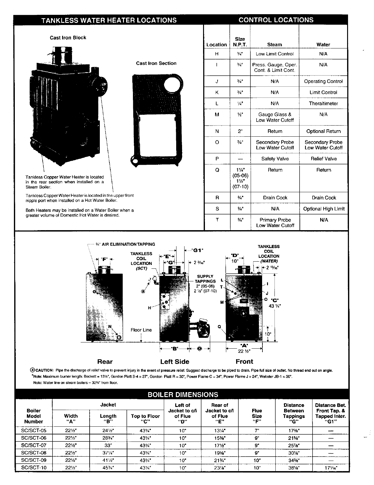
Cast Iron Block
Steam Boitar.
Tankless Copper Water Heater is located in the upper front
nipple port when installed on a Hot Water Boiler.
Both Heaters may be installed on a Water Boiter when a
greater volume of Domestic Hot Water is desired.
Cast Iron Section
E
H
I
J
K
L
M _/2"
p
Q 11/4"
(05-06)
l_/z"
(07-10)
Steam Water
3/4" Low Limit Control N/A
3/4" Press• Gauge, Oper. N/A
Cont. & Limit Cont.
3/4" N/A Operating Control
3/4" N/A Limit Control
1/4" N/A Theraltimeter
Gauge Glass & N/A
Low Water Cutoff
Return Optional Return
Secondary Probe Secondary Probe
Low Water Cutoff Low Water Cutoff
Safety Valve Relief Valve
Return Return
R 3/4" Drain Cock Drain Cock
s
T
3/4" N/A Optional High Limit
3/4" Primary Probe N/A
Low Water Cutoff
Boiler
Model
Number
SC/SCT-O5
SC/SCT-06
SC/SCT-07
SC/SCT-08
SC/SCT-09
SC/SCT-IO
Width
"A"
22_/2"
22_/z"
22V2"
22_/2"
22V2"
22V2"
Length
"B"
24_/2"
28_'4"
33"
371/4"
41V2"
453/,"
Top to Floor
-C-
431/4"
43V4"
43V4"
43%"
43V4"
43%"
of Flue
"D"
10"
10"
10"
10"
10"
10"
of Flue
"E"
131/4"
15%"
171_"
19%"
21¾"
23%"
Size
-F-
7"
9"
9"
9"
10"
10"
Tappings
-G-
17%"
21-%"
257/_"
301/e"
34_'B"
38%"
Tapped Inter.
"G1"
17_/_6"
I ",11".JI_(e]lV]f_e]_F_l
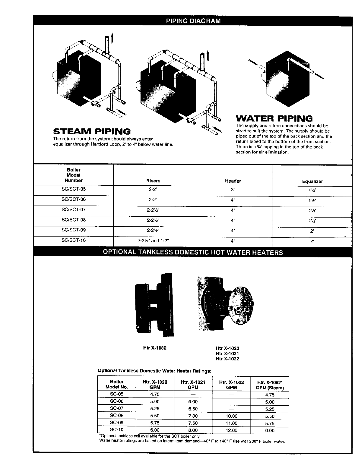
STEAM PIPING
The return from the system should always enter
equalizer through Har[ford Loop, 2" to 4" below water line.
%.
WATER PIPING
The supply and return connections should be
sized to suit the system. The supply should be
piped out of the top of the back section and the
return piped to the bottom of the front section.
There is a 3/4"tapping in the top of the back
section for air elimination.
Boiler
Model
Number
SC/SCT-05
SC/SCT-06
SC/SCT-07
SC/SCT-08
SC/SCT-09
SC/SCT-lO
Header
Htr X-1082 Htr X-1020
Htr )(-1021
Htr )(-1022
Optional Tankless Domestic Water Heater Ratings:
Boiler Htr. X-1620 Htr. X-1021 Htr. X-1022 Htr. X-1082"
Model No. GPM GPM GPM GPM (Steam)
SC-05 4.75 -- -- 4.75
SC-O6 5.00 6.00 -- 5.00
SC-07 5.25 6.50 -- 5.25
SC-08 5.50 7.00 10.00 5.50
SC-09 5.75 7.50 11.06 5.75
SC-IO 6,00 8.00 12.00 6.00
*Optional tankless coil available for the SCT boiler only.
Water heater ratings are based on intermittent demands40 °Fto 140 ° F rise with 200 ° F boiler water.
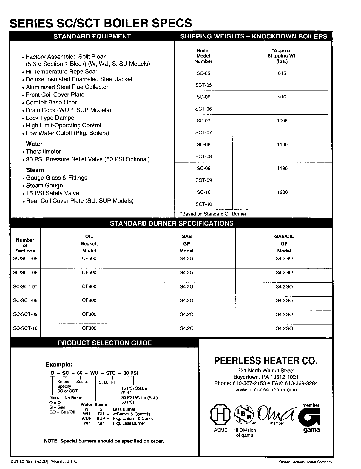
SERIES SC/SCT BOILER SPECS
_.'tl:llll41lUJl'.lll=!lli _[ 17|=l[tllltl |[!l[o[_olol
• Factory Assembled Split Block
(5 & 6 Section t Block) (W, WU, S, SU Models)
• Hi-Temperature Rope Seal
• Deluxe Insulated Enameled Steel Jacket
• Aluminized Steel Flue Collector
• Front Coil Cover Plate
• Cerafelt Base Liner
• Drain Cock (WUP, SUP Models)
• Lock Type Damper
• High Limit-Operating Control
• Low Water Cutoff (Pkg. Boilers)
Water
•Theraltimeter
•30 PSI Pressure Relief Valve (50 PSI Optional)
Steam
• Gauge Glass & Fittings
• Steam Gauge
• 15 PSI Safety Valve
• Rear Coil Cover Plate (SU, SUP Models)
Boiler
Model
Number
SC-05
SCT-05
SC-06
SCT-06
SC-O7
SCT-07
SC-O8
SCT-08
SC-09
SCT-09
SC-10
SCT-10
*Based on Standard Oil Burner
*Approx.
Shipping Wt.
(Ibe.)
815
910
1005
1100
1195
1280
_..'L=-'il = " " " _o1117,,_
OIL GAS GAS/OiL
Number
of Beckett GP GP
Sections Model Model Model
SC/SCT-05 CF500 S4.2G S4.2GO
SC/SCT-06 CF500 $4.2G S4.2GO
SC/SCT-07 CF800 $4.2G S4.2GO
SC/SCT-08 CF800 $4.2G $4.2GO
SC/SCT-09 CF800 $4.2G $4.2GO
SC/SCT-10 CF800 $4.2G $4.2GO
Example:
O - SC - 06- WU -STD - 30PSI
-- T T -- qT
Series Sects. STD, IRI, /
Specify 15 PSI Steam
BC or SCT (Std,)
Blank = No Burner 30 PSI Water (Std.)
O=Oil Water Steam 50 PSI
G=Gas W S =LessBurner
GO =Gas!Oil WU SU = w/Burner& Controls
WUP SUP =Pkg. w/Bum. & Contr.
WP SP = Pkg. LessBurner
NOTE: Special burners should be specified on order.
PEERLESSHEATERC0.
231 North Walnut Street
Boyertown, PA 19512-1021
Phone: 610-367-2153 ,, FAX: 610-369-3284
www.peerless-heater.com
IHD@Ou -"
o_, li
ASME HI Division galTia
o1 gama
cLrr-sc R9 (11/02-3M), printed in USA 02002 Peedess Heater Company

SERIES EC/ECT/SC/SCT
INSTALLATION, OPERATION & MAINTENANCE MANUAL ADDENDUM
FOR INSTALLATION OF PRIMARY PROBE LOW WATER CUT OFF
LIMIT
1 1/2 NPT/
SKIM TAPPING_
0
is
.A C
Figure 1: Rear View
USE TAPPINGS A & C
FOR
APPUCATION
CG450 PROBE
1/2 X 1/2
W/ 1/2 COUPLING
x 3 NIPPLE
TEE
3/4 x 3/4 x 1/4
STEAM GAUGE
w/ 5/4 x 1/4
BUSHINO
_9 1/4" GAUGE GLASS
g
Figure 2: Primary Probe LWCO
Control Location
ALTERNATE
LIMIT/SIPHON
ORIENTATION
IrAqi["_iJ-l[']_l
Do not install a probe low water cut off in the boiler primary probe tapping unless the
low water cut off is equipped with a timed on and off feature. The cycled off time will
allow the probe low water cut off to sense the true water level in the boiler and eliminate
a false reading caused from sensing a foaming or surging water condition. Failure to
use a timed low water cut off could result in a failed heat exchanger.
A - Control Mounting Instructions
NOTE: Longer gauge glass and rods are required for use with the optional CG-450 Primary Probe Low Water Cut Off. The gauge
glass carton, 22-162-10, is provided with a packaged boiler. For a KD boiler the longer gauge glass carton is located in a
special Probe Low Water Cut Off Carton, 90759.
Packaged Boilers: The CG 450P LWCO, and PA404A limit are installed and wired at the factory. The boiler miscellaneous parts
carton, located within the boiler crate, contains the longer gauge glass carton 22-162-10, Gauge Valves Carton 20-105-03, fittings
end components.
KD Boilers: A separate Primary Probe Low Water Cut Off Carton, 90759 is required. This carton contains the CG450 LWCO,
22-162-10 longer glass/rods carton, 3/4" x 3" nipple, 3/4" x 3/4" x 1/4" tee, (2) 1/2" x 2" nipples and (2) 1/2" couplings. Use these
components along with those from the Steam Trim Carton and install fittings and controls per Figure 2.
NOTE: The PA404A limit and siphon are not included as part of a standard KD boiler offering for ECT model boilers.
NOTE: For SCT model boilers, mount controls & steam gauge per Figure 8 in the SC/SCT Installation, Operation & Maintenance
Manual. Install longer gauge glass & fittings per Figure 2 above.
PEEI LESS ®
CAST IRON BOILERS
PEERLESS HEATER COMPANY
231 NORTH WALNUT STREET •BOYERTOWN, PA 19512-1021 •PHONE 610-367-2153
www.peerless-heater.com
THE PREFERRED HEATING CHOICE X8068 R0 (7/02-2.5M)
Printed in U.S.A.
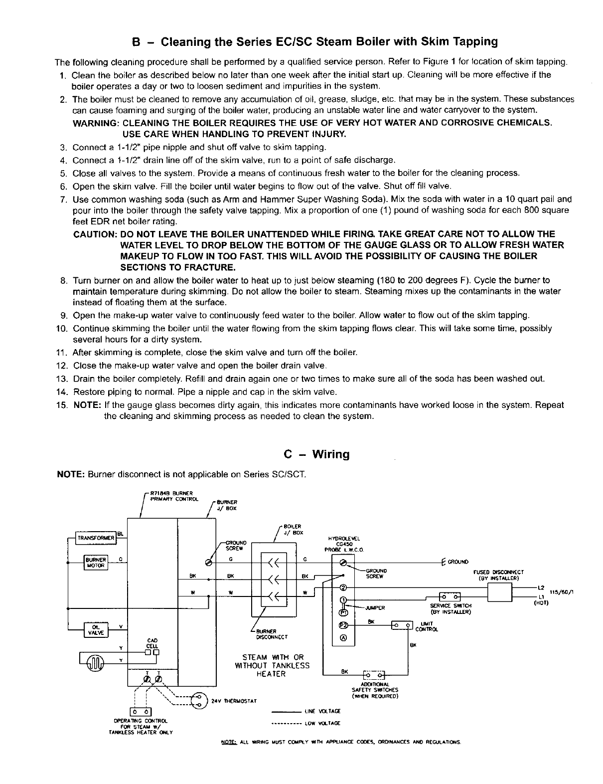
B - Cleaning the Series EC/SC Steam Boiler with Skim Tapping
The following cleaning procedure shall be performed by a qualified service person. Refer to Figure 1 for location of skim tapping.
1. Clean the boiler as described below no later than one week after the initial start up. Cleaning will be more effective if the
boiler operates a day or two to loosen sediment and impurities in the system,
2. The boiler must be cleaned to remove any accumulation of oil, grease, sludge, etc. that may be in the system. These substances
can cause foaming and surging of the boiler water, producing an unstable water line and water carryover to the system.
WARNING: CLEANING THE BOILER REQUIRES THE USE OF VERY HOT WATER AND CORROSIVE CHEMICALS,
USE CARE WHEN HANDLING TO PREVENT INJURY.
3. Connect a 1-1/2" pipe nipple and shut off valve to skim tapping.
4. Connect a 1-1/2" drain line off of the skim valve, run to a point of safe discharge.
5. Close all valves to the system. Provide a means of continuous fresh water to the boiler for the cleaning process.
6. Open the skim valve. Fill the boiler until water begins to flow out of the valve. Shut off fill valve.
7. Use common washing soda (such as Arm and Hammer Super Washing Soda). Mix the soda with water in a 10 quart pail and
pour into the boiler through the safety valve tapping. Mix a proportion of one (1) pound of washing soda for each 800 square
feet EDR net boiler rating.
CAUTION: DO NOT LEAVE THE BOILER UNATTENDED WHILE FIRING, TAKE GREAT CARE NOT TO ALLOW THE
WATER LEVEL TO DROP BELOW THE BOTTOM OF THE GAUGE GLASS OR TO ALLOW FRESH WATER
MAKEUP TO FLOW IN TOO FAST. THIS WILL AVOID THE POSSIBILITY OF CAUSING THE BOILER
SECTIONS TO FRACTURE.
8. Turn burner on and allow the boiler water to heat up to just below steaming (180 to 200 degrees F). Cycle the burner to
maintain temperature during skimming. Do not allow the boiler to steam. Steaming mixes up the contaminants in the water
instead of floating them at the surface.
9. Open the make-up water valve to continuously feed water to the boiler. Allow water to flow out of the skim tapping.
10. Continue skimming the boiler until the water flowing from the skim tapping flows clear. This will take some time, possibly
several hours for a dirty system.
11. After skimming is complete, close the skim valve and turn off the boiler.
12. Close the make-up water valve and open the boiler drain valve.
13. Drain the boiler completely. Refill and drain again one or two times to make sure all of the soda has been washed out.
14. Restore piping to normal. Pipe a nipple and cap in the skim valve.
15. NOTE: If the gauge glass becomes dirty again, this indicates more contaminants have worked loose in the system. Repeat
the cleaning and skimming process as needed to clean the system.
C - Wiring
NOTE: Burner disconnect is not applicable on Series SC/SCT.
Y
R7184B BURNER /
pRIMARy CONTROL BURNER
J/ BOX
BOILER
J/ BOX
G¢
BK LBK BK
W
CA{) Ol$C_l [¢
[] STEAM WITH OR
WITHOUT TANKLESS
/HEATER
I/" I _Y ", •
1 "_ .... o_ _4V 1M[RMOSTAT
OPERATING CONTROL
FOr( 5TEAM W/
TANKLESS H£ATER ONLY
H YDROLE _IEL
CG450
(BY INST_LU.£R)
--JUMPER )_£R'_ SIq TCH
(BY INSTALLER)
SAFETY SMTQdES
-- LIN[ VOLTAG[
.......... tOW VOLTA_
ALt _MRING MUST COMPty _T_I APPLIANOE COOLS, ORDINANCES AN0 R[GULATIONS
INSTALLATIONINSTRUCTIONS- SERIESSCandSCT
Readcarefullybeforebeginningwork.Itwillsavetime.Studythe includeddrawings.
Theequipmentshallbe installedin accordancewiththoseinstallationregulationsinforceinthe localareawherethe installationis to be
made.Theseshall becarefullyfollowedin al!cases.Authoritieshavingjurisdictionshallbe consultedbeforeinstallationsare made,
A-ACCESSIBILITYCLEARANCES
1-- To providefor reasonableconditionsof accessibilityfor servicing,the followingminimumclearancesarerecommendedbetweenthe
boilerand adjacentwallsorotherappliances--24"onthe rightside, 36"on the leftside,and30" inthefrontandrearof the boiler.
B-AIR FORCOMBUSTIONANDVENTILATION
1-- Becertainadequatefacilitiesareavailableto provideairfor satisfactorycombustionandventilation,
2-- AppliancesLocatedin UnconfinedSpaces.
a. Installationsin unconfinedspaceswithconventionalconstructionandlargeareassuchas basements,the supplyof airfor
combustionandventilationcan usuallybeconsideredadequate.
3-- ApplianceLocatedinConfinedSpaces
a. If allair for combustionandventilationis to comefromwithinthe building;twoopenings,onenearthe ceilingandonenearthe
floorof the boilerroomshall beprovidedwiththe minimumfreeareaof each openingequalto 140sq.in. pergallonof oilburned.
b. If allairfor combustionand ventilationis to comefrom outsidethe building;two openings,onenearthe ceilingandonenearthe
floorof the boilerroomshall beprovidedwiththe minimumfreeareaof each openingequalto 35sq. in.pergallonof oil burned.
Ifductsareusedtoconveytheair,areasof 35sq.in. pergallonofoilburnedforverticalductsor70sq.in.pergallonof oilburnedfor
horizontalductsareto beprovided.Ductsshallhavethe sameareaasthefreeareaof theopeningstowhichtheyareconnected.
C-SETrlNGUP BOILER
1-- ModelsSC/SCT-05andSC/SCT-06areshippedina singleblock.Theboilersectionson modelsSC/SCT-07thruSC/SCT-10are
shippedintwo parts.
2-- Providea goodlevelfoundation,locatedas closeas possibleto the centerof the heatingsystemandto the chimneyorventsystem.
The heatingsurfaceof theSC/SCTSeriesBoilersisdesignedto becleanedfromeitherthetop or leftofthe unit.Allowadequate
clearanceon the leftof unit if servicingisto bedonefromthe side.
CAUTION'.THISBOILERIS NOTAPPROVEDFORUSEON COMBUSTIBLEFLOORING.
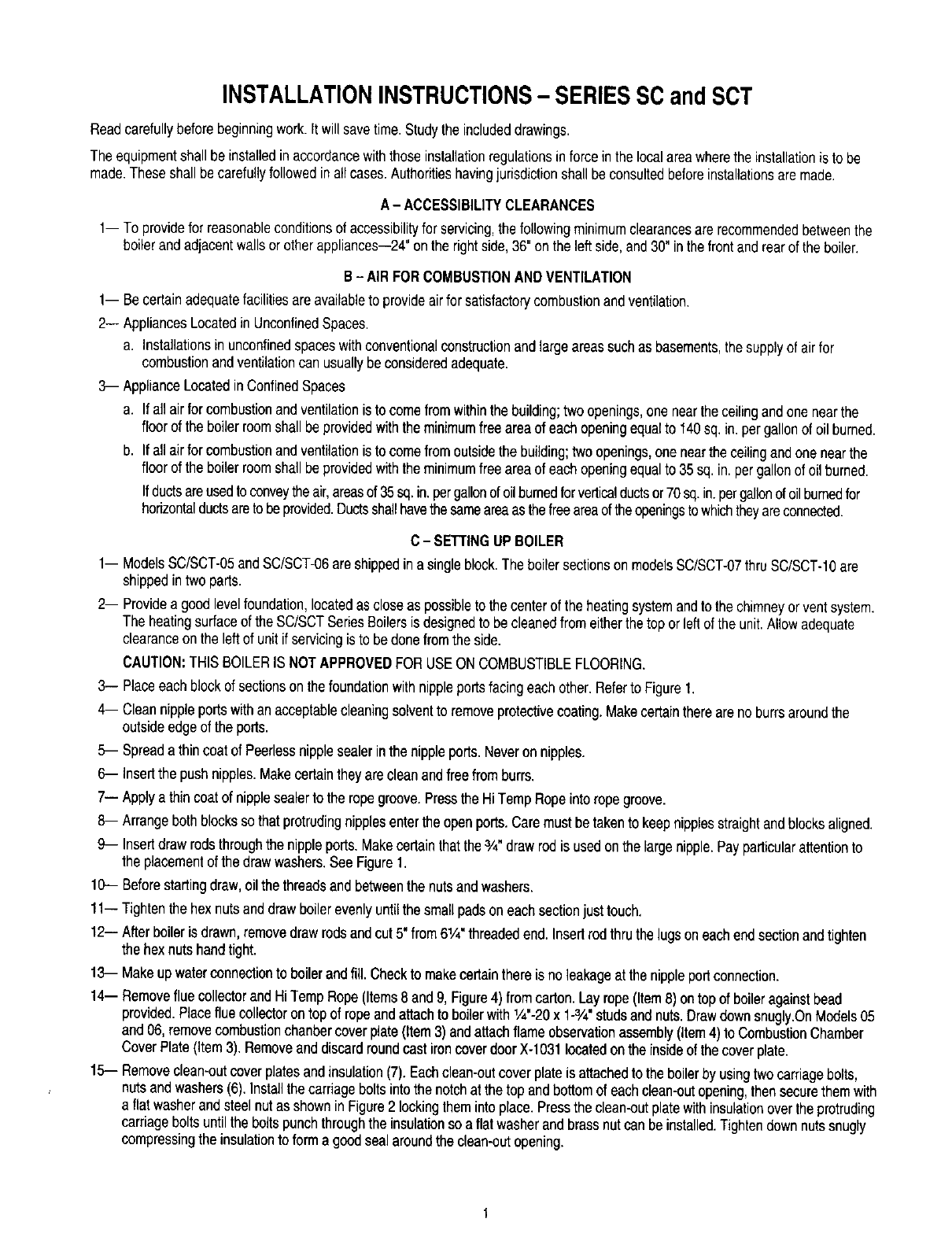
3-- Placeeachblockof sectionson thefoundationwithnippleportsfacingeachother.RefertoFigure1.
4-- Cleannippleportswithanacceptablecleaningsolventto removeprotectivecoating.Makecertaintherearenoburrsaroundthe
outsideedgeof the ports.
5-- Spreada thincoatof Peerlessnipplesealerinthe nippleports.Neveron nipples.
6-- Insertthe pushnipples.Makecertaintheyarecleanandfreefromburrs.
7-- Applya thin coatof nipplesealerto the ropegroove.Pressthe Hi TempRopeinto ropegroove.
8-- Arrangebothblockssothat protrudingnipplesentertheopenports.Caremustbetakento keepnipplesstraightandblocksaligned.
9-- Insertdrawrodsthroughthe nippleports.Makecertainthatthe3/4"draw rodis usedonthe largenipple.Payparticularattentionto
the placementof the drawwashers.SeeFigure1.
10-- Beforestartingdraw,oilthe threadsandbetweenthe nutsandwashers.
11-- Tightenthe hexnutsanddrawboilerevenlyuntilthe smallpadson eachsectionjusttouch,
12-- Afterboileris drawn,removedrawrodsandcut5" from6!/4"threadedend. Insertrodthruthe lugson eachendsectionandtighten
the hexnutshandtight.
13- Makeupwaterconnectiontoboilerandfill. Checkto makecertainthere isnoleakageat the nippleportconnection.
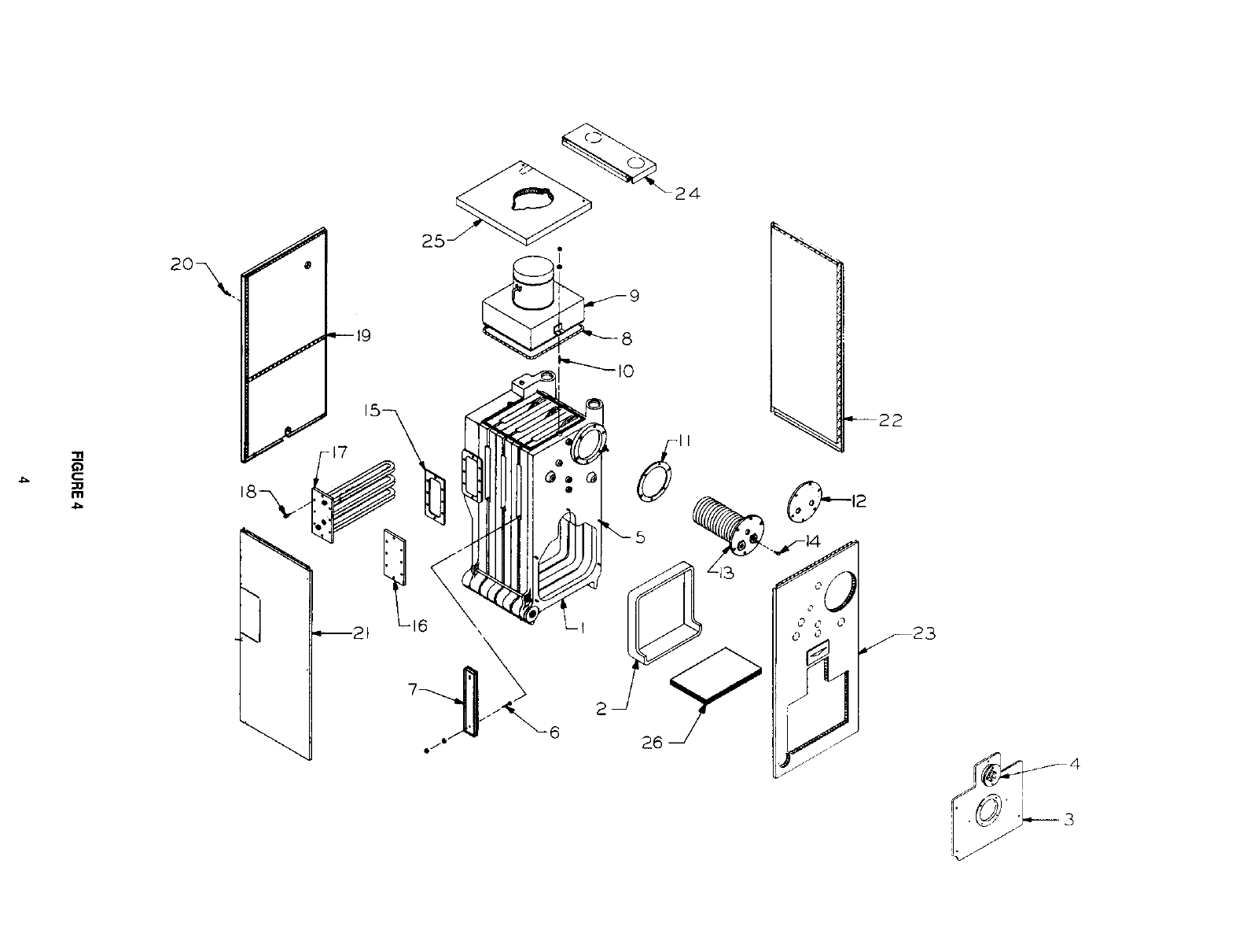
14-- Removeflue collectorandHi TempRope(Items8 and9, Figure4) fromcarton.Lay rope(Item8) ontopof boileragainstbead
provided.Placefluecollectorontopof ropeandattachto boilerwith1/4"-20x 1-3/4"studsandnuts.Drawdownsnugly.OnModels05
and06, removecombustionchanbercoverplate(Item3)andattachflameobservationassembly(item4)to CombustionChamber
CoverPlate(item3). Removeanddiscardroundcast ironcoverdoorX-1031locatedonthe insideof the coverplate.
15- Removeclean-outcoverplatesandinsulation(7). Eachclean-outcoverplateis attachedto the boilerby usingtwocarriagebolts,
nutsandwashers(6).Installthecarriageboltsintothe notchat the top andbottomof eachclean-outopening,thensecurethemwith
a flatwasherandsteelnutas shownin Figure2 lockingtheminto place.Pressthe clean-outplatewith insulationoverthe protruding
carriageboltsuntilthe boltspunchthroughthe insulationso a flatwasherandbrassnutcan beinstalled.Tightendownnutssnugly
compressingthe insulationto forma goodseal aroundthe clean-outopening.
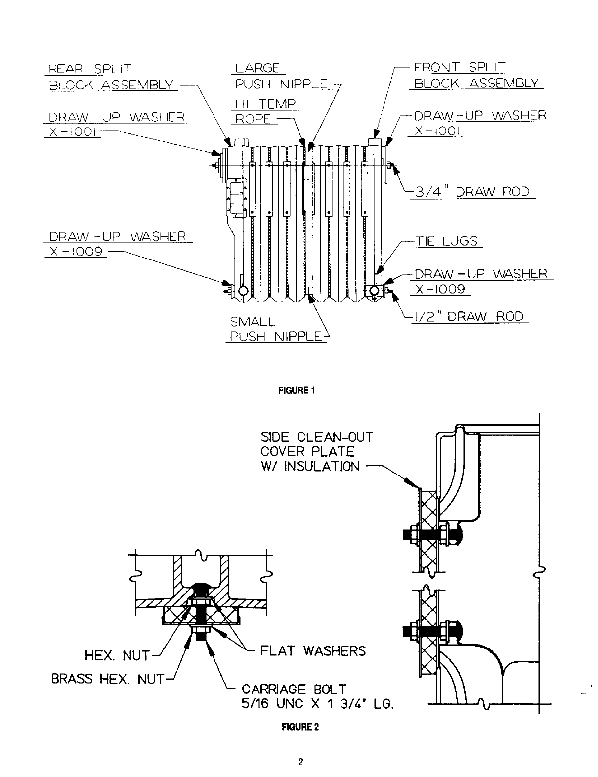
REAR SPLIT LARGE
BLOCK ASSEMBLY _ PUSH NIPPLE
\HI TEMP
DRAW-UP WASHER \ ROPE
FRONT SPLIT
BLOCK ASSEMBLY
)RAW-UP WASHER
X -100t
3/4" DRAW ROD
DRAW-UP WASHER
X - 1009
SMALL
PUSH NIPPLE _
LUGS
- UP WASHER
X - 1009
I/2" DRAW ROD
FIGUREI
SIDE CLEAN-0UT
COVER PLATE
W/INSULATION
HEX.
BRASS HEX. NUT
FLAT WASHERS
CARRIAGE BOLT
5/16 UNO X 1 3/4." Le.
FIGURE2
x
2
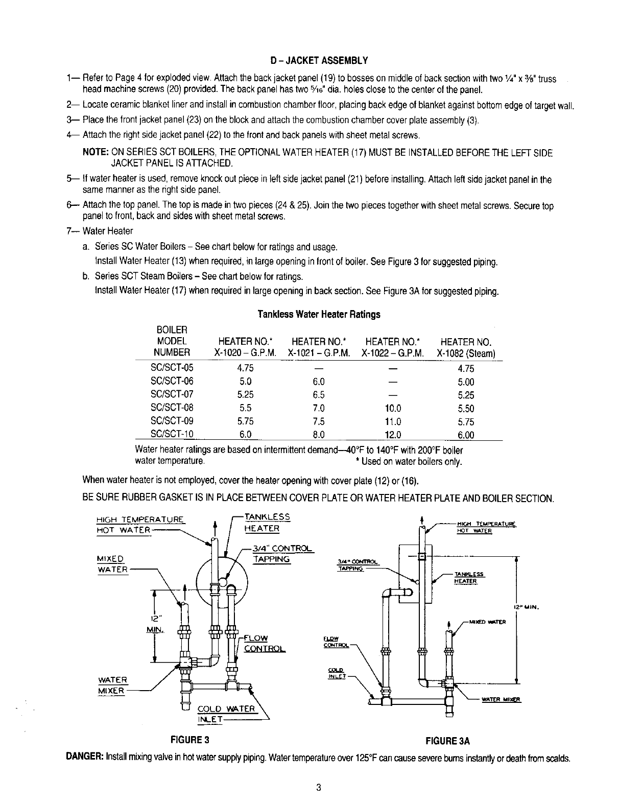
D-JACKETASSEMBLY
1-- Referto Page4 for explodedview.Attachthe backjacketpanel(19)to bossesonmiddleof backsectionwithtwo1.4"x %"truss
headmachinescrews(20)provided.The backpanelhas two%0"dia. holescloseto the centerof the panel.
2-- Locateceramicblanketlinerandinstallincombustionchamberfloor,placingbackedgeof blanketagainstbottomedgeoftargetwall.
3-- Placethefrontjacketpanel(23)onthe blockandattachthecombustionchambercoverplateassembly(3).
4-- Attachthe rightsidejacket panel(22)to thefrontandbackpanelswithsheetmetalscrews.
NOTE:ONSERIESSCTBOILERS,THEOPTIONALWATERHEATER(17)MUSTBEINSTALLEDBEFORETHELEFTSIDE
JACKETPANELISATTACHED.
5-- Ifwaterheateris used,removeknockout pieceinleftsidejacketpanel(21)beforeinstalling.Attachleftsidejacketpanelinthe
samemanneras the rightside panel.
6-- Attachthe top panel.The top is madein twopieces(24& 25).Jointhe twopiecestogetherwithsheetmetalscrews.Securetop
panelto front,backandsideswithsheetmetalscrews.
7-- WaterHeater
a. SeriesSC WaterBoilers- Seechartbelowfor ratingsandusage.
InstallWaterHeater(13)when required,inlargeopeninginfrontof boiler.SeeFigure3for suggestedpiping.
b. SeriesSCTSteamBoilers- Seechartbelowfor ratings.
InstallWaterHeater(17)when requiredinlargeopeninginbacksection.SeeFigure3Afor suggestedpiping.
TanklessWaterHeaterRatings
BOILER
MODEL HEATERNO.* HEATERNO.* HEATERNO.* HEATERNO.
NUMBER X-1020-G.PM. X-1021-G.P.M X-1022-G.P.M X-1082(Steam)
SC/SCT-05 4.75 -- -- 4.75
SC/SCT-06 5.0 6.0 -- 5.00
SC/SCT-07 5.25 6.5 -- 5.25
SC/SCT-08 5.5 7.0 10.0 5.50
SC/SCT-09 5.75 7.5 11.0 5.75
SC/SCT-10 6.0 8.0 12.0 6.00
Waterheaterratingsarebasedonintermittentdemand--40°Fto 140°Fwith200°Fboiler
watertemperature. * Usedonwaterboilersonly.
Whenwaterheateris not employed,coverthe heateropeningwithcoverplate(12)or (16).
BESURERUBBERGASKETIS IN PLACEBETWEENCOVERPLATEOR WATERHEATERPLATEANDBOILERSECTION.
HIGH TEMPERATURE _ _M_R_U_
HOT WATER_ HEATER _T _E
MIXED TAPPING _4,,oo_moL
WATER
MIXER
CONTROL
FIGURE3 FIGURE3A
DANGER:Installmixingvalveinhotwatersupplypiping.Watertemperatureover125°Fcancauseseverebumsinstantlyordeathfromscalds.
___.
:10
\1
2
626
"---22

SERIESSC/SCT
Item No. Description PartNo. SCiSCT-05SCiSCT-06SCiSCT-07
1BlockAssembly- SC-05ModelOnly X-1096 X
BlockAssembly- SC-06ModelOnly X-1096-1 X
BlockAssembly- SCT-05ModelOnly X-1097 X
BlockAssembly- SCT-06ModelOnly X-1097-1 X
FrontSplitBlockAssembly SC-1018 X
FrontSplitBlockAssembly SC-1018-1
BackSplitBlockAssembly SC-1019 X
BackSplitBlockAssembly SC-1019-1
BackSplitBlockAssembly SC-1019-2
BackSplitBlockAssembly(SCTModel) SC-1020 X
BackSplitBlockAssembly(SCTModel) SC-1021-1
BackSplitBlockAssembly(SCTModel) SC-1021-2
2 TargetWall X-3019 X X X
3 CombustionChamberCoverPlate X-1060-1 X X X
4 FlameObservationAssembly SC-1012 X X X
5 5/16"-18x 2-1/4"Studsw/Nuts- 5 Req'd X-1061 X X X
6 5/16"-18x 1-3/4"CarriageBoltw/Nut X X X
7 SideClean-OutCoverPlate X-1085 X X X
8 HighTemp.Rope1/2"Dia.64"Long X
HighTemp.Rope1/2"Dia.72"Long X
HighTemp.Rope1/2"Dia.80"Long X
HighTemp.Rope1/2"Dia.88"Long
HighTemp.Rope1/2"Dia.96"Long
HighTemp.Rope1/2"Dia.104"Long
9 FlueCollectorandDamperAssembly SC-5005-5 X
FlueCollectorandDamperAssembly SC-5005 X
FlueCollectorandDamperAssembly SC-5005-1 X
FlueCollectorandDamperAssembly SC-5005-2
FlueCollectorandDamperAssembly SC-5005-3
FlueCollectorandDamperAssembly SC-5005-4 I
10 1/4"-20x 1-3/4"Studsw/Nuts- 2 Req'd X-5000 X X X
11 RubberGasket X-1023 X X ....._' X
_._ CoverPlate X-1059 X X X
TanklessCoil(OptionalWaterOnly) X-1020 X X ':, X
TanklessCoil(OptionalWaterOnly) X-1021 X ! X
t
_TanklessCoil(OptionalWaterOnly) X-1022 i
14 3/8"-16x 3/4"HexHd.CapScrews- 6 Req'd X X X
15 RubberGasket(SCTModels) X-1083 X x , x
16 CoverPlate(SCTModels) X-1084 _ X X : X
17 I TanklessHeater(OptionalSCTModels) X-1082 X i X I X
18 [3/8"-16x3/4"HexHd. CapScrews -X X X
(SCTModels)- 8 Req'd
19 Ba[Back------------_acke!Panel SC-6003_ X _ X _ X
ModelNo.
SC,/SCT.-_
X
X
X
X
X
X
X
x
X
X
X
X
X
X
X
X
X
X
X
X
SCiSCT..09
x
X
X
X
X
X
X
X
X
X
X
X
X
i X
! X
i
F
iX
X
;X
X
X
X
X
SC_-IO
x
x
X
X
X
X
X
X
X
X
X
X
X
X
X
X
X
X
X
X
X
X
XXX
5
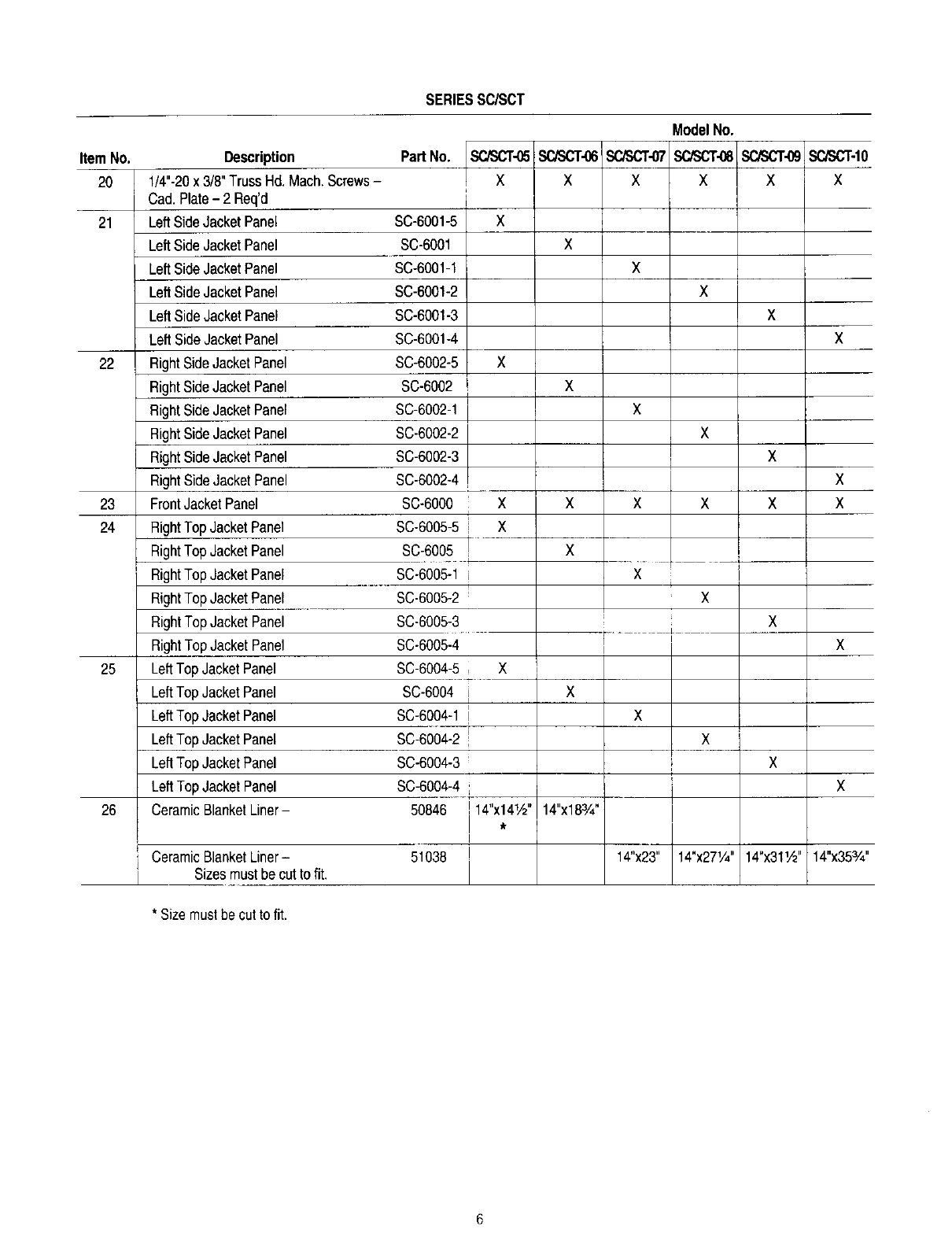
SERIESSC/SCT
ModelNo.
Item No. Part No. SCiSCT-05SC/SCT-06SCiSCT-07 SC/SCT-10
20 XXX X
21 X
X
X
X
22 X
X
23 X X
i
24 iX
X
i
i
X
X
ix x
X
Description
1/4"-20x 3/8" TrussHd.Mach.Screws-
Cad.Plate- 2 Req'd
LeftSideJacketPanel
LeftSideJacketPanel
LeftSideJacketPanel
LeftSideJacketPanel
LeftSideJacketPanel
LeftSideJacketPanel
RightSideJacketPanel
RightSideJacketPanel
RightSideJacketPanel
RightSideJacketPanel
RightSideJacketPanel
RightSideJacketPanel
FrontJacketPanel
RightTopJacketPanel
RightTopJacketPanel
RightTopJacketPanel
RightTopJacketPanel
RightTopJacketPanel
RightTopJacketPane]
LeftTop JacketPanel
LeftTop JacketPanel
LeftTop JacketPanel
LeftTop JacketPanel
LeftTop JacketPanel
LeftTopJacketPanel
CeramicBlanketLiner-
SC-6001-5
SC-6001
SC-6001-1
SC-6001-2
SC-6001-3
SC-6001-4
SC-6002-5
SC-6002
SC-6002-1
SC-6002-2
SC-6002-3
SC-6002-4
SC-6000
SC-6005-5
SC-6005
SC-6005-1
SC-6005-2
SC-6005-3
SC-6005-4
SC-6004-5
SC-6004
SC-6004-1
SC-6004-2
SC-6004-3
SC-6004-4
50846
I
25 , X
i X
l
! x
26 14"x18%"! 14"x141/2"
I
I
,CeramicBlanketLiner- 51038
I Sizesmustbe cattofit. 14"x23"
SCPaCT..08SOSOT..09
X X
X
X
X
X
X X
IX
X
I
X
X
14"x271/4' 14"x311/2'
X
x
14"x35%"
*Sizemustbecutto fit.
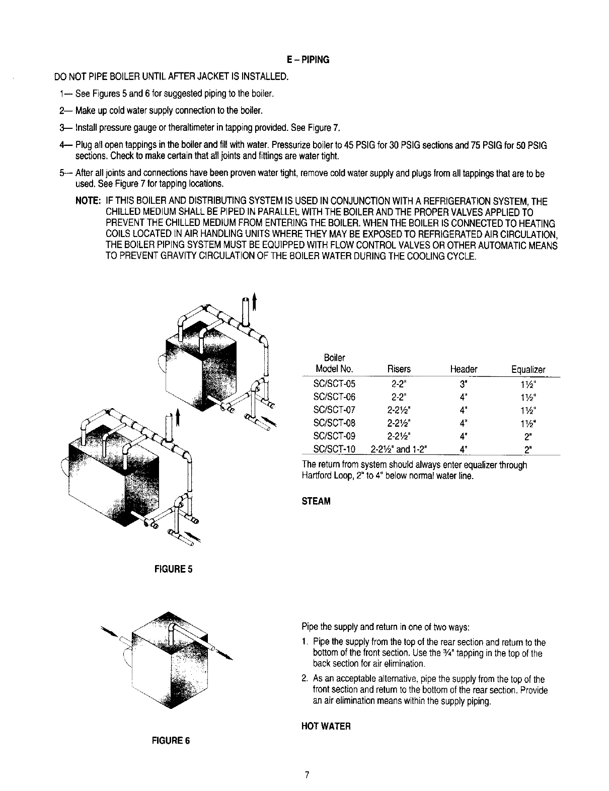
E-PIPING
DONOTPIPEBOILERUNTILAFTERJACKETIS INSTALLED.
1-- See Figures5 and6for suggestedpipingto the boiler.
2-- Makeupcoldwatersupplyconnectionto the boiler.
3-- Installpressuregaugeor theraltimeterintappingprovided.SeeFigure7.
4-- Plugall opentappingsinthe boilerandfill withwater.Pressurizeboilerto 45 PSIGfor 30 PSIGsectionsand75 PSIGfor 50 PSIG
sections.Checkto makecertainthat alljointsandfittingsare watertight.
5-- Afteralljointsandconnectionshavebeenprovenwatertight,removecoldwatersupplyandplugsfromalltappingsthatareto be
used.SeeFigure7 for tappinglocations.
NOTE: IFTHISBOILERANDDISTRIBUTINGSYSTEMIS USEDINCONJUNCTIONWITHA REFRIGERATIONSYSTEM,THE
CHILLEDMEDIUMSHALLBEPIPEDIN PARALLELWITHTHEBOILERANDTHEPROPERVALVESAPPLIEDTO
PREVENTTHECHILLEDMEDIUMFROMENTERINGTHEBOILER.WHENTHEBOILERIS CONNECTEDTO HEATING
COILSLOCATEDINAIR HANDLINGUNITSWHERETHEYMAYBEEXPOSEDTO REFRIGERATEDAIRCIRCULATION,
THEBOILERPIPINGSYSTEMMUSTBEEQUIPPEDWITHFLOWCONTROLVALVESOR OTHERAUTOMATICMEANS
TO PREVENTGRAVITYCIRCULATIONOFTHEBOILERWATERDURINGTHECOOLINGCYCLE.
Boiler
ModelNo. Risers Header Equalizer
SC/SCT-05 2-2" 3" 11_"
SC/SCT-06 2-2" 4" 1W'
SC/SCT-07 2-21/2" 4" l_.&"
SC/SCT-08 2-21/2" 4" 11/2"
SC/SCT-09 2-21/2" 4" 2"
SC/SCT-IO 2-21,_' and 1-2" 4" 2"
The returnfromsystemshouldalwaysenterequalizerthrough
HartfordLoop,2"to 4" belownormalwaterline.
STEAM
FIGURE5
FIGURE6
Pipethesupplyandreturninoneof twoways:
1. Pipethe supplyfromthe topof the rearsectionandreturnto the
bottomof thefrontsection.Usethe3/4"tappingin thetop of the
backsectionfor airelimination.
2. As an acceptablealternative,pipethe supplyfromthetop of the
frontsectionandreturnto the bottomof the rearsection.Provide
an aireliminationmeanswithinthe supplypiping.
HOTWATER
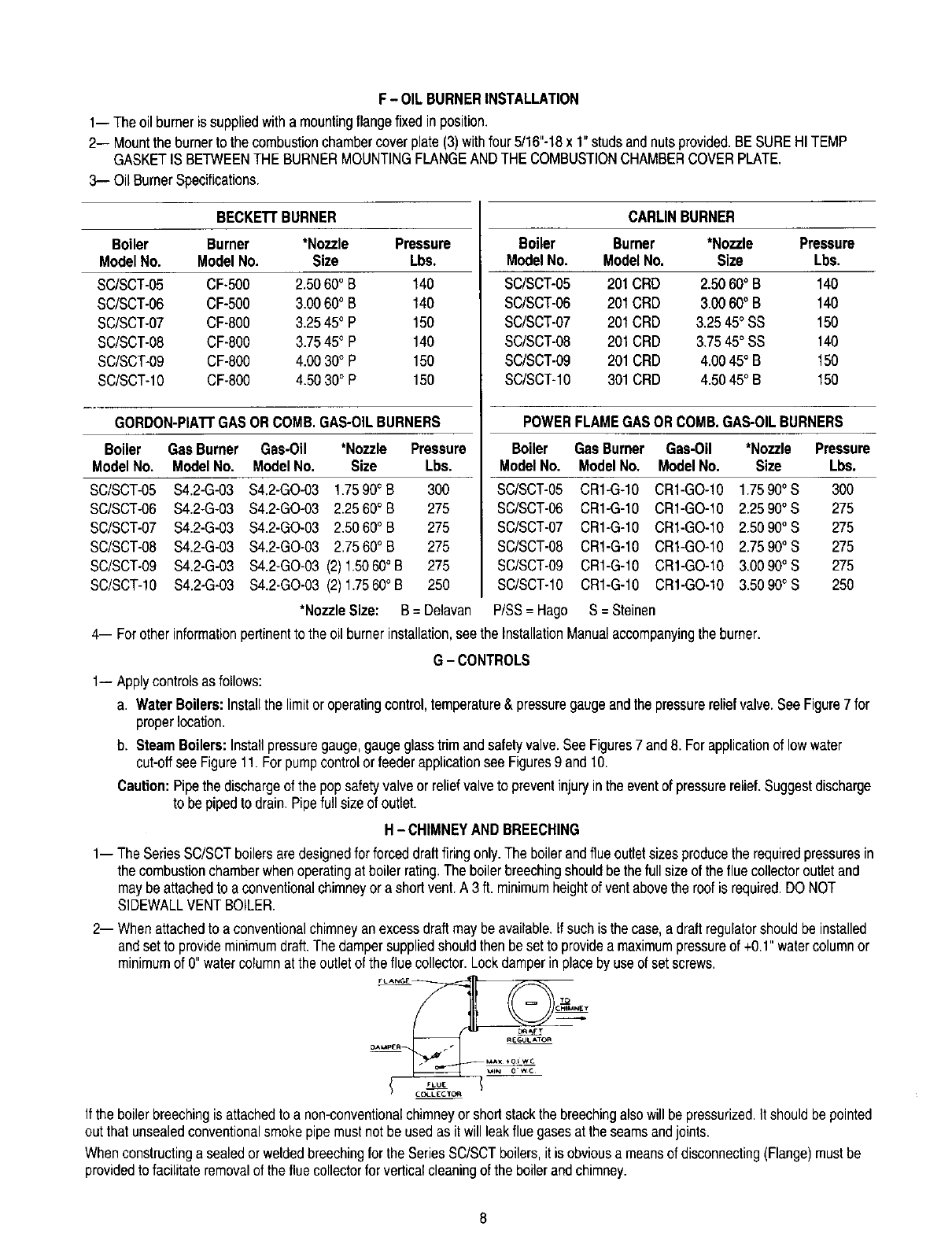
F-OIL BURNERINSTALLATION
1-- Theoilburneris suppliedwithamountingflangefixedinposition.
2-- Mountthe burnerto the combustionchambercoverplate(3)withfour5/16"-18x1"studsandnutsprovided.BE SUREHITEMP
GASKETIS BETWEENTHE BURNERMOUNTINGFLANGEANDTHECOMBUSTIONCHAMBERCOVERPLATE.
3-- OilBurnerSpecifications.
BECKE'n'BURNER CARLINBURNER
Boiler Burner *Nozzle Pressure
ModelNo. ModelNo. Size Lbs.
SC/SCT-05 CF-500 2.5060° B140
SC/SCT-06 CF-500 3.00600B 140
SC/SCT-07 CF-800 3.25450P 150
SC/SCT-08 CF-800 3.7545° P 140
SC/SCT-09 CF-800 4.00 30° P 150
SC/SCT-10 CF-800 4.50 30° P 150
Boiler Burner *Nozzle Pressure
ModelNo, ModelNo, Size Lbs,
SC/SCT-05 201CRD 2.5060°B 140
SC/SCT-06 201CRD 3.00600B 140
SC/SCT-07 20t CRD 3.2545°SS 150
SC/SCT-08 201 CRD 3.7545° SS 140
SC/SCT-09 201CRD 4.0045° B 150
SC/SCT-10 301CRD 4.5045° B 150
GORDON-PIAI-rGASOR COMB.GAS-OILBURNERS POWERFLAMEGASORCOMB.GAS-OILBURNERS
Boiler GasBurner Gas-Oil *Nozzle Pressure
ModelNo. ModelNo. ModelNo. Size Lbs.
SC/SCT-05 $4.2-G-03 $4,2-GO-03 1.7590° B 300
SC/SCT-06 $4.2-G-03 $4.2-GO-03 2.2560° B 275
SC/SCT-07 $4.2-G-03 $4.2-GO-03 2.5060° B 275
SC/SCT-08 $4.2-G-03 $4.2-GO-03 2.7560° B 275
SC/SCT-09 $4.2-G-03 $4.2-GO-03 (2) 1.5060° B 275
SC/SCT-10 $4.2-G-03 $4.2-GO-03 (2) 1.7560° B 250
*NozzleSize: B = Delavan
Boiler GasBurner Gas-Oil *Nozzle Pressure
ModelNo. ModelNo, ModelNo. Size Lbs.
SC/SCT-05 CR1-G-10 CR1-GO-10 1.75900S300
SC/SCT-06 CR1-G-10 CR1-GO-10 2.2590°S 275
SC/SCT-07 CR1-G-10 CR1-GO-10 2.5090°S 275
SC/SCT-08 CR1-G-10 CR1-GO-10 2.7590° S 275
SC/SCT-09 CR1-G-10 CR1-GO-10 3.0090°S 275
SC/SCT-10 CR1-G-10 CR1-GO-10 3.50900S 250
P/SS= Hago S= Steinen
4-- Forother informationpertinentto the oil burnerinstallation,seethe InstallationManualaccompanyingthe burner.
G-CONTROLS
1- Applycontrolsasfollows:
a. WaterBoilers:Installthe limitor operatingcontrol,temperature& pressuregaugeandthe pressurereliefvalve.SeeFigure7 for
properlocation.
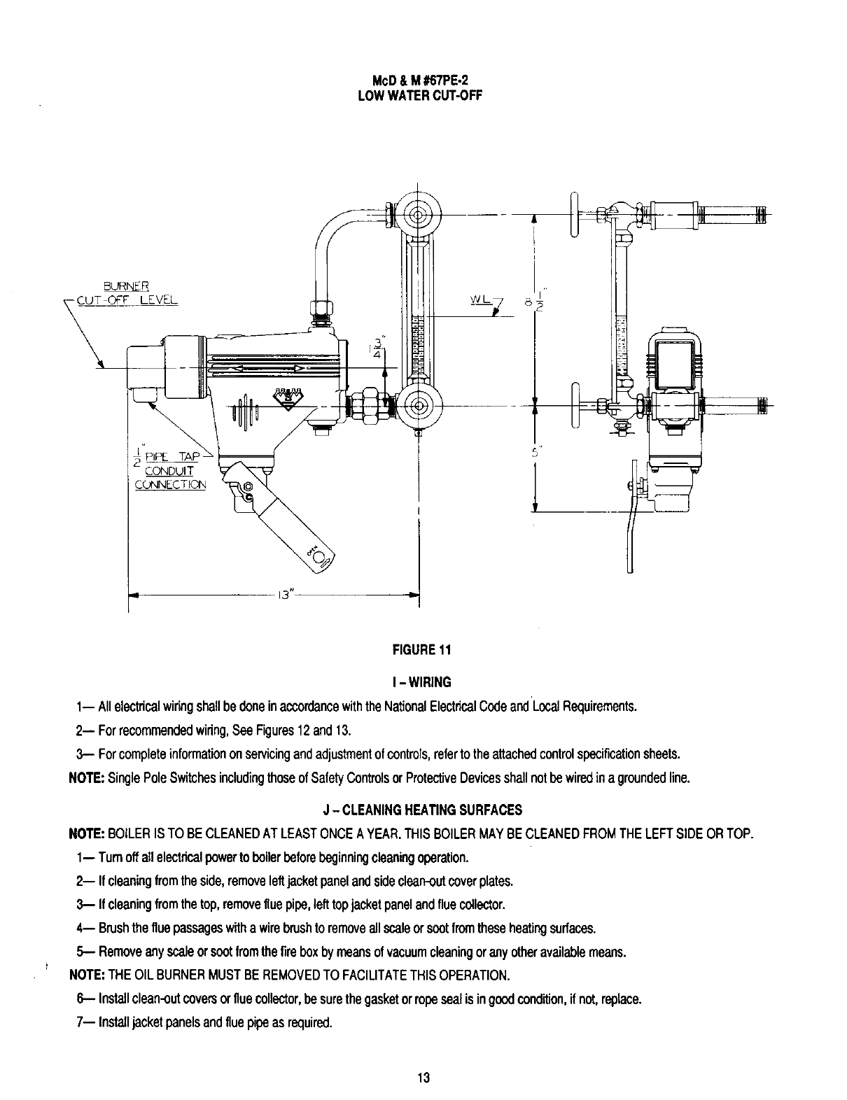
b. SteamBoilers:Installpressuregauge,gaugeglasstrim andsafetyvalve.SeeFigures7 and8. For applicationof lowwater
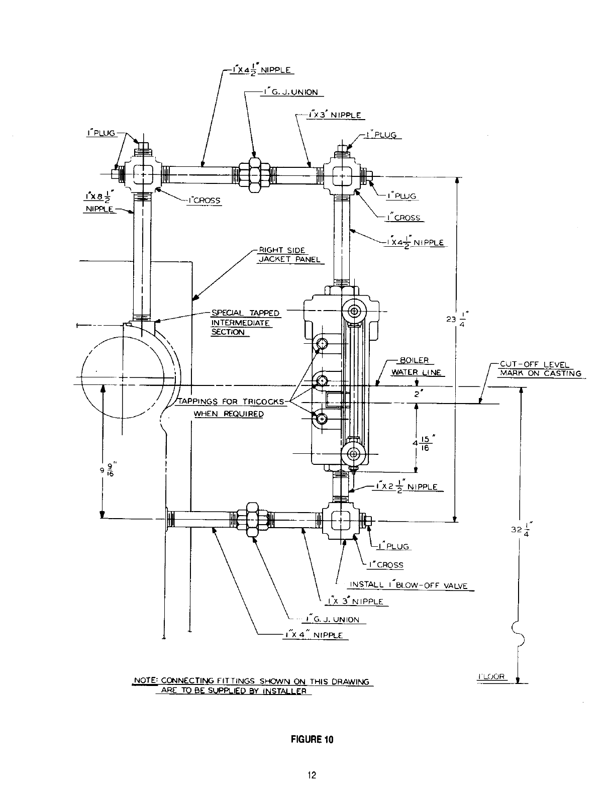
cut-oftsee Figure11. Forpumpcontrolor feederapplicationsee Figures9 and10.
Caution: Pipethe dischargeof the popsafetyvalveor reliefvalveto preventinjuryinthe eventof pressurerelief.Suggestdischarge
to bepipedto drain.Pipefull sizeof outlet.
H-CHIMNEYANDBREECHING
1- The SeriesSC/SCTboilersaredesignedforforceddraftfiringonly.The boilerandflue outletsizesproducethe requiredpressuresin
the combustionchamberwhen operatingat boilerrating.The boilerbreechingshouldbethefull sizeof theflue collectoroutletand
maybe attachedto aconventionalchimneyor a shortvent.A 3 ft. minimumheightof ventabovethe roofis required.DONOT
SIDEWALLVENTBOILER.
2-- Whenattachedto a conventionalchimneyanexcessdraftmaybeavailable.If suchis the case,adraftregulatorshouldbeinstalled
andsetto provideminimumdraft.The dampersuppliedshouldthen besetto providea maximumpressureof +0.1"watercolumnor
minimumof 0" watercolumnat the outletof the fluecollector.Lockdamperin placebyuse of setscrews.
_ _AFT
DA_pEF I R£_ULATOR
MAX *0_ We
CC_LECT_
Ifthe boilerbreechingis attachedto a non-conventionalchimneyor shortstackthe breechingalsowill bepressurized.It shouldbe pointed
outthat unsealedconventionalsmokepipemustnotbe usedas it will leakflue gasesat theseamsandjoints.
Whenconstructinga sealedor weldedbreechingfor theSeriesSC/SCTboilers,it is obviousa meansof disconnecting(Flange)mustbe
providedto facilitateremovalof the flue collectorfor verticalcleaningof the boilerandchimney.
8
FRONT
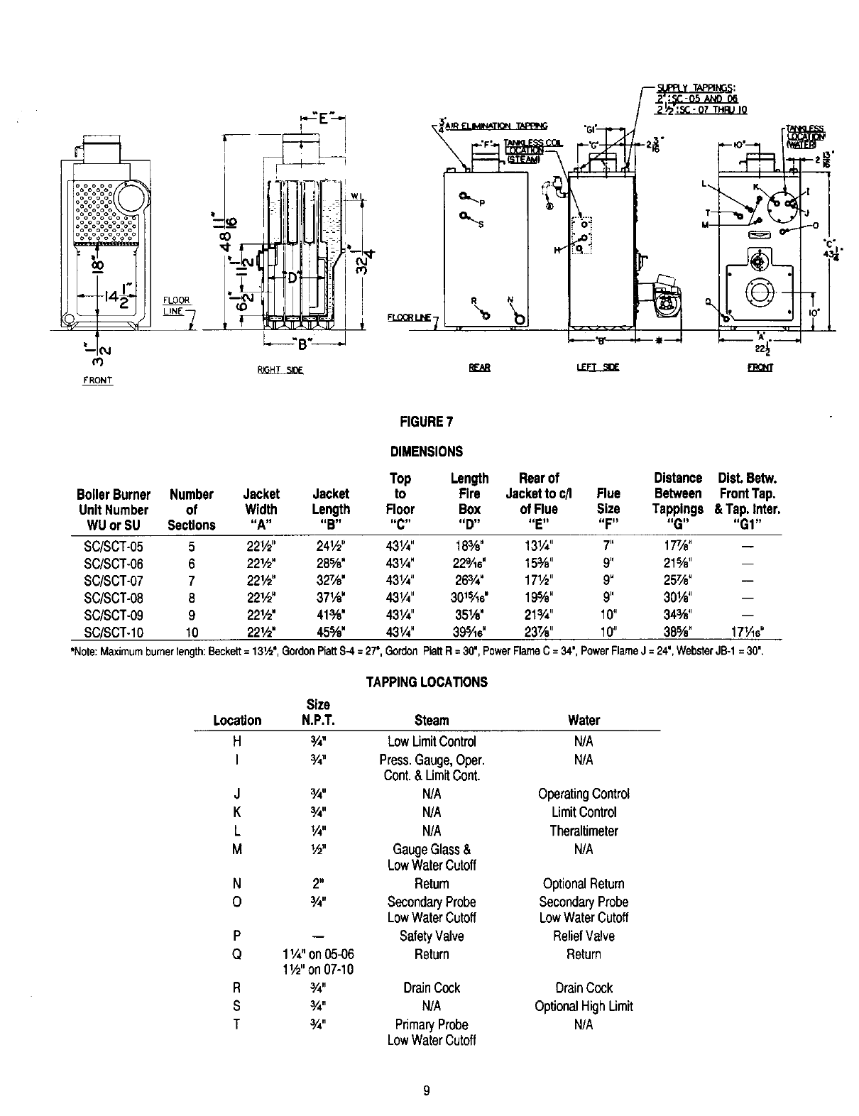
FIGURE7
DIMENSIONS
Top Length Rearof
BoilerBurner Number Jacket Jacket to Fire Jacketto c/I
Unit Number of Width Length Floor Box of Flue
WUorSU Sections "A .... B.... C.... D.... E"
SC/SCT-05 5 221/2" 24r/2" 431/_" 18%" 131/4"
SC/SCT-06 6 221/2" 28%" 431/4" 22%e" 15%"
SC/SCT-07 7 22!._" 327/8" 43!/4" 26¾" 171/2"
SC/SCT-08 8 221,_" 371/_" 43!/4" 301S/is' 19%"
SC/SCT-09 9 221/2" 41%" 431/4' 35Ve" 213/._'
SC/SCT-IO 10 221/2" 45%" 43";/4" 39sAe" 23Ve"
Distance Dist.Betw.
Flue Between FrontTap.
Size Tappings & Tap.Inter.
"F.... G.... GI"
7" 17_" --
9" 21%" --
9" 257/e" --
9" 30W' --
10" 34¾" --
10" 38%" 171,_e"
*Note:Maximum burnerlength:Beckett= 131,,_",GordonPiatt$4 = 27",Gordon Piatt R = 30", Power FlameC =34", PowerFlameJ =24', WebsterJB-1 =30",
Size
Location N.P.T.
H¾"
I¾"
J¾"
K
L
M
N
0
P
Q
R
S
T
TAPPINGLOCATIONS
Steam Water
LowLimitControl N/A
Press.Gauge,Oper. N/A
Cont.& LimitCont.
N/A OperatingControl
¾" N/A LimitControl
I,_" N/A Theraltimeter
W' GaugeGlass& N/A
LowWaterCutoff
2" Return OptionalReturn
¾" SecondaryProbe SecondaryProbe
LowWaterCutoff LowWaterCutoff
-- SafetyValve ReliefValve
1V4"on05-06 Return Return
1W' on 07-10
¾" DrainCock DrainCock
¾" N/A OptionalHighUmit
¾" PrimaryProbe N/A
LowWaterCutoff
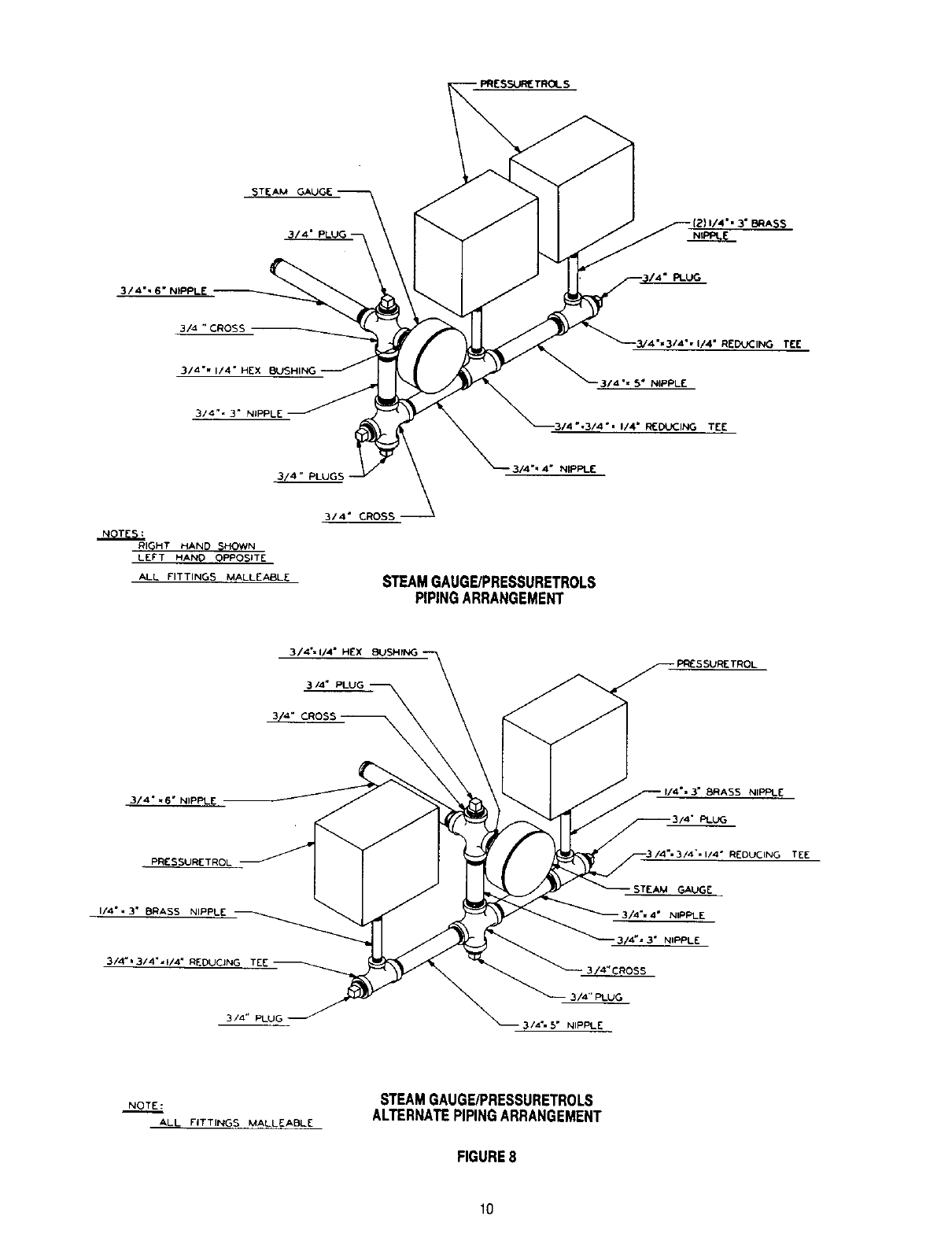
STEAM
3/4"
3/4" PLUGS
NOTES.'
RIGHT HAND SHOWN
LEFT HAND OPPOSITE
ALL FITTINGS MALLEABLE
314 °" 4" NIPPLE
STEAMGAUG_PRESSURETROLS
PIPINGARRANGEMENT
PLUG
REDUCING TEE
3/4", S" NIPPLE
3/4"11/4 °HEX BUSHING
3/4 °
CROSS
314",6 ° NIPPLE
PRESSURETROL
I/4",3 ° BRASS NIPPLE
314"=3/4"°W4" REDUCING TEE
3/4" PLUG
=EDUCING TEE
STEAM GAUGE
3/4%4" NIPPLE
--3/4"° 3" NIPPLE
3/4"CR0SS
3/4"PLUG
3/_=5" NIPPLE
NOTE:
ALL FITTINGS MALLEABLE
STEAMGAUGE/PRESSURETROLS
ALTERNATEPIPINGARRANGEMENT
FIGURE8
10
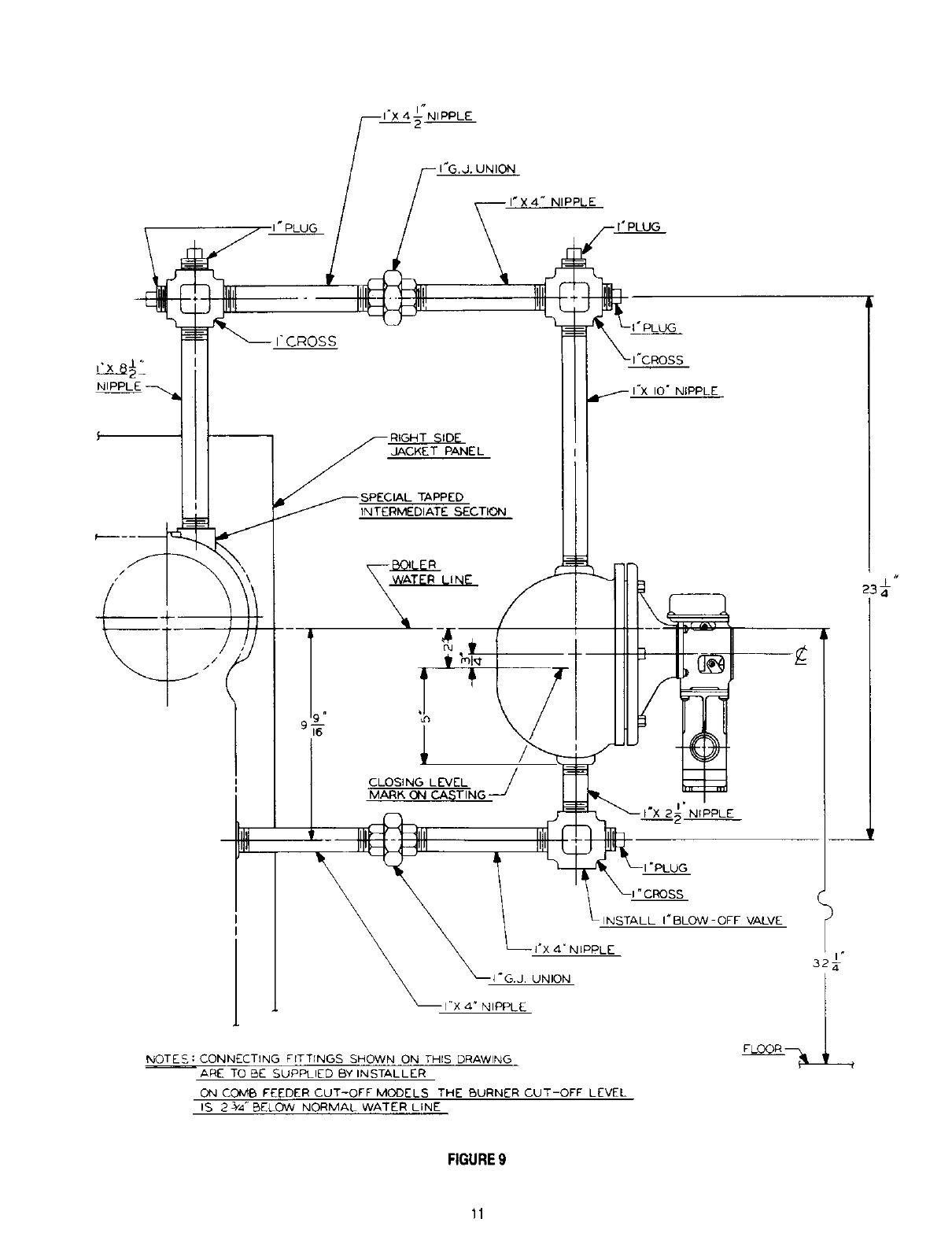
NIPPLE
I'CROSS
• . UNION
I
Illl
IIq
JACKET PANEL
,PECIAL TAPPED
INTERMEDIATE SECTION
S
"x IO" NIPPLE
INSTALL I'BLOW-OFF VALVE
I*x ,4" N _PI::'LE
UNION
NOTES:CONNECTING FITTINGS SHOWN ON THIS DRAWING
ARE TO BE SUPPLIED BY INSTALLER
ON COMB FEEDER CUT-OFF MODELS THE BURNER CUT-OFF LEVEL
IS 23/4 " BELOW NORMAL WATER LINE
FLOOR
#
FIGURE9
11
IPPLE
LEVEL
MARA ON CASTING
r,
INSTALL I_IBLOW-OF'F VALVE
I"X 3" NIPPLE
I"G. J. UNION
I"X 4" NIPPLE
NOTE: CONN_CTING FITTINGS SHOWN ON THIS DRAWING
ARE T_ E)_ SUPPLIED BY INSTALLER
FIGURE10
12
McD& M #67PE-2
LOWWATERCUT-OFF
B_
-CUT _F LEVEL WL
PIPE
CONNECTION
FIGURE11
I - WIRING
1-- Allalectricalwiringshallbe doneinaccordancewiththeNationalElectricalCedeandLocalRequirements.
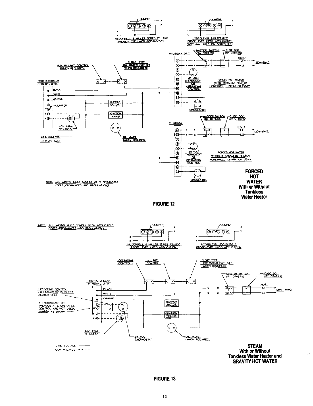
2-- Forrecommendedwiring,See Figures12and13.
3-- Forcompleteinformationonservicingandadjustmentofcontrols,refertotheattachedcontrolspecificationsheets.
NOTE:SinglePoleSwitchesincludingthoseofSafetyControlsorProtectiveDevicesshallnotbewiredin a groundedline.
J - CLEANINGHEATINGSURFACES
NOTE:BOILERISTO BECLEANEDATLEASTONCEAYEAR.THISBOILERMAYBECLEANEDFROMTHELEFTSIDEORTOP.
1-- Turnoffallelectricalpowertoboilerbeforebeginningcleaningoperation.
2-- If cleaningfromtheside,removeleftjacketpanelandsideclean-outcoverplates.
3-- If cleaningfromthetop,removeflue pipe,lefttopjacketpanelandfluecollector.
4-- Brushthe fluepassageswitha wirebrushto removeallscaleorseatfromtheseheatingsurfaces.
5.-- Removeanyscaleorsootfromthefireboxbymeansofvacuumcleaningorany otheravailablemoans.
NOTE:THEOILBURNERMUSTBEREMOVEDTO FACILITATETHISOPERATION.
6-- Installolean-outcoversorfluecollector,besurethegasketorropesealisingoodcondition,if not,replace.
7-- Installjacketpanelsandflue pipeas required.
13
HY C_ EVIL. G_O'P/_0 "P
1_6C-Typ_ LWCO Ap'_._.KTK_*_
cm
r_ ..........
LOW V_L T_E ....
_ALL WIRING k_T (_fq_y TH APP_I_J_J_LE
,r--
-v--
-- q:_)
@.__
_WiTH TA_LESS _ATI:R
@
OR_ULA_
1::©
FORCED
HOT
WATER
Withor Without
Tankless
WaterHeater
FIGURE12
_O_" S, CRDIk_ANC£ S. ANO _-_
M(-IJO_N_t • & MILLER _Rlr_ p'_-_
_-TYF_ L_K_O r_PPLk'_ATION HyOR_EVC,_L 650- W5_O -p
_LOW "/#AT T- F
W_IT[ _ X--X LI "_ V _ 5OH?. `
__ _ __ _
WithorWithout
TanklessWaterHeaterand
GRAV/TYHOTWATER .k.
FIGURE13
14
UnitNumber
BoilerBurner
WUorSU
SC/SCT-05
SC/SCT-06
SC/SCT-07
SC/SCT-08
SC/SCT-09
SC/SCT-10
Gross
I=B=R
Output
M.B.H.
343
405
462
519
575
632
Water_
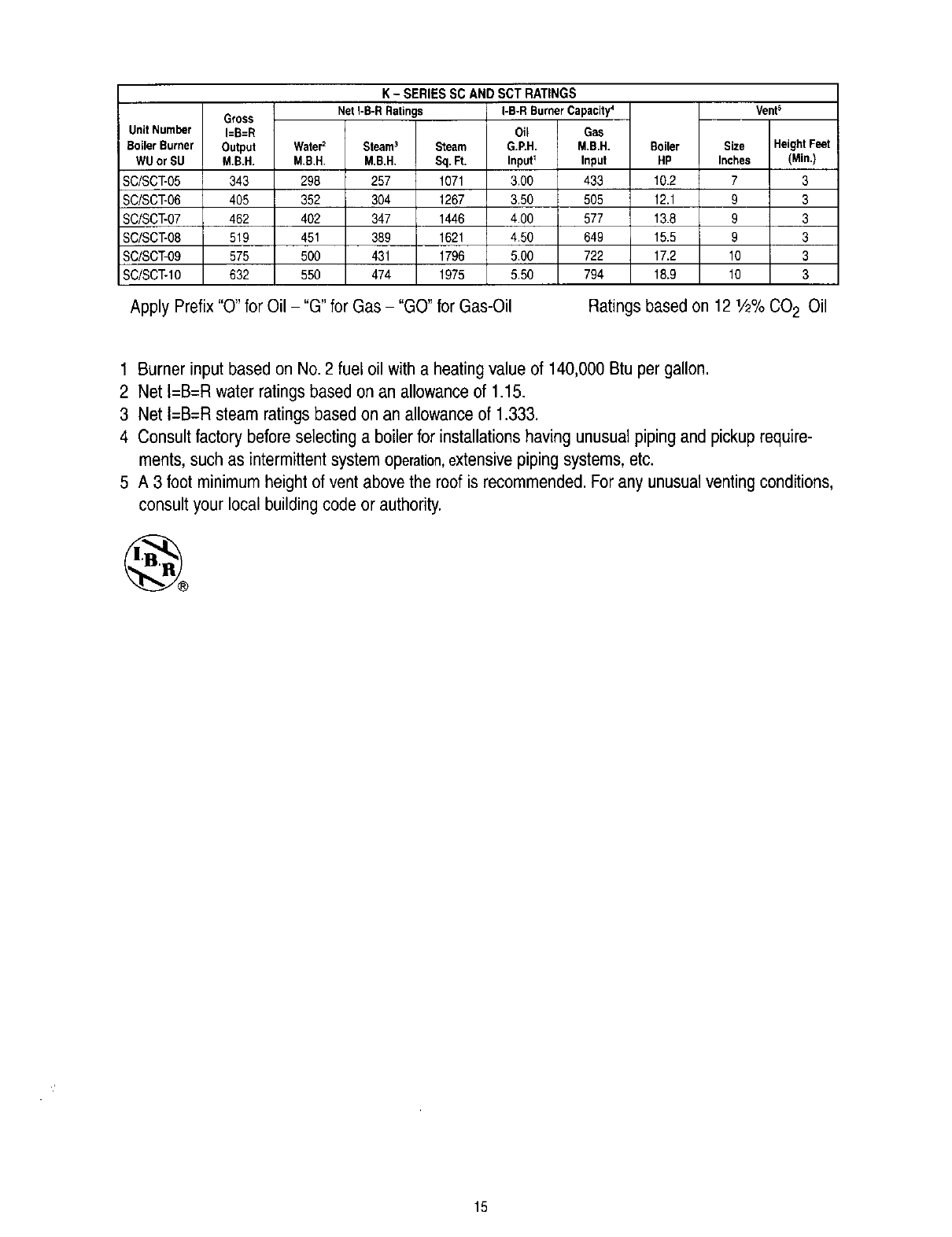
K - SERIES SC AND SCT RATINGS
Net I-B-R Ratings I-B-R Burner Capacity4
Oil Gas
Steam3Steam G.P.H. M,B.H. Boiler Inches
7
9
9
9
10
10
M.B.H, M.B.H,
298 257
352 304
402 347
451 389
500 431
550 474
Sq.R. Input_Input
1071 3.00 433
1267 3.50 505
1446 4.00 577
1621 4.50 649
1796 5.00 722
1975 5.50 794
HP
10.2
12.1
13.8
15.5
17.2
18.9
VenP
Size HeightFeet
(Min.)
3
3
3
3
3
3
Apply Prefix"O" for Oil - "G"for Gas - "GO"for Gas-Oil Ratings based on 12 1/2%CO 2 Oil
1 Burner input based on No.2 fuel oil with a heating value of 140,000 Btu per gallon.
2 Net I=B=R water ratings based on an allowanceof 1.15.
3 Net i=B=R steam ratings based on an allowanceof 1.333.
4 Consult factory before selecting a boilerfor installations having unusual piping and pickup require-
ments, such as intermittent system operation,extensivepiping systems, etc.
5 A 3 foot minimum height of vent above the roof is recommended.For any unusual venting conditions,
consult your local building code or authority.
15

Series SC/SCT
Oil, Gas 8 Gas/Oil Boilers
Installation,
Operation r:
Maintenance
Manual
TO THE INSTALLER:
This manual is the property of the owner and must
be affixed near the boiler for future reference.
TO THE OWNER:
This boiler should be inspected annually by a
Qualified Service Agency,
_ _ O_ Gmember
member gama
PEERLESS"
CAST IRON BOILERS
PEERLESS HEATER COMPANY
231 NORTH WALNUT STREET •BOYERTOWN, PA 19512-1021 •PHONE 610-367-2153
www.peerless-heater corn
THE PHEFEHRED HEATING CHOICE
©2002 Peerless Heater Company SC8000 R9 (6/02-2M)
Printed in U.S.A.
