PEGATRON CMST173 IEEE 802.11b/g/n Wireless LAN Module (Single Antenna) User Manual
PEGATRON CORPORATION IEEE 802.11b/g/n Wireless LAN Module (Single Antenna)
PEGATRON >
User manual

AW-NU173
IEEE 802.11 b/g/n WLAN Wireless Module
User’s Manual

I. Introduction
i. Overview
AzureWave Technologies, Inc. introduces the first IEEE 802.11b/g/n WLAN module Card
-AW-NU173. By using AW-NU173, the customers can easily enable the Wi-Fi embedded
applications with the benefits of high design flexibility, short development cycle, and quick
time-to-market.
Compliance with the IEEE 802.11b/g/n standard, the AW-NU173 uses Direct Sequence Spread
Spectrum (DSSS), Orthogonal Frequency Division Multiplexing (OFDM), DBPSK, DQPSK, CCK and
QAM baseband modulation technologies. A high level of integration and full implementation of
the power management functions specified in the IEEE 802.11 standard minimize the system
power requirements by using AW-NU173. In addition to the support of WPA/WPA2 and WEP
64-bit and 128-bit encryption, the AW-NU173 also supports the IEEE 802.11i security standard
through the implementation of Advanced Encryption Standard (AES)/Counter Mode CBC-MAC
Protocol (CCMP), Wired Equivalent Privacy (WEP) with Temporal Key Integrity Protocol (TKIP),
Advanced Encryption Standard (AES)/Cipher-Based Message Authentication Code (CMAC), and
WLAN Authentication and Privacy Infrastructure (WAPI) security mechanisms.
For the video, voice and multimedia applications the AW-NU173 support 802.11e Quality of
Service (QoS).
The AW-NU173 supports USB for WLAN to the host processor.
ii. Features
USB interfaces support for WLAN
Multiple power saving modes for low power consumption
IEEE 802.11i for advanced security
Quality of Service (QoS) support for multimedia applications
iii. Product Review
1. Connection Mode
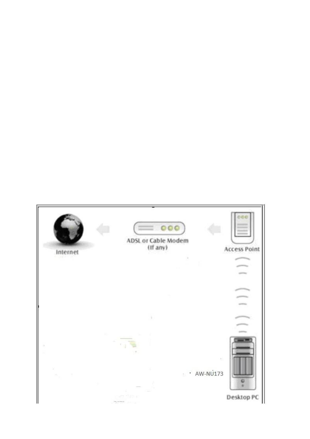
◎Infrastructure Mode
Infrastructure mode needs an access point to establish the network, which can provide wireless
accesses within valid range for users to communicate with others or transmit data with a wired
network. There are several benefits of Infrastructure networking:
√ Roaming: a wireless LAN enabled computer can physically move from the operating range of one
access point to the other without losing connection. There is a quick association made between
new access point and wireless device as the computer traverses from the coverage of one access
point to another.
√ Range Extension: each wireless LAN enabled computer within the range of access point can
communicate with other wireless LAN enabled computers within the effective range from the
access point.
√ Wired to wireless LAN connection: the access point will establish a bridge between wireless LAN
and other wired counterparts.
Infrastructure Mode
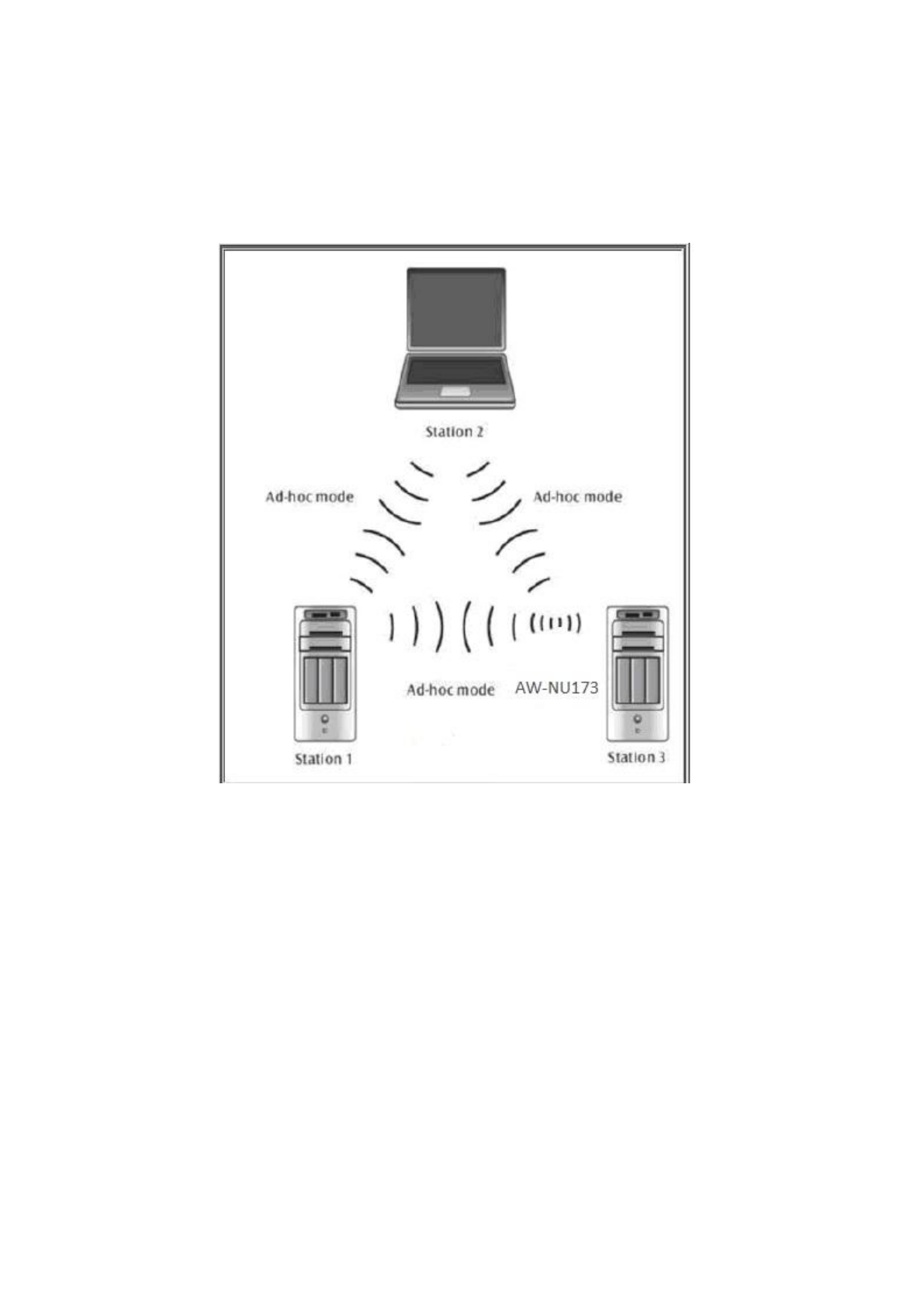
◎Ad-hoc Mode
The difference between Ad-hoc mode and Infrastructure mode is that Ad-hoc mode does not need
the access point or router. When you use this mode, your computer will act as a server within the
valid range and connect directly to others in the same LAN workgroup.
Ad-hoc Mode
It is recommended to choose this mode when there is no access point showed on your wireless
network.
1. Initial Command
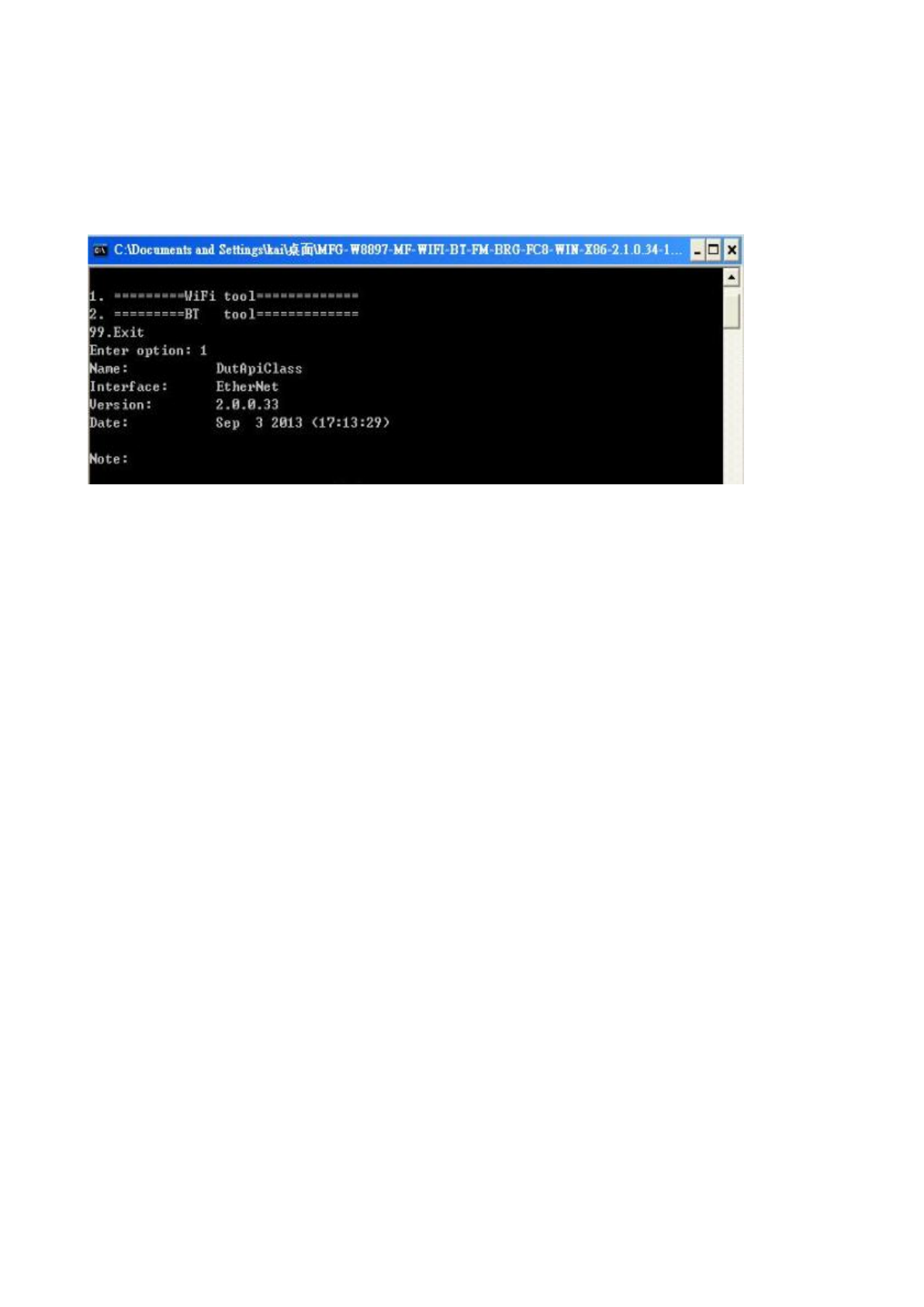
i. RF Tx/Rx Performance Test
As the information showed on your screen, please enter these commands below to start your test.
(Figure 3)
Command: 1 Wi-Fi testing
Figure 3
Generate 802.11a/b/g/n Packet commands
a. Tx on CH 1 at 17 dBm with a CCK-11Mbps data rate in 20 MHz BW mode on path A
10 1 1 // Set Path A Only
112 0 // Set to 20 MHz BW
22 1 17 0 // Set to CH 1 at 17dBm Output Power with CCK/BPSK Data Rate on Path A
25 1 4 // Tx at 11 Mbps
25 0 // Stop Tx
------------------------------------------------------------------------------------------------------------------------------
b. Tx on CH 1 at 17 dBm with a CCK-11Mbps data rate in 20 MHz BW mode on path B
10 0 0 // Set Path B Only
112 0 // Set to 20 MHz BW
22 1 17 0 // Set to CH 1 at 17dBm Output Power with CCK/BPSK Data Rate on Path B
25 1 4 // Tx at 11 Mbps
25 0 // Stop Tx
------------------------------------------------------------------------------------------------------------------------------
c. Tx on CH 6 at 12 dBm with a MCS7 Data rate in 40 MHz BW Mode on Path A
10 1 1 // Set Path A
112 1 // Set to 40 MHz BW
22 6 12 1 // Set to CH6 at 12dBm Output Power with OFDM Data Rate on path A
25 1 22 // Tx at MCS 7
25 0 // Stop Tx
------------------------------------------------------------------------------------------------------------------------------

Data rate set up
B mode & G mode:
1Mbps
5.5Mbps
11Mbps
6Mbps
9Mbps
12Mbps
18Mbps
24Mbps
1
3
4
6
7
8
9
10
36Mbps
48Mbps
54Mbps
11
12
13
N mode:
MCS0
MCS1
MCS2
MCS3
MCS4
MCS5
MCS6
MCS7
15
16
17
18
19
20
21
22
After you type above command, you can measure the 802.11b/g/n packet by your RF test instrument (exp:
Agilent 4010, IQview…).
Generate 802.11b/g/n continuous symbol Commands
a. Cont. Tx on CH 7 at 12 dBm with a MCS7 Data rate in 20 MHz BW Mode on Path A
10 1 1 // Set Path A
112 0 // Set to 20 MHz BW
22 7 12 1 // Set to CH7 at 12 dBm Output Power with OFDM Data Rate on Path A
17 1 22 // Cont. Tx at MCS7
17 0 // Stop Cont. Tx
1.5 Test RX sensitivity Commands
a. Rx on CH 7 in 20 MHz BW Mode on both Path A
25 // Stop Tx
10 1 1 // Set to Path A
112 0 // Set to 20 MHz BW
12 7 // Set to CH 100
31 // Clear all the received packets
32 // Get Rx Packet Count and then clear the Rx packet counter
1.6 Others Commands
(1) Command 45
(2) Command 99

Federal Communication Commission Interference Statement
This device complies with Part 15 of the FCC Rules. Operation is subject to the following two conditions: (1)
This device may not cause harmful interference, and (2) this device must accept any interference received,
including interference that may cause undesired operation.
This equipment has been tested and found to comply with the limits for a Class B digital device, pursuant to
Part 15 of the FCC Rules. These limits are designed to provide reasonable protection against harmful
interference in a residential installation. This equipment generates, uses and can radiate radio frequency
energy and, if not installed and used in accordance with the instructions, may cause harmful interference to
radio communications. However, there is no guarantee that interference will not occur in a particular
installation. If this equipment does cause harmful interference to radio or television reception, which can
be determined by turning the equipment off and on, the user is encouraged to try to correct the
interference by one of the following measures:
- Reorient or relocate the receiving antenna.
- Increase the separation between the equipment and receiver.
- Connect the equipment into an outlet on a circuit different from that
to which the receiver is connected.
- Consult the dealer or an experienced radio/TV technician for help.
FCC Caution: Any changes or modifications not expressly approved by the party responsible for compliance
could void the user's authority to operate this equipment.
This transmitter must not be co-located or operating in conjunction with any other antenna or transmitter.
Radiation Exposure Statement:
This equipment complies with FCC radiation exposure limits set forth for an uncontrolled environment. This
equipment should be installed and operated with minimum distance 20cm between the radiator & your
body.
This device is intended only for OEM integrators under the following conditions:
1) The antenna must be installed such that 20 cm is maintained between the antenna and users, and
2) The transmitter module may not be co-located with any other transmitter or antenna.
As long as 2 conditions above are met, further transmitter test will not be required. However, the OEM
integrator is still responsible for testing their end-product for any additional compliance requirements
required with this module installed
IMPORTANT NOTE: In the event that these conditions can not be met (for example certain laptop
configurations or co-location with another transmitter), then the FCC authorization is no longer considered
valid and the FCC ID can not be used on the final product. In these circumstances, the OEM integrator will

be responsible for re-evaluating the end product (including the transmitter) and obtaining a separate FCC
authorization.
End Product Labeling
This transmitter module is authorized only for use in device where the antenna may be installed such that
20 cm may be maintained between the antenna and users. The final end product must be labeled in a
visible area with the following: “Contains FCC ID: VUI-CMST173”. The grantee's FCC ID can be used only
when all FCC compliance requirements are met.
Manual Information To the End User
The OEM integrator has to be aware not to provide information to the end user regarding how to install or
remove this RF module in the user's manual of the end product which integrates this module.
The end user manual shall include all required regulatory information/warning as show in this manual.
This radio transmitter (AW-NU173 if Category II) has been approved by Industry Canada to operate with the
antenna types listed below with the maximum permissible gain and required antenna impedance for each
antenna
type indicated. Antenna types not included in this list, having a gain greater than the maximum
gain indicated for that type, are strictly prohibited for use with this device.
Antenna model number: Canon, Antenna Type:PCB , Gain 2.52dBi, Impedance 50 ohms

Industry Canada statement:
This device complies with RSS-210 of the Industry Canada Rules. Operation is subject to the following two
conditions: (1) This device may not cause harmful interference, and (2) this device must accept any
interference received, including interference that may cause undesired operation.
Ce dispositif est conforme à la norme CNR-210 d'Industrie Canada applicable aux appareils radio exempts
de licence. Son fonctionnement est sujet aux deux conditions suivantes: (1) le dispositif ne doit pas
produire de brouillage préjudiciable, et (2) ce dispositif doit accepter tout brouillage reçu, y compris un
brouillage susceptible de provoquer un fonctionnement indésirable.
Radiation Exposure Statement:
This equipment complies with IC radiation exposure limits set forth for an uncontrolled environment. This
equipment should be installed and operated with minimum distance 20cm between the radiator & your
body.
Déclaration d'exposition aux radiations:
Cet équipement est conforme aux limites d'exposition aux rayonnements IC établies pour un
environnement non contrôlé. Cet équipement doit être installé et utilisé avec un minimum de 20 cm de
distance entre la source de rayonnement et votre corps.
This device is intended only for OEM integrators under the following conditions: (For module device use)
1) The antenna must be installed such that 20 cm is maintained between the antenna and users, and
2) The transmitter module may not be co-located with any other transmitter or antenna.
As long as 2 conditions above are met, further transmitter test will not be required. However, the OEM
integrator is still responsible for testing their end-product for any additional compliance requirements
required with this module installed.
Cet appareil est conçu uniquement pour les intégrateurs OEM dans les conditions suivantes: (Pour
utilisation de dispositif module)
1) L'antenne doit être installée de telle sorte qu'une distance de 20 cm est respectée entre l'antenne et les
utilisateurs, et
2) Le module émetteur peut ne pas être coïmplanté avec un autre émetteur ou antenne.
Tant que les 2 conditions ci-dessus sont remplies, des essais supplémentaires sur l'émetteur ne seront pas
nécessaires. Toutefois, l'intégrateur OEM est toujours responsable des essais sur son produit final pour
toutes exigences de conformité supplémentaires requis pour ce module installé.
IMPORTANT NOTE:
In the event that these conditions can not be met (for example certain laptop configurations or co-location
with another transmitter), then the Canada authorization is no longer considered valid and the IC ID can
not be used on the final product. In these circumstances, the OEM integrator will be responsible for
re-evaluating the end product (including the transmitter) and obtaining a separate Canada authorization.
NOTE IMPORTANTE:
Dans le cas où ces conditions ne peuvent être satisfaites (par exemple pour certaines configurations

d'ordinateur portable ou de certaines co-localisation avec un autre émetteur), l'autorisation du Canada
n'est plus considéré comme valide et l'ID IC ne peut pas être utilisé sur le produit final. Dans ces
circonstances, l'intégrateur OEM sera chargé de réévaluer le produit final (y compris l'émetteur) et
l'obtention d'une autorisation distincte au Canada.
End Product Labeling
This transmitter module is authorized only for use in device where the antenna may be installed such that
20 cm may be maintained between the antenna and users. The final end product must be labeled in a
visible area with the following: “Contains IC: 7582A- CMST173”.
Plaque signalétique du produit final
Ce module émetteur est autorisé uniquement pour une utilisation dans un dispositif où l'antenne peut être
installée de telle sorte qu'une distance de 20cm peut être maintenue entre l'antenne et les utilisateurs. Le
produit final doit être étiqueté dans un endroit visible avec l'inscription suivante: "Contient des IC: 7582A-
CMST173".
Manual Information To the End User
The OEM integrator has to be aware not to provide information to the end user regarding how to install or
remove this RF module in the user's manual of the end product which integrates this module.
The end user manual shall include all required regulatory information/warning as show in this manual.
Manuel d'information à l'utilisateur final
L'intégrateur OEM doit être conscient de ne pas fournir des informations à l'utilisateur final quant à la façon
d'installer ou de supprimer ce module RF dans le manuel de l'utilisateur du produit final qui intègre ce
module.
Le manuel de l'utilisateur final doit inclure toutes les informations réglementaires requises et
avertissements comme indiqué dans ce manuel.
This radio transmitter (AW-NU173 if Category II) has been approved by Industry Canada to operate with the
antenna types listed below with the maximum permissible gain and required antenna impedance for each
antenna
type indicated. Antenna types not included in this list, having a gain greater than the maximum
gain indicated for that type, are strictly prohibited for use with this device.
Antenna model number: Canon, Antenna Type:PCB , Gain 2.52dBi, Impedance 50 ohms