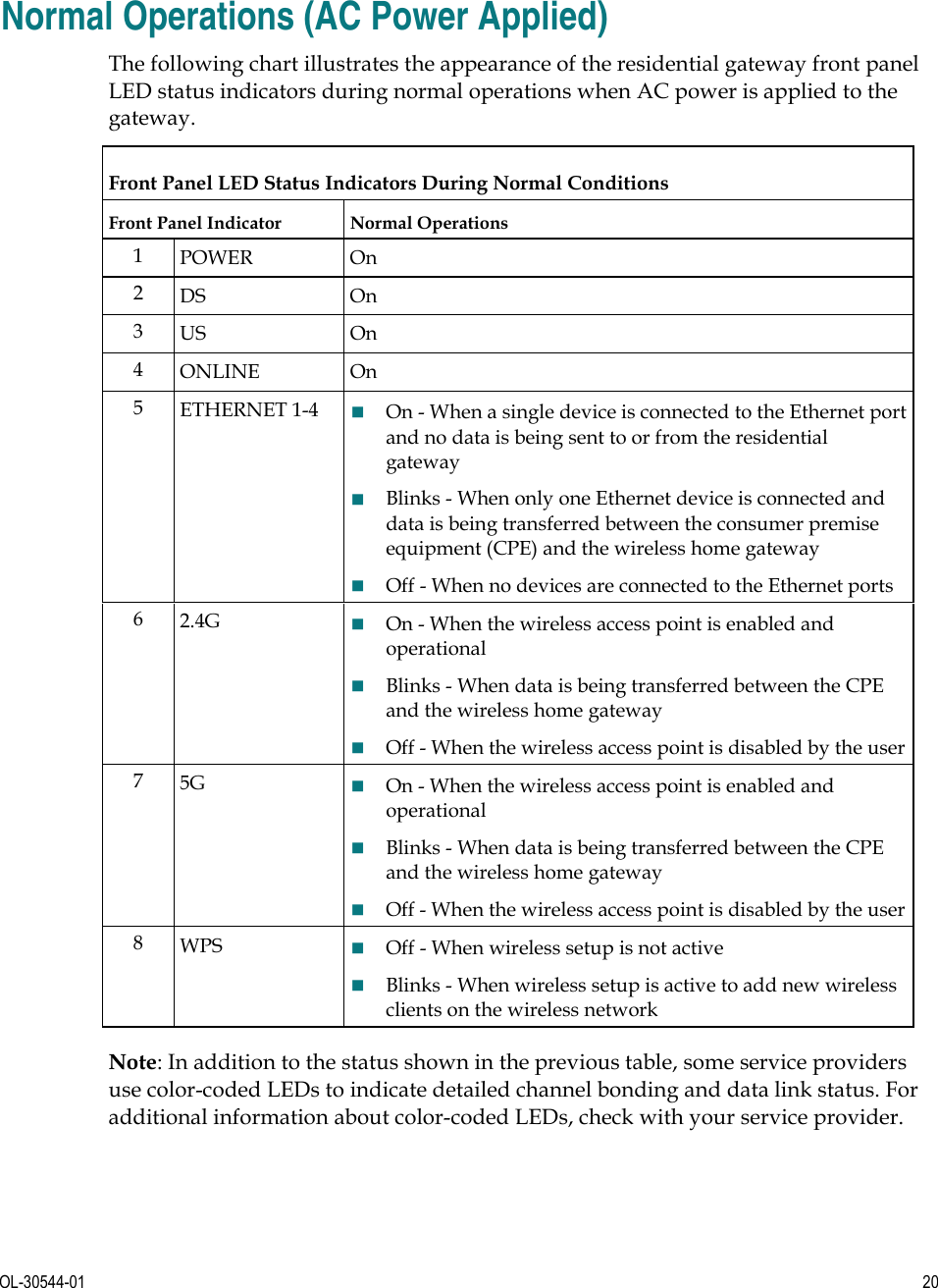
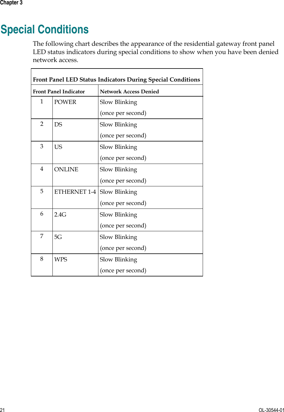
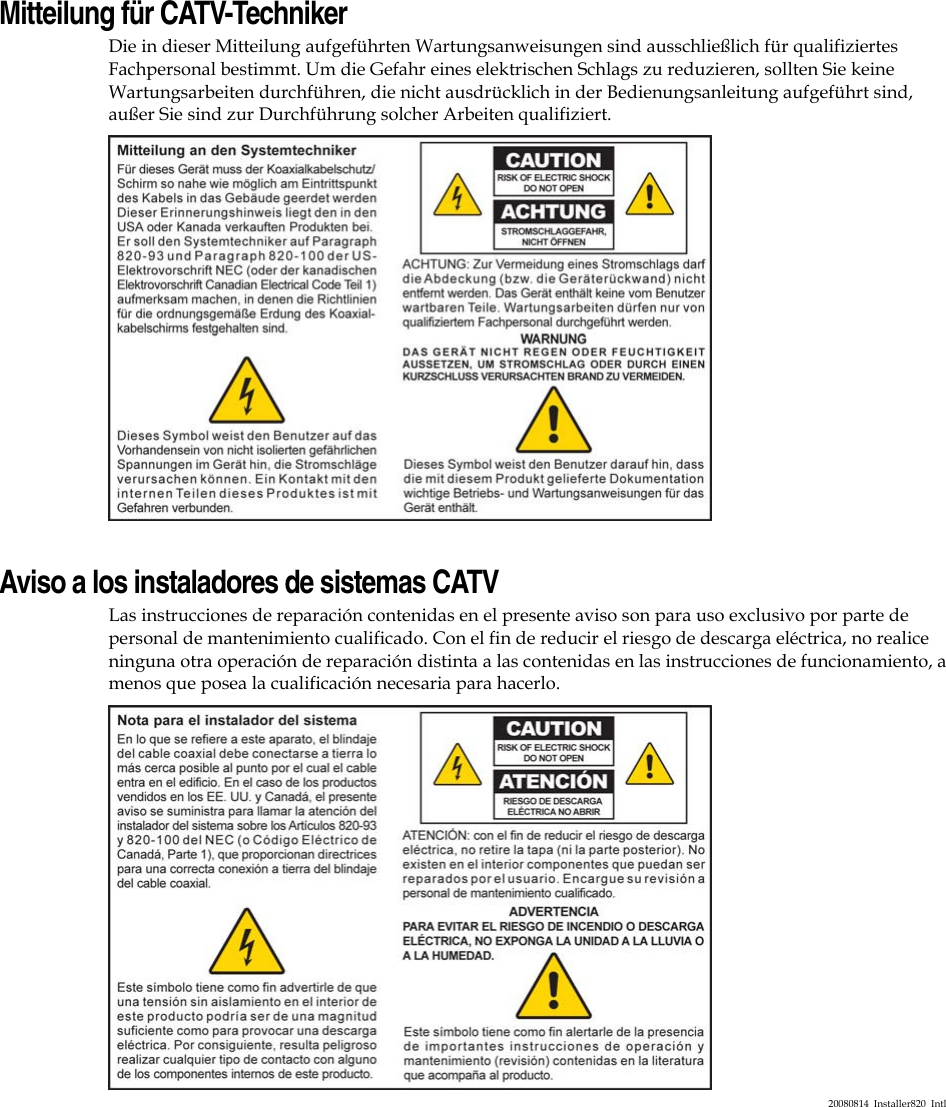
PEGATRON DPC3848 Wireless Residential Gateway User Manual
PEGATRON CORPORATION Wireless Residential Gateway
UserManual.wiki
>
PEGATRON
>
DPC3848 User Manual
User Manual
Navigation menu
Upload a User Manual
Namespaces
Wiki Guide
HTML
PDF
Info
Views
User Manual
Discussion / Help
Navigation


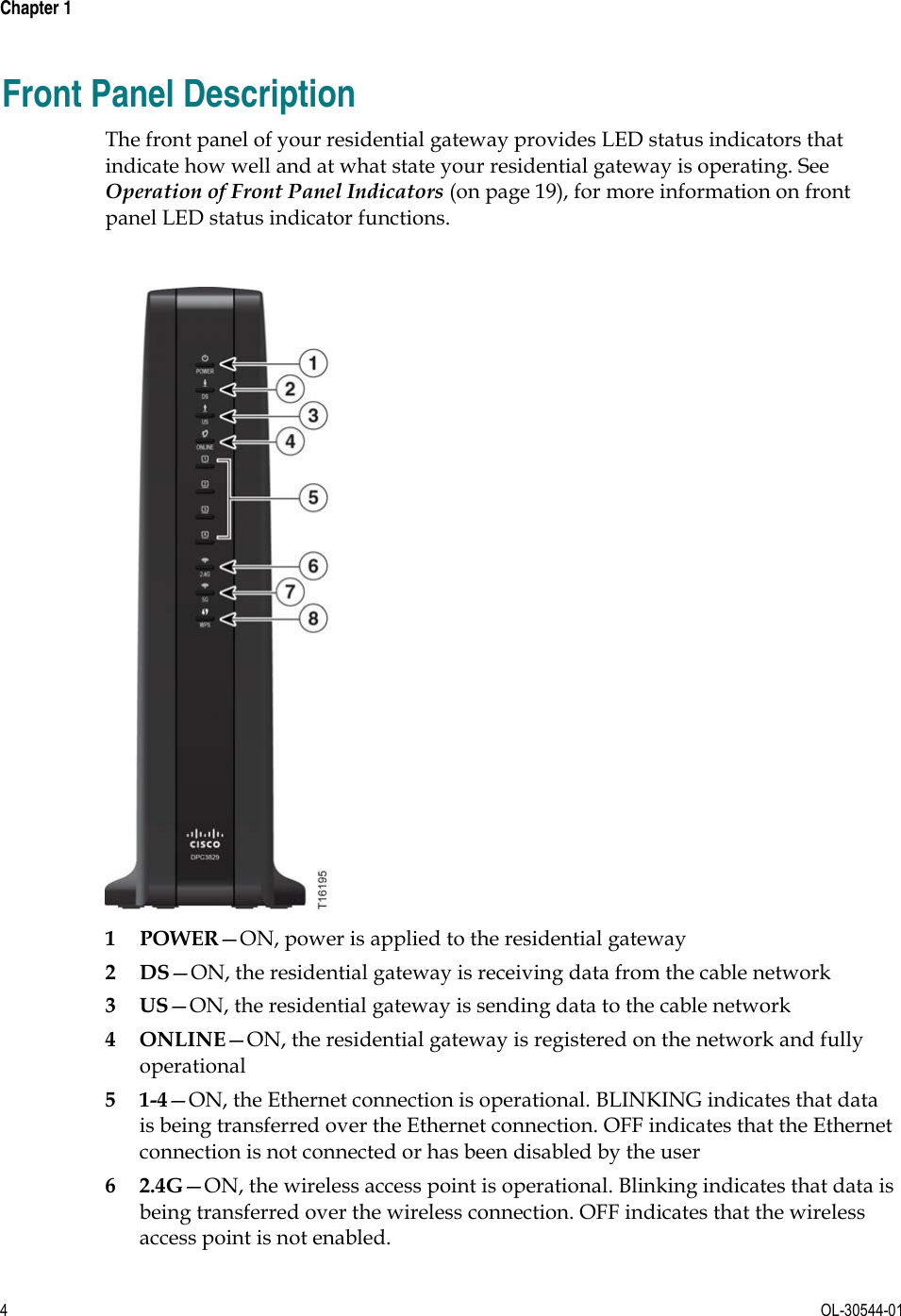
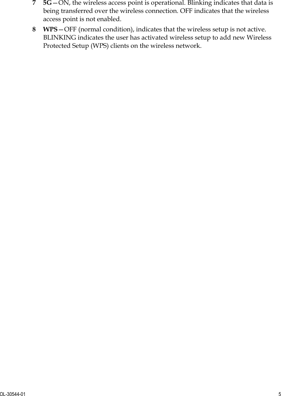
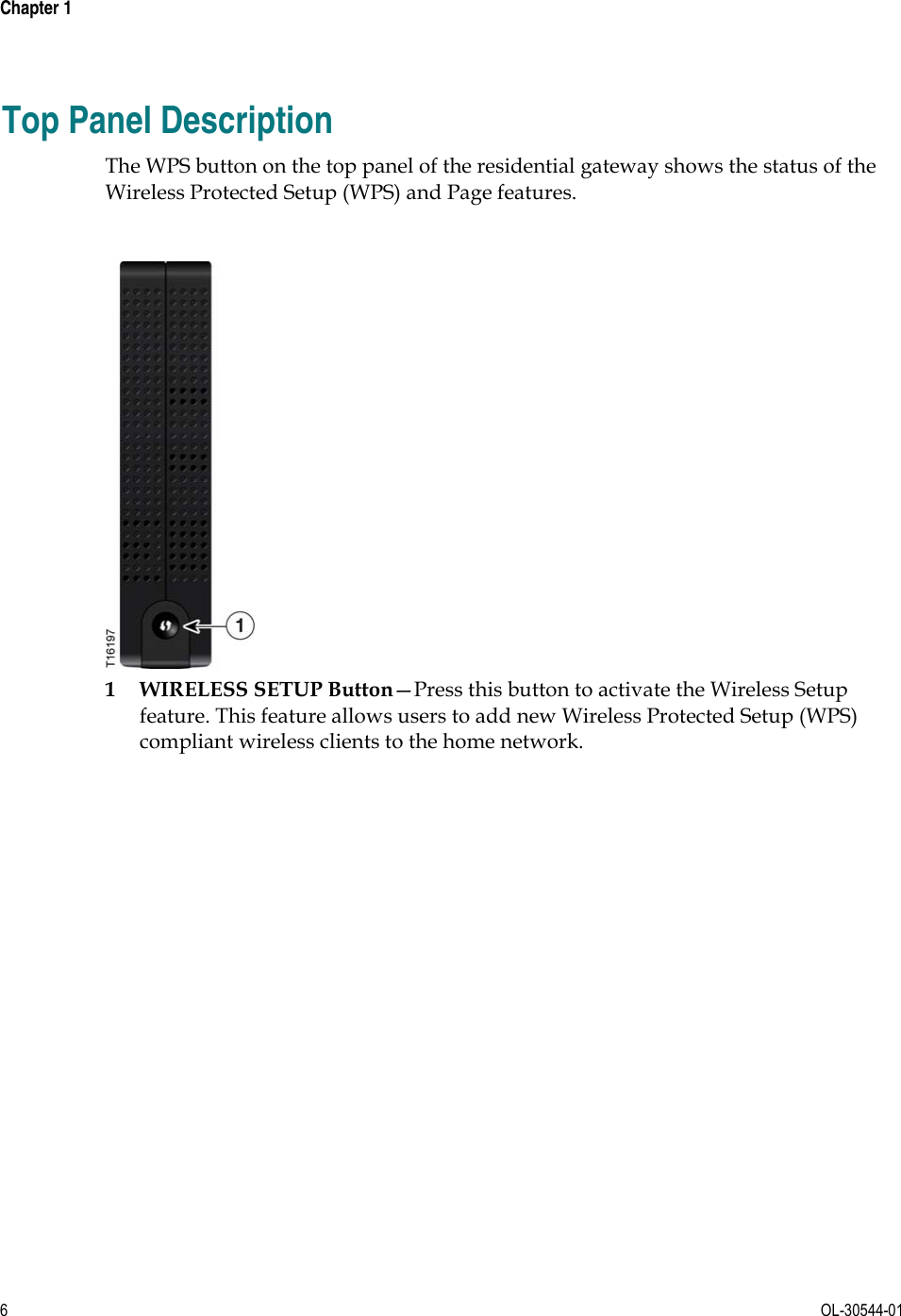
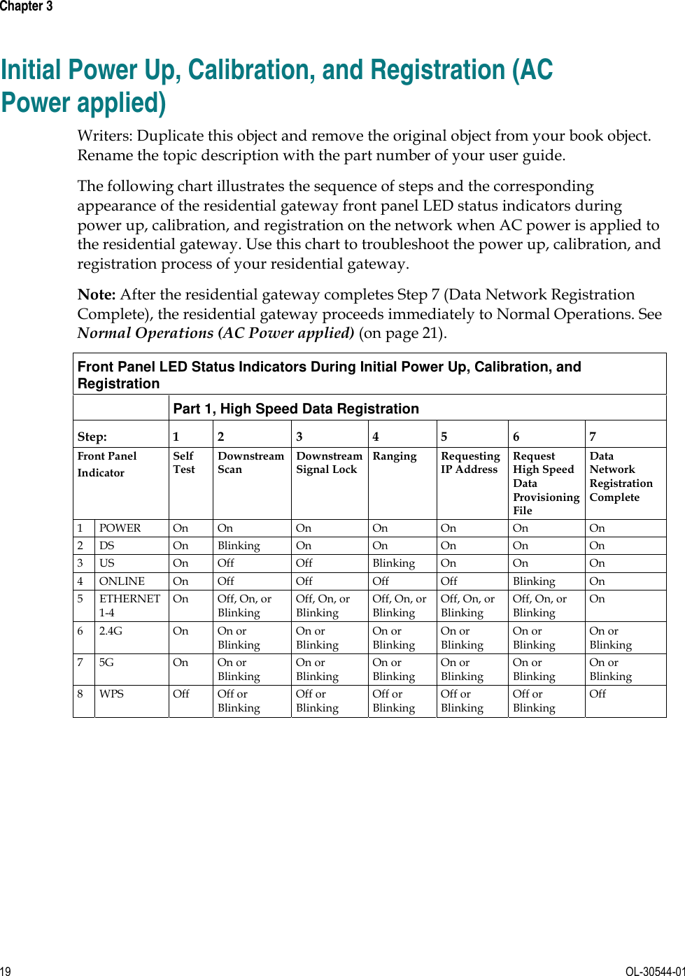
![OL-30544-01 7 Back Panel Description The following illustration identifies the back panel components on the DPC3848 residential gateways. Descriptions for each component follow the illustration. [Note to Team: The following illustration is a placeholder until Srini can get us product images or a datasheet w/product images.] Important: Do not connect your PC to both the Ethernet and USB ports at the same time. Your residential gateway will not function properly if both the Ethernet and USB ports are connected to your PC at the same time. 1 USB (Optional for some models)—Connects to selected devices. For models that support USB, the default is one USB port 2 ETHERNET—Four RJ-45 Ethernet ports connect to the Ethernet port on your PC or your home network 3 WIFI ON/OFF—With both WiFi transmitters on, momentarily pressing this switch once for 1 to 2 seconds will turn off the 2.4G transmitter. Momentarily pressing it a second time turns off the 5G transmitter. Momentarily pressing it a third time turns on both the 2.4G and 5G transmitters.](https://usermanual.wiki/PEGATRON/DPC3848/User-Guide-2135448-Page-23.png)