PEGATRON DPC3848V Wireless Residential Gateway User Manual
PEGATRON CORPORATION Wireless Residential Gateway
PEGATRON >
User Manual

OL-30544-01
Cisco Model DPC3848V
DOCSIS/EuroDOCSIS 3.0 24x8
Wireless Residential Gateway
User Guide
Please Read
Important
Please read this entire guide. If this guide provides installation or operation
instructions, give particular attention to all safety statements included in this guide.
Notices
Trademark Acknowledgments
Cisco and the Cisco logo are trademarks or registered trademarks of Cisco and/or its
affiliates in the U.S. and other countries. To view a list of Cisco trademarks, go to this
URL: www.cisco.com/go/trademarks. DOCSIS is a registered trademark of Cable
Television Laboratories, Inc. EuroDOCSIS, EuroPacketCable, and PacketCable are
trademarks of Cable Television Laboratories, Inc. The Wi-Fi Protected Setup mark is
a mark of the Wi-Fi Alliance. Wi-Fi Protected Setup is a trademark of the Wi-Fi
Alliance.
Other third party trademarks mentioned are the property of their respective owners.
The use of the word partner does not imply a partnership relationship between
Cisco and any other company. (1110R)
Publication Disclaimer
Cisco Systems, Inc. assumes no responsibility for errors or omissions that may
appear in this publication. We reserve the right to change this publication at any
time without notice. This document is not to be construed as conferring by
implication, estoppel, or otherwise any license or right under any copyright or
patent, whether or not the use of any information in this document employs an
invention claimed in any existing or later issued patent.
Disclaimer
The maximum performance for wireless is derived from IEEE Standard 802.11
specifications. Actual performance can vary, including lower wireless network
capacity, data throughput rate, range and coverage. Performance depends on many
factors, conditions and variables, including distance from the access point, volume of
network traffic, building materials and construction, operating system used, mix of
wireless products used, interference and other adverse conditions.
Software and Firmware Use
The software described in this document is protected by copyright law and
furnished to you under a license agreement. You may only use or copy this software
in accordance with the terms of your license agreement.
The firmware in this equipment is protected by copyright law. You may only use the
firmware in the equipment in which it is provided. Any reproduction or distribution
of this firmware, or any portion of it, without our express written consent is
prohibited.
Copyright
© 2013 Cisco Systems, Inc. All rights reserved.
Information in this publication is subject to change without notice. No part of this
publication may be reproduced or transmitted in any form, by photocopy, microfilm,
xerography, or any other means, or incorporated into any information retrieval
system, electronic or mechanical, for any purpose, without the express permission of
Cisco Systems, Inc.
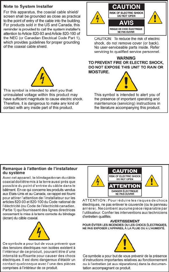
Notice to Installers
The servicing instructions in this notice are for use by qualified service personnel only. To reduce the
risk of electric shock, do not perform any servicing other than that contained in the operating
instructions, unless you are qualified to do so.
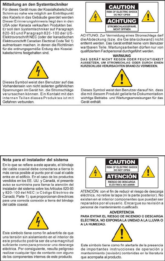
Notice à l’attention des installateurs de réseaux câblés
Les instructions relatives aux interventions d’entretien, fournies dans la présente notice, s’adressent
exclusivement au personnel technique qualifié. Pour réduire les risques de chocs électriques, n’effectuer
aucune intervention autre que celles décrites dans le mode d'emploi et les instructions relatives au
fonctionnement, à moins que vous ne soyez qualifié pour ce faire.
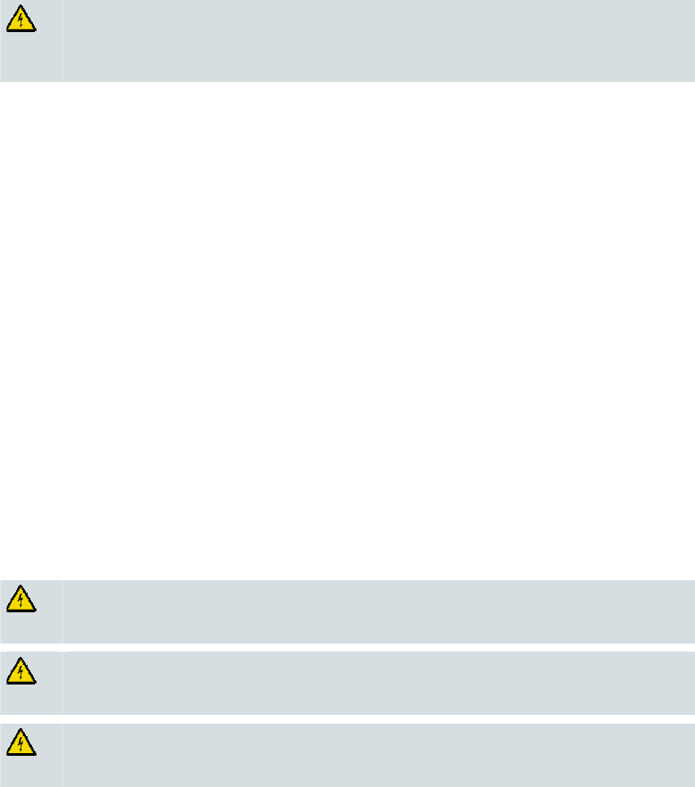
Mitteilung für CATV-Techniker
Die in dieser Mitteilung aufgeführten Wartungsanweisungen sind ausschließlich für qualifiziertes
Fachpersonal bestimmt. Um die Gefahr eines elektrischen Schlags zu reduzieren, sollten Sie keine
Wartungsarbeiten durchführen, die nicht ausdrücklich in der Bedienungsanleitung aufgeführt sind,
außer Sie sind zur Durchführung solcher Arbeiten qualifiziert.
Aviso a los instaladores de sistemas CATV
Las instrucciones de reparación contenidas en el presente aviso son para uso exclusivo por parte de
personal de mantenimiento cualificado. Con el fin de reducir el riesgo de descarga eléctrica, no realice
ninguna otra operación de reparación distinta a las contenidas en las instrucciones de funcionamiento, a
menos que posea la cualificación necesaria para hacerlo.
20080814_Installer820_Intl

United States FCC Compliance
OL-30544-01 vii
IMPORTANT SAFETY INSTRUCTIONS
1) Read these instructions.
2) Keep these instructions.
3) Heed all warnings.
4) Follow all instructions.
5) Do not use this apparatus near water.
6) Clean only with dry cloth.
7) Do not block any ventilation openings. Install in accordance with the
manufacturer's instructions.
8) Do not install near any heat sources such as radiators, heat registers, stoves, or
other apparatus (including amplifiers) that produce heat.
9) Do not defeat the safety purpose of the polarized or grounding-type plug. A
polarized plug has two blades with one wider than the other. A grounding-type
plug has two blades and a third grounding prong. The wide blade or the third
prong are provided for your safety. If the provided plug does not fit into your
outlet, consult an electrician for replacement of the obsolete outlet.
10) Protect the power cord from being walked on or pinched particularly at plugs,
convenience receptacles, and the point where they exit from the apparatus.
11) Only use attachments/accessories specified by the manufacturer.
12) Use only with the cart, stand, tripod, bracket, or table specified by the
manufacturer, or sold with the apparatus. When a cart is used, use caution when
moving the cart/apparatus combination to avoid injury from tip-over.
13) Unplug this apparatus during lightning storms or when unused for long periods of
time.
14) Refer all servicing to qualified service personnel. Servicing is required when the
apparatus has been damaged in any way, such as a power-supply cord or plug is
damaged, liquid has been spilled or objects have fallen into the apparatus, the
apparatus has been exposed to rain or moisture, does not operate normally, or has
been dropped.
Power Source Warning
A label on this product indicates the correct power source for this product. Operate this product only
from an electrical outlet with the voltage and frequency indicated on the product label. If you are
uncertain of the type of power supply to your home or business, consult your service provider or your
local power company.
The AC inlet on the unit must remain accessible and operable at all times.
Ground the Product
WARNING: Avoid electric shock and fire hazard! If this product connects to coaxial
cable wiring, be sure the cable system is grounded (earthed). Grounding provides
some protection against voltage surges and built-up static charges.
United States FCC Compliance
viii OL-30544-01
Protect the Product from Lightning
In addition to disconnecting the AC power from the wall outlet, disconnect the signal inputs.
Verify the Power Source from the On/Off Power Light
When the on/off power light is not illuminated, the apparatus may still be connected to the power
source. The light may go out when the apparatus is turned off, regardless of whether it is still plugged
into an AC power source.
Eliminate AC Power/Mains Overloads
WARNING: Avoid electric shock and fire hazard! Do not overload AC power/mains,
outlets, extension cords, or integral convenience receptacles. For products that require
battery power or other power sources to operate them, refer to the operating
instructions for those products.
Provide Ventilation and Select a Location
Remove all packaging material before applying power to the product.
Do not place this apparatus on a bed, sofa, rug, or similar surface.
Do not place this apparatus on an unstable surface.
Do not install this apparatus in an enclosure, such as a bookcase or rack, unless the installation
provides proper ventilation.
Do not place entertainment devices (such as VCRs or DVDs), lamps, books, vases with liquids, or
other objects on top of this product.
Do not block ventilation openings.
Operating Environment
This product is designed for operation indoors with a temperature range from 32° to 104° F (0° to 40°C).
Each product should have adequate spacing on all sides so that the cooling air vents on the chassis are
not blocked.
Protect from Exposure to Moisture and Foreign Objects
WARNING: Avoid electric shock and fire hazard! Do not expose this product to
dripping or splashing liquids, rain, or moisture. Objects filled with liquids, such as
vases, should not be placed on this apparatus.
WARNING: Avoid electric shock and fire hazard! Unplug this product before cleaning.
Do not use a liquid cleaner or an aerosol cleaner. Do not use a magnetic/static cleaning
device (dust remover) to clean this product.
WARNING: Avoid electric shock and fire hazard! Never push objects through the
openings in this product. Foreign objects can cause electrical shorts that can result in
electric shock or fire.

United States FCC Compliance
OL-30544-01 ix
Service Warnings
WARNING: Avoid electric shock! Do not open the cover of this product. Opening or
removing the cover may expose you to dangerous voltages. If you open the cover, your
warranty will be void. This product contains no user-serviceable parts.
Check Product Safety
Upon completion of any service or repairs to this product, the service technician must perform safety
checks to determine that this product is in proper operating condition.
Protect the Product When Moving It
Always disconnect the power source when moving the apparatus or connecting or disconnecting
cables.

United States FCC Compliance
x OL-30544-01
United States FCC Compliance
This device has been tested and found to comply with the limits for a Class B digital device,
pursuant to part 15 of the FCC Rules. These limits are designed to provide reasonable
protection against such interference in a residential installation. This equipment generates,
uses, and can radiate radio frequency energy. If not installed and used in accordance with the
instructions, it may cause harmful interference to radio communications. However, there is
no guarantee that interference will not occur in a particular installation. If this equipment
does cause harmful interference to radio or television reception, which can be determined by
turning the equipment OFF and ON, the user is encouraged to try to correct the interference
by one or more of the following measures:
Reorient or relocate the receiving antenna.
Increase the separation between the equipment and receiver.
Connect the equipment into an outlet on a circuit different from that to which the
receiver is connected.
Consult the service provider or an experienced radio/television technician for help.
Any changes or modifications not expressly approved by Cisco Systems, Inc., could void the
user's authority to operate the equipment.
The information shown in the FCC Declaration of Conformity paragraph below is a
requirement of the FCC and is intended to supply you with information regarding the FCC
approval of this device. The phone numbers listed are for FCC-related questions only and not
intended for questions regarding the connection or operation for this device. Please contact your
service provider for any questions you may have regarding the operation or installation of this device.
Declaration of Conformity
This device complies with Part 15 of FCC
Rules. Operation is subject to the following
two conditions: 1) the device may not cause
harmful interference, and 2) the device must
accept any interference received, including
interference that may cause undesired
operation.
DOCSIS Wireless Residential Gateway
Model(s): DPC3848V
Manufactured by:
Cisco Systems, Inc.
5030 Sugarloaf Parkway
Lawrenceville, Georgia 30044 USA
United States FCC Compliance
OL-30544-01 xi
RF Exposure Statements
This device and its antennas(s) must not be co-located or operating in conjunction with any
other antenna or transmitter except in accordance with IC multi-transmitter product
procedures. For product available in the USA/Canada market, only channel 1~11 can be
operated. Selection of other channels is not possible.
Cet appareil et son antenne (s) ne doit pas être co-localisés ou fonctionnement en association
avec une autre antenne ou transmetteur. Pour les produits disponibles aux États-Unis /
Canada du marché, seul le canal 1 à 11 peuvent être exploités. Sélection d'autres canaux n'est
pas possible.
US
This device and it's antennas(s) must not be co-located or operating in conjunction with any
other antenna or transmitter except in accordance with FCC multi-transmitter product
procedures.
FCC Radiation Exposure Statement:
This equipment complies with FCC radiation exposure limits set forth for an uncontrolled
environment. This equipment should be installed and operated with minimum distance 20cm
between the radiator & your body.

United States FCC Compliance
OL-30544-01 xiii
Canada Compliance
This device complies with Industry Canada
license-exempt RSS standard(s). Operation is
subject to the following two conditions: 1) this
device may not cause interference, and 2) this
device must accept any interference received,
including interference that may cause
undesired operation of the device.
Le présent appareil est conforme aux CNR
d'Industrie Canada applicables aux appareils
radio exempts de licence. L'exploitation est
autorisée aux deux conditions suivantes : (1)
l'appareil ne doit pas produire de brouillage, et
(2) l'utilisateur de l'appareil doit accepter tout
brouillage radioélectrique subi, même si le
brouillage est susceptible d'en compromettre le
fonctionnement.
DOCSIS Wireless Residential Gateway
Model(s): DPC3848V
Manufactured by:
Cisco Systems, Inc.
5030 Sugarloaf Parkway
Lawrenceville, Georgia 30044 USA
IC Radiation Exposure Statement
This equipment complies with IC RSS-102 radiation exposure limits set forth for an
uncontrolled environment. This equipment should be installed and operated with minimum
distance 20cm between the radiator & your body.
Cet équipement est conforme aux limites d'exposition aux rayonnements IC établies pour un
environnement non contrôlé. Cet équipement doit être installé et utilisé avec un minimum de
20 cm de distance entre la source de rayonnement et votre corps.
CE Compliance
OL-30544-01 xv
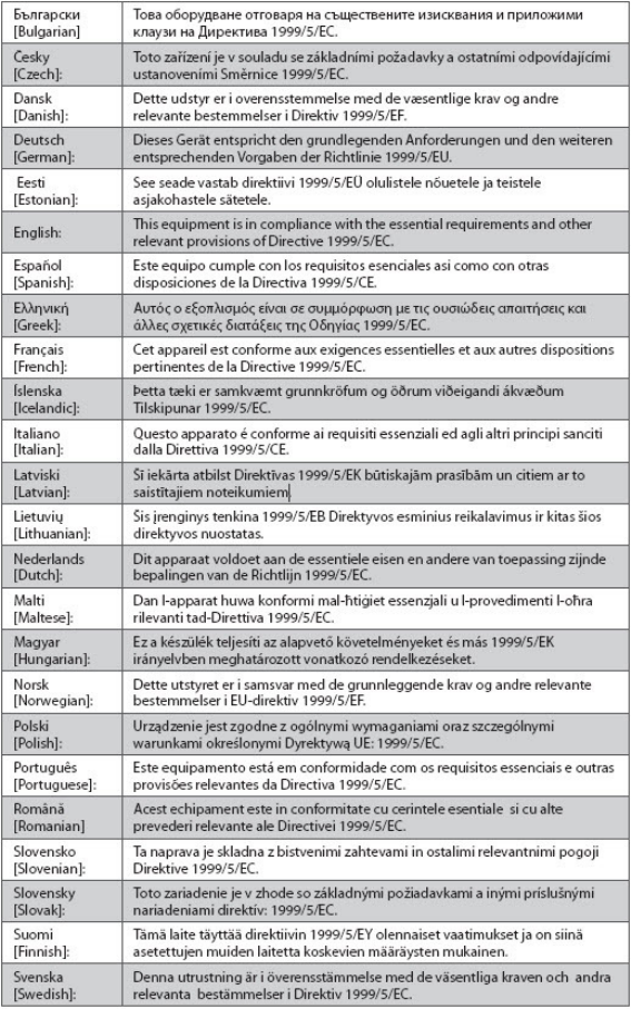
CE Compliance
Declaration of Conformity with Regard to the EU Directive 1999/5/EC
(R&TTE Directive)
This declaration is only valid for configurations (combinations of software, firmware and
hardware) supported or provided by Cisco Systems for use within the EU. The use of
software or firmware not supported or provided by Cisco Systems may result in the
equipment no longer being compliant with the regulatory requirements.

CE Compliance
xvi OL-30544-01
Note: The full declaration of conformity for this product can be found at
http://www.cisco.com/web/consumer/support/compliance_info.html.
The following standards were applied during the assessment of the product against the
requirements of the Directive 1999/5/EC:
Radio: EN 300 328
EMC: EN 301 489-1 and EN 301 489-17
Safety: EN 60950 and EN 50385
The CE mark and class-2 identifier are affixed to the product and its packaging. This product
conforms to the following European directives:
-1999/5/EC
National Restrictions
This product is for indoor use only.
USA/Canada
This system has been evaluated for RS-210. When operating this system, adhere to the
following requirements:
When operating in the band 5150-5250 MHz, the device is only for indoor use to reduce
the potential for harmful interference to co-channel mobile satellite systems.
CE Compliance
OL-30544-01 xvii
Ce système a été évalué pour les normes radioélectriques RS-210. Lorsque vous exploitez ce
système, respectez les exigences listées ci-dessous.
Quand l'appareil est exploité dans la bande 5150-5250 MHz, il peut uniquement être
utilisé à l'intérieur pour réduire le risque de brouillage préjudiciable qui pourrait affecter
les systèmes satellites portables sur la même voie.
France
For 2.4 GHz, the output power is restricted to 10 mW EIRP when the product is used
outdoors in the band 2454 - 2483.5 MHz. There are no restrictions when used in other parts of
the 2.4 GHz band. Check http://www.arcep.fr/ for more details.
Pour la bande 2,4 GHz, la puissance est limitée à 10 mW en p.i.r.e. pour les équipements
utilisés en extérieur dans la bande 2454 - 2483,5 MHz. Il n'y a pas de restrictions pour des
utilisations dans d'autres parties de la bande 2,4 GHz. Consultez http://www.arcep.fr/ pour
de plus amples détails.
Italy
This product meets the National Radio Interface and the requirements specified in the
National Frequency Allocation Table for Italy. Unless this wireless LAN product is operating
within the boundaries of the owner's property, its use requires a “general authorization.”
Please check http://www.comunicazioni.it/it/ for more details.
Questo prodotto è conforme alla specifiche di Interfaccia Radio Nazionali e rispetta il Piano
Nazionale di ripartizione delle frequenze in Italia. Se non viene installato all 'interno del
proprio fondo, l'utilizzo di prodotti Wireless LAN richiede una “Autorizzazione Generale”.
Consultare http://www.comunicazioni.it/it/ per maggiori dettagli.
Latvia
The outdoor usage of the 2.4 GHz band requires an authorization from the Electronic
Communications Office. Please check http://www.esd.lv for more details.
2,4 GHz frekvenču joslas izmantošanai ārpus telpām nepieciešama atļauja no Elektronisko
sakaru direkcijas. Vairāk informācijas: http://www.esd.lv.
Note: The regulatory limits for maximum output power are specified in EIRP. The EIRP level
of a device can be calculated by adding the gain of the antenna used (specified in dBi) to the
output power available at the connector (specified in dBm).
Antennas
Use only the antenna supplied with the product.
20110311_CE_Gateway
About This Guide
OL-30544-01 xix
About This Guide
Introduction
Welcome. This guide provides instructions and recommendations for placing,
installing, configuring, operating, maintaining, and troubleshooting the DPC3848V
DOCSIS Wireless Residential Gateways.
Purpose
This guide covers the following product models:
DPC3848V DOCSIS Wireless Residential Gateway
All features described in this guide are standard to these models of residential
gateways unless otherwise noted. For the purpose of this guide, whenever a feature
or option applies to only a specific model, the model number is specified. If a model
number is not specified, then the feature or option applies to both of the models.
Audience
This guide is written for the home subscriber.
Document Version
This is the first formal release of this document.

OL-30544-01 1
Introduction
This chapter provides an overview of residential gateway features,
indicators, and connectors to help you become familiar with the
residential gateway and the benefits it offers. This chapter also lists the
accessories and equipment that are provided with the residential
gateway so you can verify that you received all of these items.
1 Chapter 1
Introducing the DOCSIS
Wireless Residential Gateway
In This Chapter
Introduction............................................................................................. 2
What's In the Carton?............................................................................. 3
Front Panel Description ......................................................................... 4
Bottom Panel Description...................................................................... 6
Top Panel Description............................................................................ 6
Back Panel Description .......................................................................... 7
Chapter 1
2 OL-30544-01
Introduction
Your new Cisco® Model DPC3848V DOCSIS® 3.0 Wireless Residential Gateway is a
cable modem that meets industry standards for high-speed data connectivity. The
DPC3848V residential gateway delivers data and wired (Ethernet) or wireless gateway
capabilities to connect a variety of devices in the home or small office and support
high-speed data access and cost-effective voice services, all in one device.
This guide provides procedures and recommendations for placing, installing,
configuring, operating, and troubleshooting your DPC3848V residential gateway for
high-speed Internet for your home or office. Refer to the appropriate section in this
guide for the specific information you need for your situation. Contact your service
provider for more information about subscribing to these services.
Your new residential gateway offers the following outstanding benefits and features:
Compliant with DOCSIS and EuroDOCSIS 3.0, 2.0, and 1.x standards along with
PacketCable™ and EuroPacketCable™ specifications to deliver high-end
performance and reliability
High performance broadband Internet connectivity to energize your online
experience
Four 1000/100/10BASE-T Ethernet ports to provide wired connectivity
802.11n/ac Wireless Access Point
User configurable Parental Control blocks access to undesirable Internet sites
Advanced firewall technology deters hackers and protects the home network
from unauthorized access
Attractive compact design and versatile orientation to stand vertically on a desk
or shelf, or mount easily to a wall.
Color-coded interface ports and corresponding cables simplify installation and
setup
DOCSIS-compliant LED labeling and behavior provides a user and technician
friendly method to check operational status and act as a troubleshooting tool
Allows automatic software upgrades by your service provider
OL-30544-01 3
What's In the Carton?
When you receive your residential gateway, you should check the equipment and
accessories to verify that each item is in the carton and that each item is undamaged.
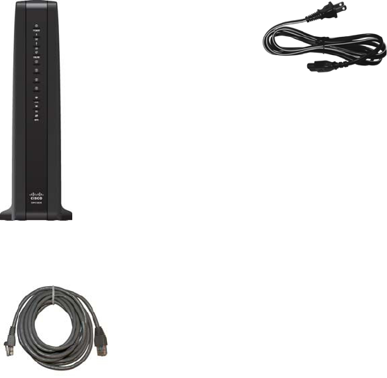
The carton contains the following items:
One DPC3848V DOCSIS
Wireless Residential Gateway
One AC power cord (Image may vary
from product. Item varies based on the
region where the item is used.)
One Ethernet cable (May not be
provided with all products.)
If any of these items are missing or damaged, please contact your service provider
for assistance.
Notes:
You need an optional cable signal splitter and additional standard RF coaxial
cables if you want to connect a VCR, a Digital Home Communications Terminal
(DHCT) or a set-top converter, or a TV to the same cable connection as your
residential gateway.
If your product supports telephone service, cables and other equipment needed
for telephone service must be purchased separately. Contact your service
provider to inquire about the equipment and cables you need for telephone
service.
Chapter 1
4 OL-30544-01
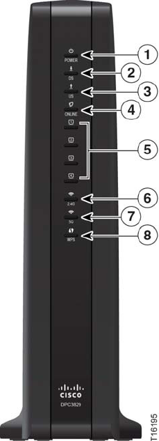
Front Panel Description
The front panel of your residential gateway provides LED status indicators that
indicate how well and at what state your residential gateway is operating. See
Operation of Front Panel Indicators (on page 19), for more information on front
panel LED status indicator functions.
1 POWER—ON, power is applied to the residential gateway
2 DS—ON, the residential gateway is receiving data from the cable network
3 US—ON, the residential gateway is sending data to the cable network
4 ONLINE—ON, the residential gateway is registered on the network and fully
operational
5 1-4—ON, the Ethernet connection is operational. BLINKING indicates that data
is being transferred over the Ethernet connection. OFF indicates that the Ethernet
connection is not connected or has been disabled by the user
6 2.4G—ON, the wireless access point is operational. Blinking indicates that data is
being transferred over the wireless connection. OFF indicates that the wireless
access point is not enabled.
OL-30544-01 5
7 5G—ON, the wireless access point is operational. Blinking indicates that data is
being transferred over the wireless connection. OFF indicates that the wireless
access point is not enabled.
8 WPS—OFF (normal condition), indicates that the wireless setup is not active.
BLINKING indicates the user has activated wireless setup to add new Wireless
Protected Setup (WPS) clients on the wireless network.
Chapter 1
6 OL-30544-01
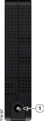
Top Panel Description
The WPS button on the top panel of the residential gateway shows the status of the
Wireless Protected Setup (WPS) and Page features.
1 WIRELESS SETUP Button—Press this button to activate the Wireless Setup
feature. This feature allows users to add new Wireless Protected Setup (WPS)
compliant wireless clients to the home network.
OL-30544-01 7
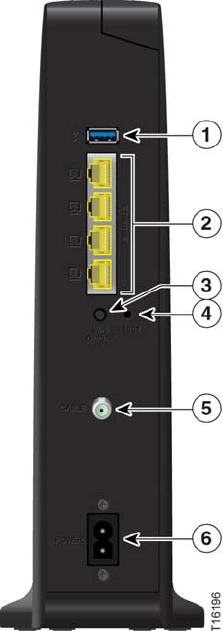
Back Panel Description
The following illustration identifies the back panel components on the DPC3848V
residential gateways. Descriptions for each component follow the illustration.
[Note to Team: The following illustration is a placeholder until Srini can get us
product images or a datasheet w/product images.]
Important: Do not connect your PC to both the Ethernet and USB ports at the same
time. Your residential gateway will not function properly if both the Ethernet and
USB ports are connected to your PC at the same time.
1 USB (Optional for some models)—Connects to selected devices. For models that
support USB, the default is one USB port
2 ETHERNET—Four RJ-45 Ethernet ports connect to the Ethernet port on your PC
or your home network
3 WIFI ON/OFF—With both WiFi transmitters on, momentarily pressing this
switch once for 1 to 2 seconds will turn off the 2.4G transmitter. Momentarily
pressing it a second time turns off the 5G transmitter. Momentarily pressing it a
third time turns on both the 2.4G and 5G transmitters.

Chapter 1
8 OL-30544-01
4 RESET—A momentary pressing (1-2 seconds) of this button performs a software
reset the device. Pressing and holding the button for more than ten seconds first
causes a reset-to-factory-default of all settings and then performs a software reset
of the device
CAUTION:
The RESET button is for maintenance purposes only. Do not use unless
instructed to do so by your service provider. Doing so may cause you to lose
any settings you have selected.
5 CABLE—F-connector connects to an active cable signal from your service
provider
6 POWER—Connects the residential gateway to the AC wall outlet

OL-30544-01 9
Introduction
This chapter describes how to properly install the residential gateway
and to connect the residential gateway to a computer and other
devices.
2 Chapter 2
Installing the DOCSIS Wireless
Residential Gateway
In This Chapter
Installation Preparations...................................................................... 10
Install the Wireless Residential Gateway .......................................... 15
Chapter 2
10 OL-30544-01
Installation Preparations
Before installing the residential gateway, make sure that your system meets or
exceeds the requirements listed in this section. Also, make sure that you have
prepared your home and home devices as described in this section.
What Are the System Requirements for Internet Service?
To ensure that your residential gateway operates efficiently for high-speed Internet
service, you must have an Internet-capable PC, Mac, or Internet appliance equipped
with an Ethernet port or WiFi capability.
Note: You will also need an active cable input line and an Internet connection.
What Types of Service Accounts Do I Need?
Depending upon the features your service provider offers, you may need to establish
one or both of the following accounts:
A high-speed Internet access account, if your residential gateway supports an
Internet connection
An account for telephone service, if your residential gateway supports digital
telephone service
Refer to one of the following topics to learn more about the types of service accounts
that you may need to establish.
High-Speed Internet Access Account
If you do not have a high-speed Internet access account, your service provider will
set up your account and become your Internet Service Provider (ISP). Internet access
enables you to send and receive e-mail, access the World Wide Web, and receive
other Internet services.
You will need to give your service provider information about the residential
gateway in order to use the high-speed Internet feature that this product offers.
Refer to Information Your Service Provider Needs (on page 11) to learn how to locate
the information your service provider needs to establish a high-speed Internet access
account for the residential gateway
If you have an existing high-speed Internet access account, you will need to give
your service provider the serial number and MAC address of the residential gateway
in order to use the high-speed Internet feature that this product offers. Refer to
Information Your Service Provider Needs (on page 11) to learn how to locate this
information.
OL-30544-01 11
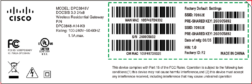
Information Your Service Provider Needs
You will need to give your service provider the following information, which is
printed on the bar code label attached to the device:
The Serial Number (S/N) of the residential gateway. The serial number
consists of a series of nine digits.
The Media Access Control (CM MAC) address of the residential gateway. The
CM MAC address consists of a series of 12 alphanumeric characters.
The Media Access Control (MAC) address of the residential gateway media
terminal adapter (MTA MAC). The MTA MAC address consists of a series of 12
alphanumeric characters.
The following illustration shows a typical bar coded label; the image may vary from
the label on the actual product.
Write down these numbers in the spaces provided:
Serial Number _______________________
CM MAC Address ________________________
MTA MAC Address ________________________
I Already Have a High-Speed Internet Access Account
Where Is the Best Location for My Wireless Residential Gateway?
The ideal location for your residential gateway is where it has access to outlets and
other devices. Think about the layout of your home or office, and consult with your
service provider to select the best location for your residential gateway. Read this
user guide thoroughly before you decide where to place your residential gateway.
Chapter 2
12 OL-30544-01
Choose a location close to your computer if you will also use the residential
gateway for high-speed Internet service.
Choose a location that is near an existing RF coaxial connection to eliminate the
need for an additional RF coaxial outlet.
Choose a location that is relatively protected from accidental disturbance or
harm, such as a closet, basement, or other protected area.
Choose a location so that there is plenty of room to guide the cables away from
the residential gateway without straining or crimping them.
Choose a location that allows adequate ventilation around the residential
gateway.
How Do I Mount the Wireless Residential Gateway on a Wall? (Optional)
Your residential gateway may include mounting holes so that, if you wish, you can
mount the residential gateway to a wall. This section describes how to mount the
residential gateway to a wall, and includes a list of equipment you will need along
with suggestions for choosing an appropriate place to mount the residential
gateway.
Select an Appropriate Place to Mount the Wireless Residential Gateway
You may mount the residential gateway to a wall that is made of cement, wood, or
drywall. When choosing an appropriate mounting place, refer to the following
recommendations:
Ensure that the mounting location is free of obstructions on all sides, and the
cables should be able to easily reach the residential gateway without strain.
Leave sufficient clearance between the bottom of the residential gateway and any
flooring or shelving underneath to allow access to cabling.
Allow enough slack in all cables so that the residential gateway can be removed
for any required maintenance without disconnecting the cables.
Choose a location that allows adequate ventilation around the residential
gateway.
OL-30544-01 13
Equipment Needed
Verify that you have the following items that you will need to mount the residential
gateway:
Two wall anchors for #8 x 1-inch screws
Two #8 x 1-inch pan head sheet metal screws
Drill with a 3/16-in. wood or masonry bit, as appropriate for the wall
composition
A copy of the wall-mounting illustrations shown on the following pages
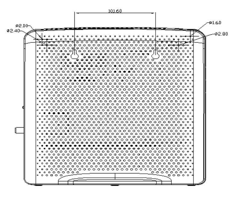
Location and Dimensions of the Wall-Mounting Slots
The following illustration shows the location and dimensions of the wall-mounting
slots on the side of the residential gateway. Use this illustration as a guide for
mounting the residential gateway to the wall.
Note: Image not to scale.
Chapter 2
14 OL-30544-01
Mounting the Wireless Residential Gateway on a Wall
1 Using a drill with a 3/16-inch bit, drill two holes at the same height and 4 inches
apart.
Note: The preceding graphic illustrates the location of the mounting holes on the
back of the residential gateway.
2 Are you mounting the residential gateway into a drywall or concrete surface
where a wooden stud is available?
If yes, go to step 3.
If no, drive the anchor bolts into the wall, and install the mounting screws
into the anchor bolts; leave a gap of about 1/2-inch between the screw head
and the wall. Then, go to step 4.
3 Install the mounting screws into the wall; leave a gap of about 1/2-inch between
the screw head and the wall. Then, go to step 4.
4 Verify that no cables or wires are connected to the residential gateway.
5 Lift the residential gateway into position. Slip the large end of both mounting
slots (located in the side of the residential gateway) over the mounting screws,
and then slide the residential gateway down until the narrow end of the keyhole
slot contacts the screw shaft.
Important: Verify that the mounting screws securely support the residential
gateway before you release the unit.
OL-30544-01 15
Install the Wireless Residential Gateway
This section describes how to connect your residential gateway to support the
services that the residential gateway offers.
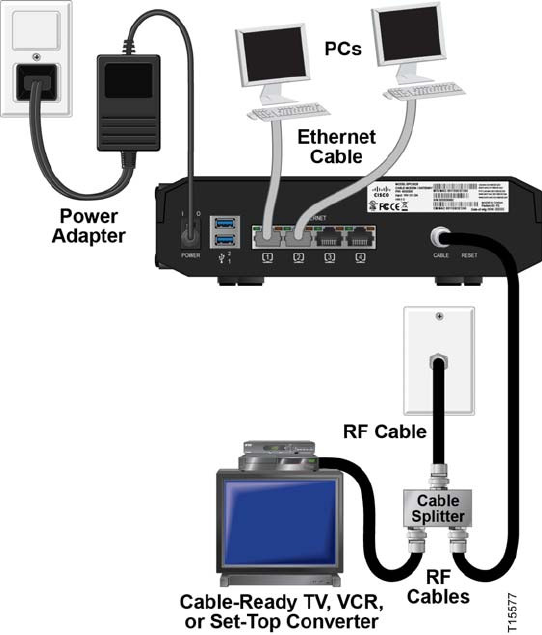
Connect Devices to the Wireless Residential Gateway
The following illustration shows all of the possible connections that can be made to
your residential gateway for various services. Although your model may not
support all of the services pictured, you can determine which services your model
supports by referring to the Benefits and Features list in Introduction (on page 2).
Notes:
Professional installation may be available. Contact your local service provider for
further assistance.
Device image varies according to model.

Chapter 2
16 OL-30544-01
Connect the Wireless Residential Gateway
The following installation procedure ensures proper setup and configuration for the
residential gateway.
1 Choose an appropriate and safe location to install the residential gateway (close
to a power source, an active cable connection, your PC-if using high-speed
Internet, and your telephone lines-if using VoIP). For assistance, refer to Where Is
the Best Location for My Wireless Residential Gateway? (on page 11).
WARNING:
To avoid personal injury, follow the installation instructions in the exact
order shown.
Wiring and connections must be properly insulated to prevent electrical
shock.
Disconnect power from the residential gateway before attempting to
connect to any device.
2 Power off your PC and other networking device; then, unplug them from the
power source.
3 Connect the active RF coaxial cable from your service provider to the coax
connector labeled CABLE on the back of the residential gateway.
Note: To connect a TV, DHCT, set-top, or VCR from the same cable connection,
you will need to install a cable signal splitter (not included). Always check with
your service provider before using a splitter as a splitter may degrade the signal.
4 Connect your PC to the residential gateway using one of the following methods:
Ethernet Connection. Connect one end of an Ethernet cable to the Ethernet
port on your PC, and connect the other end to the Ethernet port on the back
of the residential gateway.
Wireless Connection. Make sure that your wireless device is powered up.
You will need to associate your wireless device with the residential gateway
once the residential gateway is operational. Follow the directions provided
with your wireless device for associating with a wireless access point. Make
sure that either the 2.4G or the 5G indicator is ON.
5 Locate the AC power cord provided with your residential gateway. Connect the
barrel connector end of the power cord into the power input on the back of the
residential gateway. Then, plug the other end of the power cord into an AC
outlet.
The residential gateway will perform an automatic search to locate and sign on
to the broadband data network. This process may take up to 2-5 minutes. The
residential gateway will be ready for use when the Power, US/DS, and Online
LEDs on the front panel of the residential gateway stop blinking and remain on
continuously.
6 Plug in and power on your PC and other home network devices. If one or more
of these devices uses wireless networking, the 2.4G or 5G LED on the residential
gateway should be on or blinking.
OL-30544-01 17
7 At this point, the installation is complete, and you can begin surfing the Internet.
Note: If your PC does not have Internet access, refer to How Do I Configure
TCP/IP Protocol? (on page 24) for information on how to configure your PC for
TCP/IP. For Internet devices other than PCs, refer to the DHCP or IP Address
configuration section of the User Guide or Operations Manual for those devices.

OL-30544-01 18
Introduction
This section describes the behavior of the front panel indicators when
the residential gateway is first powered up, during normal operations,
and in special conditions.
3 Chapter 3
Operation of Front Panel
Indicators
In This Chapter
Initial Power Up, Calibration, and Registration (AC Power
applied) .................................................................................................. 20
Normal Operations (AC Power Applied) ......................................... 21
Special Conditions ................................................................................ 22

Chapter 3
19 OL-30544-01
Initial Power Up, Calibration, and Registration (AC
Power applied)
Writers: Duplicate this object and remove the original object from your book object.
Rename the topic description with the part number of your user guide.
The following chart illustrates the sequence of steps and the corresponding
appearance of the residential gateway front panel LED status indicators during
power up, calibration, and registration on the network when AC power is applied to
the residential gateway. Use this chart to troubleshoot the power up, calibration, and
registration process of your residential gateway.
Note: After the residential gateway completes Step 7 (Data Network Registration
Complete), the residential gateway proceeds immediately to Normal Operations. See
Normal Operations (AC Power applied) (on page 21).
Front Panel LED Status Indicators During Initial Power Up, Calibration, and
Registration
Part 1, High Speed Data Registration
Step: 1 2 3 4 5 6 7
Front Panel
Indicator
Self
Test
Downstream
Scan
Downstream
Signal Lock
Ranging Requesting
IP Address
Request
High Speed
Data
Provisioning
File
Data
Network
Registration
Complete
1 POWER On On On On On On On
2 DS On Blinking On On On On On
3 US On Off Off Blinking On On On
4 ONLINE On Off Off Off Off Blinking On
5 ETHERNET
1-4
On Off, On, or
Blinking
Off, On, or
Blinking
Off, On, or
Blinking
Off, On, or
Blinking
Off, On, or
Blinking
On
6 2.4G On On or
Blinking
On or
Blinking
On or
Blinking
On or
Blinking
On or
Blinking
On or
Blinking
7 5G On On or
Blinking
On or
Blinking
On or
Blinking
On or
Blinking
On or
Blinking
On or
Blinking
8 WPS Off Off or
Blinking
Off or
Blinking
Off or
Blinking
Off or
Blinking
Off or
Blinking
Off

OL-30544-01 20
Normal Operations (AC Power Applied)
The following chart illustrates the appearance of the residential gateway front panel
LED status indicators during normal operations when AC power is applied to the
gateway.
Front Panel LED Status Indicators During Normal Conditions
Front Panel Indicator Normal Operations
1 POWER On
2 DS On
3 US On
4 ONLINE On
5 ETHERNET 1-4
On - When a single device is connected to the Ethernet port
and no data is being sent to or from the residential
gateway
Blinks - When only one Ethernet device is connected and
data is being transferred between the consumer premise
equipment (CPE) and the wireless home gateway
Off - When no devices are connected to the Ethernet ports
6 2.4G
On - When the wireless access point is enabled and
operational
Blinks - When data is being transferred between the CPE
and the wireless home gateway
Off - When the wireless access point is disabled by the user
7 5G
On - When the wireless access point is enabled and
operational
Blinks - When data is being transferred between the CPE
and the wireless home gateway
Off - When the wireless access point is disabled by the user
8 WPS
Off - When wireless setup is not active
Blinks - When wireless setup is active to add new wireless
clients on the wireless network
Note: In addition to the status shown in the previous table, some service providers
use color-coded LEDs to indicate detailed channel bonding and data link status. For
additional information about color-coded LEDs, check with your service provider.

Chapter 3
21 OL-30544-01
Special Conditions
The following chart describes the appearance of the residential gateway front panel
LED status indicators during special conditions to show when you have been denied
network access.
Front Panel LED Status Indicators During Special Conditions
Front Panel Indicator Network Access Denied
1 POWER Slow Blinking
(once per second)
2 DS Slow Blinking
(once per second)
3 US Slow Blinking
(once per second)
4 ONLINE Slow Blinking
(once per second)
5 ETHERNET 1-4 Slow Blinking
(once per second)
6 2.4G Slow Blinking
(once per second)
7 5G Slow Blinking
(once per second)
8 WPS Slow Blinking
(once per second)

OL-30544-01 22
Introduction
This chapter describes the most common issues that may occur after
the residential gateway is installed and provides possible solutions
and tips for improved performance of the residential gateway.
4 Chapter 4
Troubleshooting the DOCSIS
Wireless Residential Gateway
In This Chapter
Frequently Asked Questions............................................................... 24
Common Troubleshooting Issues....................................................... 29
Tips for Improved Performance ......................................................... 30
Chapter 4
23 OL-30544-01
Frequently Asked Questions
This section provides answers to common questions about the residential gateway.
How Do I Configure TCP/IP Protocol?
To configure TCP/IP protocol, you need to have an Ethernet Network Interface Card
(NIC) with TCP/IP communications protocol installed on your system. TCP/IP is a
communications protocol used to access the Internet. This section contains
instructions for configuring TCP/IP on your Internet devices to operate with the
residential gateway in Microsoft Windows or Macintosh environments.
TCP/IP protocol in a Microsoft Windows environment is different for each
operating system. Follow the appropriate instructions in this section for your
operating system.
Configuring TCP/IP on Windows 7 Systems
1 Open Network Connections by clicking the Start button, and then clicking
Control Panel.
2 In the Search box, type adapter, and then, under Network and Sharing Center,
click View network connections.
3 Right-click the connection that you want to change, and then click Properties. If
you are prompted for an administrator password or confirmation, type the
password or provide confirmation. The Local Area Connection Properties
window opens.
4 Click the Networking tab.
5 Under This connection uses the following items, click either Internet Protocol
Version 4 (TCP/IPv4) or Internet Protocol Version 6 (TCP/IPv6), and then click
Properties.
6 To specify IPv4 IP address settings, do one of the following:
To get IP settings automatically using DHCP, click Obtain an IP address
automatically, and then click OK.
To specify an IP address, click Use the following IP address, and then, in the
IP address, Subnet mask, and Default gateway boxes, type the IP address
settings.
7 To specify IPv6 IP address settings, do one of the following:
To get IP settings automatically using DHCP, click Obtain an IPv6 address
automatically, and then click OK.
To specify an IP address, click Use the following IPv6 address, and then, in
the IPv6 address, Subnet prefix length, and the Default gateway boxes, type
the IP address settings.
OL-30544-01 24
8 To specify DNS server address settings, do one of the following:
To get a DNS server address automatically using DHCP, click Obtain DNS
server address automatically, and then click OK.
To specify a DNS server address, click Use the following DNS server
addresses, and then, in the Preferred DNS server and Alternate DNS server
boxes, type the addresses of the primary and secondary DNS servers.
9 To change advanced DNS, WINS, and IP settings, click Advanced.
10 When you are finished, click OK.
11 Try to access the Internet. If you cannot access the Internet, contact your service
provider for further assistance.
Configuring TCP/IP on Windows XP Systems
1 Click Start, and depending on your Start menu setup, choose one of the
following options:
If you are using the Windows XP Default Start Menu, select Connect to,
choose Show all connections, and then go to step 2.
If you are using the Windows XP Classic Start Menu, select Settings, choose
Network Connections, click Local Area Connection, and then go to step 3.
2 Double-click the Local Area Connection icon in the LAN or High-Speed Internet
section of the Network Connections window.
3 Click Properties in the Local Area Connection Status window.
4 Click Internet Protocol (TCP/IP), and then click Properties in the Local Area
Connection Properties window.
5 Select both Obtain an IP address automatically and Obtain DNS server address
automatically in the Internet Protocol (TCP/IP) Properties window, and then
click OK.
6 Click Yes to restart your computer when the Local Network window opens. The
computer restarts. The TCP/IP protocol is now configured on your PC, and your
Ethernet devices are ready for use.
7 Try to access the Internet. If you cannot access the Internet, contact your service
provider for further assistance.
Configuring TCP/IP on Macintosh Systems
1 Click the Apple icon in the upper-left corner of the Finder. Scroll down to
Control Panels, and then click TCP/IP.
2 Click Edit on the Finder at the top of the screen. Scroll down to the bottom of the
menu, and then click User Mode.
3 Click Advanced in the User Mode window, and then click OK.
4 Click the Up/Down selector arrows located to the right of the Connect Via
section of the TCP/IP window, and then click Using DHCP Server.
Chapter 4
25 OL-30544-01
5 Click Options in the TCP/IP window, and then click Active in the TCP/IP
Options window.
Note: Make sure that the Load only when needed option is unchecked.
6 Verify that the Use 802.3 option located in the upper-right corner of the TCP/IP
window is unchecked. If there is a check mark in the option, uncheck the option,
and then click Info in the lower-left corner.
7 Is there a Hardware Address listed in this window?
If yes, click OK. To close the TCP/IP Control Panel window, click File, and
then scroll down to click Close. You have completed this procedure.
If no, you must power off your Macintosh.
8 With the power off, simultaneously press and hold down the Command (Apple),
Option, P, and R keys on your keyboard. Keeping those keys pressed down,
power on your Macintosh but do not release these keys until you hear the Apple
chime at least three times, then release the keys and let the computer restart.
9 When your computer fully reboots, repeat steps 1 through 7 to verify that all
TCP/IP settings are correct. If your computer still does not have a Hardware
Address, contact your authorized Apple dealer or Apple technical support center
for further assistance.
How Do I Renew the IP Address on My PC?
If your PC cannot access the Internet after the residential gateway is online, it is
possible that your PC did not renew its IP address. Follow the appropriate
instructions in this section for your operating system to renew the IP address on
your PC.
Renewing the IP Address on Windows 7 Systems
1 Click the Windows Start button.
2 Type cmd in the Search box. The cmd window opens.
3 Type ipconfig /renew and press Enter to renew the IP address of the computer.
Renewing the IP Address on Windows XP Systems
1 Click Start, and then click Run. The Run window opens.
2 Type cmd in the Open field and click OK. A window with a command prompt
opens.
3 Type ipconfig /release at the C:/ prompt and press Enter. The system releases
the IP address.
4 Type ipconfig /renew at the C:/ prompt and press Enter. The system displays a
new IP address.
OL-30544-01 26
5 Click the X in the upper-right corner of the window to close the Command
Prompt window. You have completed this procedure.
Note: If you cannot access the Internet, contact your service provider for further
assistance.
Renewing the IP Address on Macintosh Systems
1 Close all open programs.
2 Open your Preferences folder.
3 Drag the tcp/ip preferences file to the Trash.
4 Close all open windows and empty the Trash.
5 Restart your computer.
6 As your computer starts, simultaneously press and hold down the Command
(Apple), Option, P, and R keys on your keyboard. Keeping those keys pressed
down, power on your Macintosh but do not release these keys until you hear the
Apple chime at least three times; then, release the keys and let the computer
restart.
7 When your computer fully reboots, click the Apple icon in the upper-left corner
of the Finder. Scroll down to Control Panels, and then click TCP/IP.
8 Click Edit on the Finder at the top of the screen. Scroll down to the bottom of the
menu, and then click User Mode.
9 Click Advanced in the User Mode window, and then click OK.
10 Click the Up/Down selector arrows located to the right of the Connect Via
section of the TCP/IP window, and then click Using DHCP Server.
11 Click Options in the TCP/IP window, and then click Active in the TCP/IP
Options window.
Note: In some cases, the Load only when needed option does not appear. If it
appears, select the option. A check mark appears in the option.
12 Verify that the Use 802.3 option located in the upper-right corner of the TCP/IP
window is not selected. If there is a check mark in the option, select the option to
clear the check mark, and then click Info in the lower-left corner.
13 Is there a Hardware Address listed in this window?
If yes, click OK. To close the TCP/IP Control Panel window, click File, and
then scroll down to click Close.
If no, repeat these instructions from step 6.
14 Reboot your computer.
What if I Don't Subscribe to Cable TV?
If cable TV is available in your area, data service may be made available with or
without subscribing to cable TV service. Contact your local service provider for
complete information on cable services, including high-speed Internet access.
Chapter 4
27 OL-30544-01
How Do I Arrange for Installation?
Call your service provider to inquire about professional installation. A professional
installation ensures proper cable connection to the residential gateway and to your
PC, and it ensures the proper configuration of all hardware and software settings.
Contact your service provider for more information about installation.
How Does the Wireless Residential Gateway Connect to My Computer?
The residential gateway connects to the 10/100/1000BASE-T Ethernet port on your
PC. To use the Ethernet interface, Ethernet cards available from your local PC or
office supply retailer, or from your service provider. For best performance over an
Ethernet connection, your PC should be equipped with a Gigabit Ethernet card.
After My Wireless Residential Gateway Is Connected, How Do I Access the
Internet?
Your local service provider becomes your Internet Service Provider (ISP). They offer
a wide range of services including e-mail, chat, news, and information services. Your
service provider will provide the software you will need.
Can I Watch TV and Surf the Internet at the Same Time?
Absolutely! If you subscribe to cable television service, you can watch TV and use
your residential gateway at the same time by connecting your TV and your
residential gateway to the cable network using an optional cable signal splitter.
OL-30544-01 28
Common Troubleshooting Issues
This section describes common problems and offers solutions.
I don't understand the front panel status indicators
See Operation of Front Panel Indicators (on page 19), for more detailed information
on front panel LED status indicator operation and function.
The Wireless Residential Gateway does not register an Ethernet connection
Try one of the following solutions:
Verify that your computer has an Ethernet card and that the Ethernet driver
software is properly installed. If you purchase and install an Ethernet card,
follow the installation instructions very carefully.
Verify the status of the front panel status indicator lights.
The Wireless Residential Gateway does not register an Ethernet connection after
connecting to a hub
If you are connecting multiple PCs to the residential gateway, you should first
connect the residential gateway to the uplink port of the hub using the correct
crossover cable. The LINK LED of the hub will illuminate continuously.
The Wireless Residential Gateway does not register a cable connection
The residential gateway works with a standard, 75-ohm, RF coaxial cable. If you are
using a different cable, your residential gateway will not function properly. Contact
your service provider to determine whether you are using the correct cable.
Chapter 4
29 OL-30544-01
Tips for Improved Performance
If your residential gateway does not perform as expected, the following tips may
help. If you need further assistance, contact your service provider.
Verify that the plug to your residential gateway AC power is properly inserted
into an electrical outlet.
Verify that your residential gateway AC power cord is not plugged into an
electrical outlet that is controlled by a wall switch. If a wall switch controls the
electrical outlet, make sure the switch is in the ON position.
Verify that the ONLINE LED status indicator on the front panel of your
residential gateway is illuminated.
Verify that your cable service is active and that it supports two-way service.
Verify that all cables are properly connected, and that you are using the correct
cables.
If you are using the Ethernet connection, verify that your TCP/IP is properly
installed and configured.
Verify that you have called your service provider and given them the serial
number and MAC address of your residential gateway.
If you are using a cable signal splitter so that you can connect the residential
gateway to other devices, remove the splitter and reconnect the cables so that the
residential gateway is connected directly to the cable input. If the residential
gateway now functions properly, the cable signal splitter may be defective and
may need to be replaced.
If you are connected to your PC with an Ethernet connection, your PC should be
equipped with a Gigabit Ethernet card for best performance.

OL-30544-01 30
Introduction
If you have technical questions, call Cisco Services for assistance.
Follow the menu options to speak with a service engineer.
Access your company's extranet site to view or order additional
technical publications. For accessing instructions, contact the
representative who handles your account. Check your extranet site
often as the information is updated frequently.
5 Chapter 5
Customer Information

OL-30544-01 31
A
accessing the Internet • 32
accessories • 3
C
cable service • 31
connections
description of • 9
how to connect • 17
to computer • 32
E
Ethernet • 33
exposure to moisture • xi
F
features, product • 3
I
indicators
behavior • 22, 23, 25
described • 5
operation of • 21
installation
professional • 32
installation requirements
minimum system requirements • 12
ventilation • xi
Internet
how to access • 32
surfing while watching TV • 32
unable to access • 30
IP address, renewing • 31
L
LEDs • 5, 22, 23, 25
location
selecting • xi, 13
O
overview
power switch • 9
product • 2
P
performance, tips to improve • 34
product
accessories • 3
features • 2
overview • 2
S
safety instructions • ix
ground product • xi
system requirements • 12
T
TCP/IP
configuring for Macintosh systems • 29
configuring for Windows XP • 29
troubleshooting • 27
U
unpacking • 3
USB • 3, 32
V
ventilation requirements • xi
Voice settings
LEDs • 5, 22, 23, 25
W
wall mounting
instructions • 15
slots • 15
Index

Americas Headquarters
Cisco Systems, Inc.
170 West Tasman Drive
San Jose, CA 95134-1706
USA
http://www.cisco.com
Tel: +1-408 526-4000
+1-800 553-6387
Fax: +1-408 527-0883
This document includes various trademarks of Cisco Systems, Inc. Please see the Notices
section of this document for a list of the Cisco Systems, Inc. trademarks used in this
document.
Product and service availability are subject to change without notice.
© 2013 Cisco and/or its affiliates. All rights reserved.
December 2013
Part Number OL-30544-01