PEGATRON DPC3929C Wireless cable modem User Manual
PEGATRON CORPORATION Wireless cable modem
UserManual.wiki
>
PEGATRON
>
DPC3929C User Manual
>
user manual
Contents
1.
user manual
2.
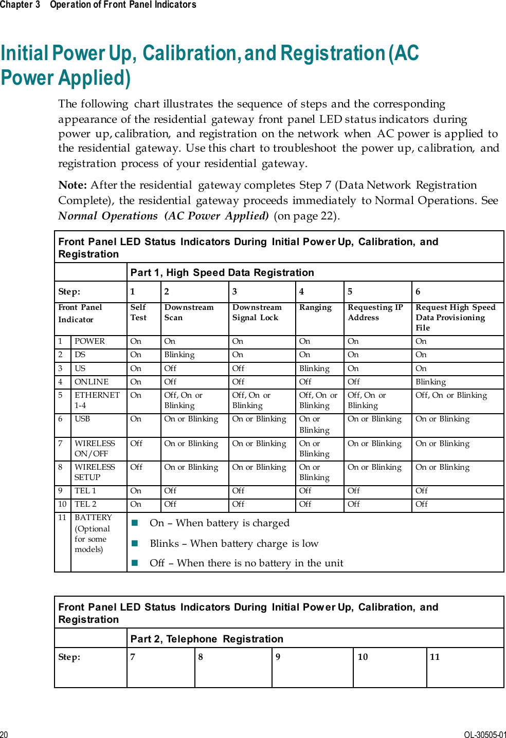
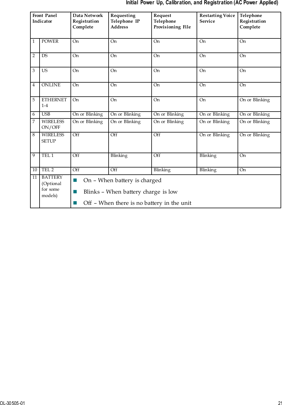
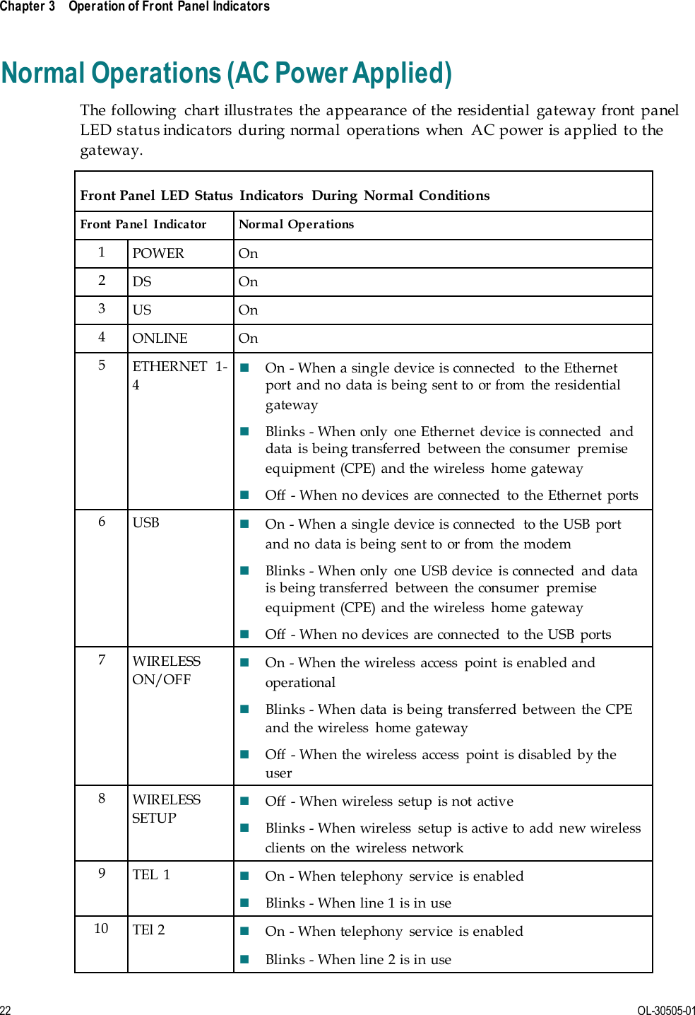
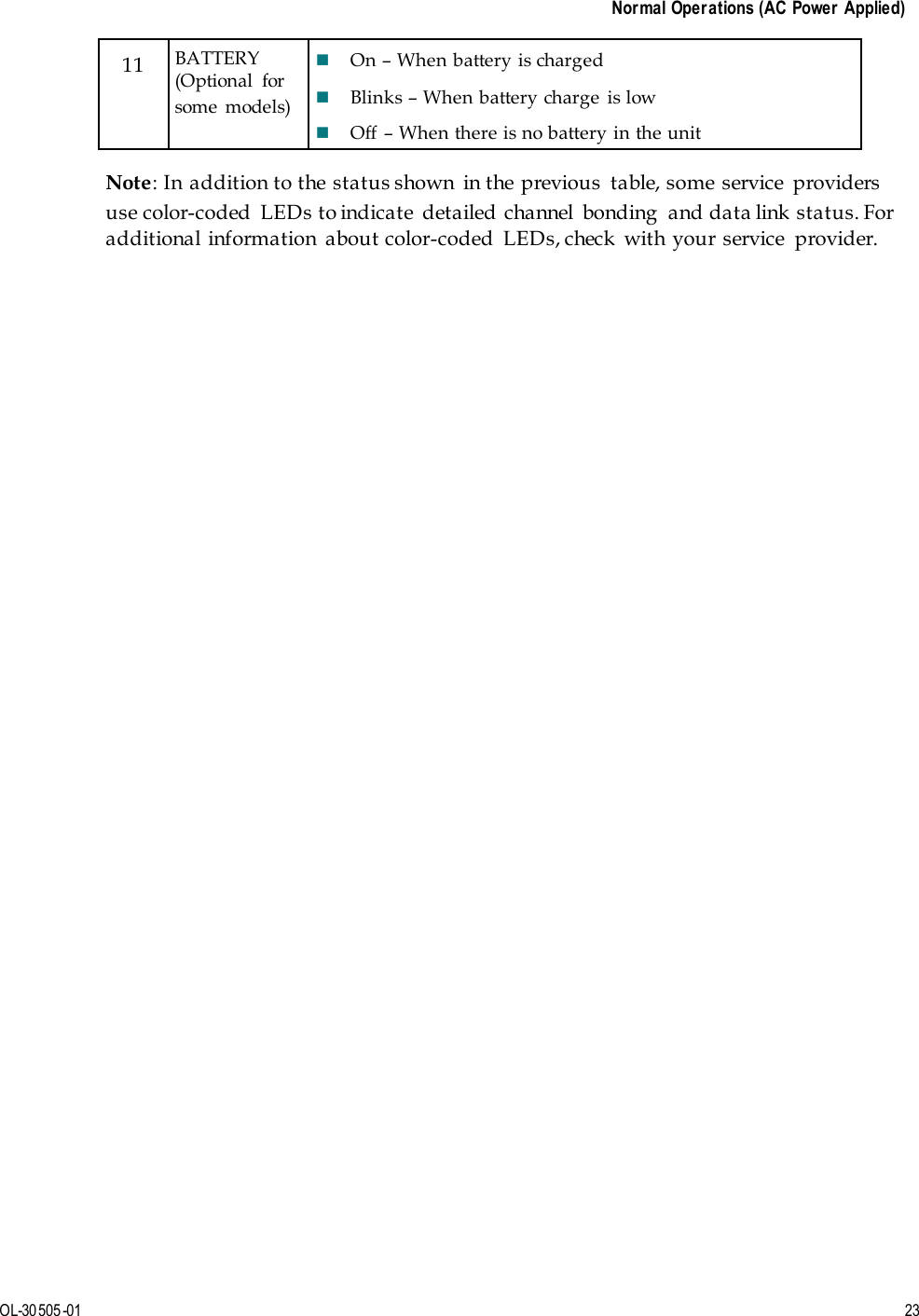
User Manual
user manual
Navigation menu
Upload a User Manual
Namespaces
Wiki Guide
HTML
PDF
Info
Views
User Manual
Discussion / Help
Navigation