PEGATRON WAP571 Wireless-AC/N Premium Dual Radio Access Point with PoE User Manual QSG 571 EN
PEGATRON CORPORATION Wireless-AC/N Premium Dual Radio Access Point with PoE QSG 571 EN
PEGATRON >
User Manual
Quick Start Guide
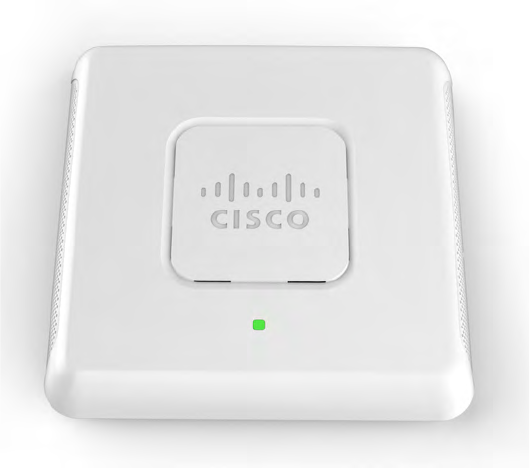
Cisco WAP571 Wireless-AC/N Premium Dual
Radio Access Point with PoE

1 Cisco WAP571 Wireless Access Point
Welcome
Thank you for choosing the Cisco WAP571 Wireless-AC/N Premium Dual
Radio Access Point with PoE. The Cisco WAP571 is an indoor dual radio
802.11ac + 802.11n access point.
This guide is designed to familiarize you with the general layout of the
access point, describe how to deploy the device in your network, and
describe how to configure the device. Your access point has more features
and functionality than what is described in this guide. For additional
information, see the Administration Guide. A link to the Administration
Guide is found in Where to Go From Here, page 12.
Package Contents
•Wireless Access Point
•Mounting kit
•This Quick Start Guide
•Ethernet cable
•Pointer Card with China RoHS
•Technical Support Contacts
•EU Directives 1999/5/EC Compliance Information (for EU SKU only)
Before You Begin
Before you begin the installation, make sure that you have the following
equipment and services:
•A computer with browser support for:
– Internet Explorer v7.0 or later
– Chrome v5.0 or later
– Firefox v3.0 or later
–Safari v3.0 or later
•Tools for installing the hardware
•One or more Ethernet network switches with PoE
1

Cisco WAP571 Wireless Access Point 2
Cisco WAP571 Wireless-AC/N Premium
Dual Radio Access Point with PoE Setup
Features
Front Panel
The front panel of the device consists of a single system LED. For a full
description of the colors of the light and its indications, see Verifying the
Hardware Installation, page 6.
A Kensington lock slot is found under the lights.
Back Panel
The back panel of the device has two RJ-45 Ethernet ports. Facing the
back of the device, the right port (labeled “ETH0/PD”) is an 802.3at &
802.3af Power over Ethernet (PoE) port which is used to power your
device. The left port (labeled “ETH1”) is a general Gigabit Ethernet LAN
interface. Both are auto-sensing, Gigabit Ethernet (802.3) ports used to
connect your WAP devices to network devices, such as computers,
routers, or switches. We strongly recommend that you use a Category
5e or better cable for Gigabit connectivity.
The side panel of the device has a Reset button. See Rebooting the
Devices or Returning them to their Factory Default Settings, page 10
for information on the Reset button.
Default Setting
If you are using a Cisco RV Series router, the default range for the DHCP
assigned address is from 192.168.1.100 to 192.168.1.254. Any device
connecting to the same LAN will be assigned an IP address in this range.
If your network does not have an existing DHCP server, the WAP571 will
start a DHCP server for WLAN stations and stop the DHCP client when
WAP571 is in factory default. The DHCP server will assign the IP address
from 192.168.1.20 to 192.168.1.100.
Parameter Default Value
Username cisco
Password cisco
LAN IP Address DHCP address assigned
by server
Fallback LAN IP 192.168.1.245
Subnetwork Mask 255.255.255.0
2
3 Cisco WAP571 Wireless Access Point
Mounting the Cisco WAP571 Wireless-AC/
N Premium Dual Radio Access Point with
PoE Setup
You can place your access point on a desktop, or mount it on a wall or
ceiling.
Placement Tips
• Ambient Temperature—To prevent the access point from overheating,
do not operate it in an area that exceeds an ambient temperature of
104°F (40°C).
•Air Flow—Both side panels have vents that must be unobstructed to
prevent overheating.
• Mechanical Loading—The device should be level, stable, and secure
to prevent it from sliding or shifting out of position.
Wall and Ceiling Mounting
The Cisco WAP571 device can be wall or ceiling-mounted. A mounting kit
is packaged with your device. The kit is designed to install your device to
the wall or the ceiling.
The mounting bracket has some flexibility so that you can reuse existing
holes drilled for a Cisco WAP551 or WAP561 device. The installer can
remove the Cisco WAP551 or WAP561 and mount the Cisco WAP571.
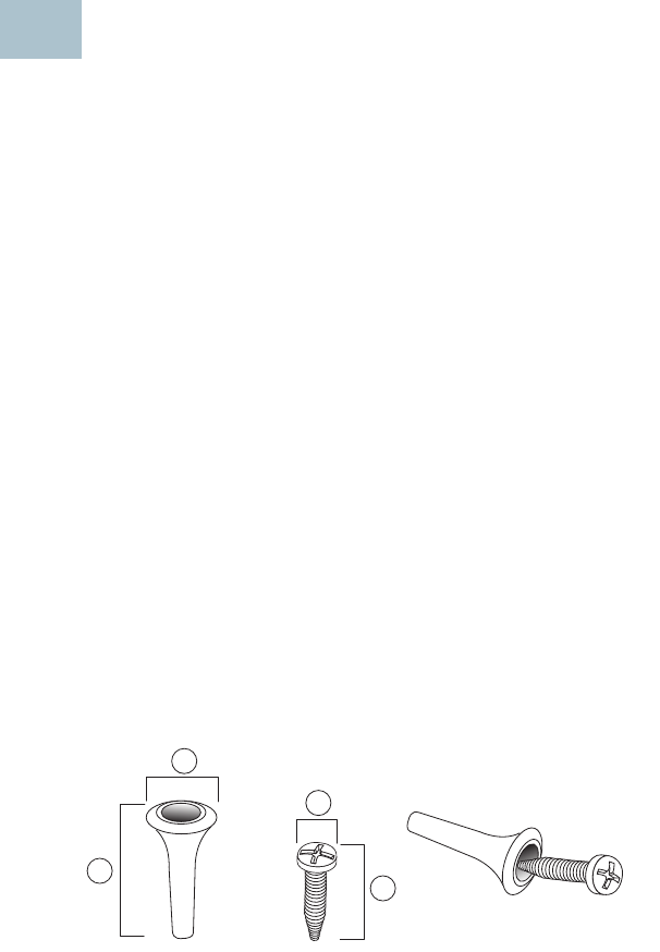
The dimensions for the mount kit screws are as follows:
1.31 to .33 in
(7.8 to 8.3 mm)
2.86 to .88 in (21.8
to 22.3 mm)
3.22 to .24 in
(5.5 to 6.0 mm)
4.69 to .72 in
(17.5 to 18.2
mm)
3
1
24
3
196243

Cisco WAP571 Wireless Access Point 4
WARNING Insecure mounting might damage the device or cause injury.
Cisco is not responsible for damages incurred by insecure wall
or ceiling mounting.
To mount the Cisco WAP 571 device to a wall or ceiling:
STEP 1Determine where you want to mount the device. Verify that the
surface is smooth, flat, dry, and sturdy.
STEP 2Drill two pilot holes into the surface 2.75 inches (70 mm) apart for
your Cisco WAP device.
STEP 3Insert a screw into each hole, leaving a gap between the surface
and the base of the screw head.
STEP 4Place the upper slots of the bracket over the screws, adjust the
screws accordingly, and slide the bracket down until the screws fit
snugly into the slots.
STEP 5Using the bracket as a template, drill two more holes for the lower
screws.
STEP 6Insert a screw into each lower hole.
STEP 7Slide the WAP device into the bracket, placing the cable through
the break-out tab found in the back of the bracket.
Connecting the Cisco WAP571 Wireless-
AC/N Premium Dual Radio Access Point
with PoE Setup
The WiFi default SSID is “Cisco SB-Setup” with the passphrase “cisco123”
in WPA2-PSK AES. This wireless default configuration will not allow traffic
between WiFi and Ethernet; users will need to go through the setup wizard
to resume the traffic between WiFi and Ethernet.
The user can also perform the initial configuration using a wired Ethernet
connection.
To connect the device to the wired network:
STEP 1Connect the Ethernet cable to the Ethernet port of a PoE switch.
STEP 2Connect the other end of the network Ethernet cable to the
Ethernet port (PoE) of the wireless access point.
4

5 Cisco WAP571 Wireless Access Point
NOTE WAP571 bundles the two Ethernet ports to be link
aggregation mode. If the two Ethernet ports have been connected
at the same time, the link partner must also support link
aggregation.
After installation, all lights should be active. Refer to Verifying the
Hardware Installation, page 6 for details about the different lights on each
switch.

Cisco WAP571 Wireless Access Point 6
Verifying the Hardware Installation
To verify the hardware installation, complete the following tasks:
•Check the cable connections.
•Check the state of the indicator lights.
NOTE If you need help resolving a problem, visit the Cisco Support
Community at www.cisco.com/go/smallbizsupport.
Label Activity Description
Power Off The WAP571 is out of power.
Solid (Green) The Cisco WAP571 is normal; no wireless
client connected.
Solid (Blue) The Cisco WAP571 is normal; at least one
wireless client connected.
Flashing (Blue) The Cisco WAP571 is upgrading the firmware.
Solid (Red) The Cisco WAP571 fails to boot with both
firmware images.
LAN Off No Ethernet link; FE Ethernet link is active or
10Mbps.
Solid Green GE Ethernet link is active.
Flashing Green The WAP 571 is transmitting or receiving data.
5

7 Cisco WAP571 Wireless Access Point
Getting Started with the Configuration
To configure the wireless access points, you can either use Ethernet or
wireless. Please follow these steps to access the Wizard and then the
web-based configuration utility from your computer by Ethernet:
STEP 1Ethernet: Connect the wireless access point to the same network
(IP subnet) as your computer. The factory default IP address
configuration of the access points is DHCP. Make sure your DHCP
server is running and can be reached.
See Incorrect IP Address, page 10 for troubleshooting
information, or if you do not have a DHCP server.
Wireless: Search the wireless SSID "CiscoSB-Setup", and connect
to this SSID with the passphrase "cisco123".
STEP 2Locate the IP address of the wireless access point.
a. The wireless access points can be accessed and managed by
Cisco network tools and services including the Cisco FindIT
Network Discovery Utility that enables you to automatically
discover all supported Cisco devices in the same local
network segment as your computer. You can get a snapshot
view of each device or launch the product configuration utility
to view and configure the settings. For more information, see
www.cisco.com/go/findit.
b. The wireless access points are Bonjour-enabled and
automatically broadcast their services and listen for services
being advertised by other Bonjour-enabled devices. If you
have a Bonjour-enabled browser, such as Microsoft Internet
Explorer with a Bonjour plug-in, or the Apple Mac Safari
browser, you can find the wireless access point on your local
network without knowing its IP address.
You can download the complete Bonjour for Microsoft Internet
Explorer browser from Apple’s website by visiting:
http://www.apple.com/bonjour/
c. Locate the IP address assigned by your DHCP server by
accessing your router or DHCP server. See your DHCP server
instructions for more information.
STEP 3Launch a web browser, such as Microsoft Internet Explorer or
Mozilla Firefox.
STEP 4In the Address field, enter the default DHCP address and press the
Enter key.
6

Cisco WAP571 Wireless Access Point 8
STEP 5Enter the default user name of cisco and password of cisco in the
User Name and Password fields.
STEP 6Click Login. The Wireless Access Point Setup Wizard appears.
STEP 7Follow the Setup Wizard instructions to finish the WAP device
installation. We strongly recommend that you use the Setup
Wizard for the first installation.The Setup Wizard turns on the Wi-Fi
radio, which allows you to connect wirelessly. For more advanced
configurations, see the Administration Guide. A link to the
Administration Guide is found in Release the Reset button when
the system light turns on., page 11.
Congratulations, you can now start using your wireless access point.
Suggested Next Steps
Smart PoE
Smart PoE is designed for detecting the power level from the PSE (Power
Sourcing Equipment) side; it does not matter whether 802.3at or 802.3af
mode, the WAP571 will operate at the appropriate mode automatically.
Smart PoE ensures that the WAP571 remains functional once powered by
802.3af PSE, and intelligently to adjust operations below:
•Second Ethernet port disabled
•2.4-GHz 802.11n radio in 2x2:2 spatial-stream mode
•5-GHz 802.11ac radio operates without restrictions
In case of an error while installing, try the following troubleshooting
procedures described in this section:
Troubleshooting
If you cannot display the configuration utility, you can test the ability of the
computer to communicate with the device by using ping.
To u s e ping on a computer running Windows:
7

9 Cisco WAP571 Wireless Access Point
STEP 1Verify that the Cisco WAP571 is powered on and the lights indicate
the appropriate links.
STEP 2Locate the device’s IP address. While there are different ways to
locate your device’s IP address, this procedure uses Cisco FindIT.
a. If you have previously downloaded Cisco FindIT, open Internet
Explorer and launch Cisco FindIT. For more information on
downloading Cisco FindIT, see www.cisco.com/go/findit.
b. In the Cisco FindIT display, place your mouse over the device’s
name. The device IP address is displayed along with other
device information.
STEP 3Open a command window by choosing Start > Run and enter
cmd.
STEP 4At the command window prompt, enter ping and the device IP
address. In this example, we pinged 192.0.2.10.
If successful, you should get a reply similar to the following:
Pinging 192.0.2.10 with 32 bytes of data:
Reply from 192.0.2.10: bytes=32 time<1ms TTL=128
If it fails, you should get a reply similar to the following:
Pinging 192.0.2.10 with 32 bytes of data:
Request timed out.
Possible Cause of Installation Failure
No Power
•Power up the switch and your computer if they are turned off.
•Make sure your PoE switch is powered on and the lights indicate that
you have a link. See Verifying the Hardware Installation, page 6.
•Verify that the devices on your network are not plugged into a
switchable outlet.
Bad Ethernet Connection
•Check the state of the indicator lights. See Verifying the Hardware
Installation, page 6.
•Check the Ethernet cable to ensure that it is firmly connected to your
devices. Devices connected by the Ethernet cable can include the WAP
device, and routers, any switches, and your computer.
•Verify the connected switch has auto-negotiation enabled. The access
point and the switch need the same negotiation parameters set.

Cisco WAP571 Wireless Access Point 10
Bad Image
After a new firmware installation, if the Power light is solid red, contact
system support; see Release the Reset button when the system light
turns on., page 11.
Incorrect IP Address
The most likely cause of connectivity failure is an incorrect IP address. The
Web browser may be pointing to the wrong IP address, or your computer
may be configured with an IP address that is not in the same subnet as the
device.
Because the factory default IP address configuration is DHCP, make sure
that your DHCP server is running and can be reached. You may need to
disconnect and reconnect the devices for them to discover their new IP
addresses from the DHCP server. You can then query the DHCP server for
the new IP address. See Step 2 of Getting Started with the
Configuration, page 7 for more information on how to find the DHCP
address.
If the wireless access points do not receive a DHCP response (there is no
DHCP server on your network) after 60 seconds, the access points will
fallback to the following default static IP address: 192.168.1.245 and a
default mask of 255.255.255.0. To reach that IP address, be sure that your
computer is on the 192.168.1.xxx network.
Rebooting the Devices or Returning them
to their Factory Default Settings
To reboot your device:
•The Cisco WAP571 uses PoE power supply; unplug your Ethernet
connection and plug it back in.
or
•With the power on, press the Reset button with an opened paper clip
for less than three seconds, or until the lights go off.
– When all the lights go off, release the Reset button.
– Release the Reset button as soon as the lights go off, or you will
restore the device to factory default settings and lose your
configurations.
8
11 Cisco WAP571 Wireless Access Point
•Release the Reset button when the system light turns on.

Cisco WAP571 Wireless Access Point 12
Where to Go From Here
Support
Cisco Support
Community
www.cisco.com/go/smallbizsupport
Cisco Support and
Resources
www.cisco.com/go/smallbizhelp
Phone Support Contacts www.cisco.com/en/US/support/
tsd_cisco_small_business
_support_center_contacts.html
Cisco Firmware
Downloads
www.cisco.com/go/smallbizfirmware
Select a link to download firmware for Cisco
Products. No login is required.
Cisco Open Source
Requests
www.cisco.com/go/
smallbiz_opensource_request
Cisco Partner Central
(Partner Login Required)
www.cisco.com/web/partners/sell/smb
Product Documentation
Cisco WAP571
Administration Guide
www.cisco.com/go/300_wap_resources
Cisco Power Adapters www.cisco.com/go/wap_accessories

Americas Headquarters
Cisco Systems, Inc.
www.cisco.com
Cisco has more than 200 offices worldwide.
Addresses, phone numbers, and fax numbers
are listed on the Cisco website at
www.cisco.com/go/offices.
Cisco and the Cisco logo are trademarks or registered trademarks of Cisco and/or its affiliates
in the U.S. and other countries. To view a list of Ciscotrademarks, go to this URL:
www.cisco.com/go/trademarks. Third-party trademarks mentioned are the property of their
respective owners. The use of the word partner does not imply a partnership relationship
between Cisco and any other company. (1110R)
© 2015 Cisco Systems, Inc. All rights reserved.
78-21544-02A0
To reset the device to factory default settings:
•With the power on, press and hold the Reset button with an opened
paper clip for more than 10 seconds. The system light will go off.

Americas Headquarters:
Cisco Systems, Inc., 170 West Tasman Drive, San Jose, CA 95134-1706 USA
Regulatory Compliance and Safety
Information for the Cisco WAP571/571E
Wireless Access Point (EMC Class B Devices)
This document provides domestic and international regulatory compliance and safety information for the
Cisco WAP571/571E Wireless Access Point EMC Class B Devices.
Use this document in conjunction with the documentation available online for the Wireless Access
Points.
This document includes the following sections:
• Translated Safety Warnings, page 1
• Product Usage Restrictions, page 22
• Declaration of Conformity Statements, page 22
• European Directives, page 22
• EU Battery Disposal and Recycling, page 24
• Standards Compliance, page 24
• EMC Class B Notices and Warnings, page 25
• Japanese Electric Appliance and Radio Laws, page 28
• Radio, page 28
• Canadian Radio Warning Statement, page 28
• Generic Discussion on RF Exposure, page 31
• Obtaining Documentation and Submitting a Service Request, page 32
Translated Safety Warnings
This section includes translations in multiple languages of the warnings that may appear in your product
documents.
• Statement 1071—Warning Definition
2
Regulatory Compliance and Safety Information for the Cisco WAP571/571E Wireless Access Point (EMC Class B Devices)
78-20515-02
Translated Safety Warnings
• Statement 1—Power Disconnection Warning
• Statement 248—Unit Mounting Warning
• Statement 1004—Installation Instructions
• Statement 1005—Circuit Breaker
• Statement 1040—Product Disposal
• Statement 1044—Port Connections
• Statement 1072—Shock Hazard from Interconnections
• Statement 1073—No User-Serviceable Parts
• Statement 1074—Comply with Local and National Electrical Codes
Statement 1071—Warning Definition
Warning
IMPORTANT SAFETY INSTRUCTIONS
This warning symbol means danger. You are in a situation that could cause bodily injury. Before
you work on any equipment, be aware of the hazards involved with electrical circuitry and be
familiar with standard practices for preventing accidents. Use the statement number provided
at the end of each warning to locate its translation in the translated safety warnings that
accompanied this device.
Statement 1071
SAVE THESE INSTRUCTIONS
Waarschuwing
BELANGRIJKE VEILIGHEIDSINSTRUCTIES
Dit waarschuwingssymbool betekent gevaar. U verkeert in een situatie die lichamelijk letsel kan
veroorzaken. Voordat u aan enige apparatuur gaat werken, dient u zich bewust te zijn van de
bij elektrische schakelingen betrokken risico's en dient u op de hoogte te zijn van de standaard
praktijken om ongelukken te voorkomen. Gebruik het nummer van de verklaring onderaan de
waarschuwing als u een vertaling van de waarschuwing die bij het apparaat wordt geleverd,
wilt raadplegen.
BEWAAR DEZE INSTRUCTIES
Varoitus
TÄRKEITÄ TURVALLISUUSOHJEITA
Tämä varoitusmerkki merkitsee vaaraa. Tilanne voi aiheuttaa ruumiillisia vammoja. Ennen
kuin käsittelet laitteistoa, huomioi sähköpiirien käsittelemiseen liittyvät riskit ja tutustu
onnettomuuksien yleisiin ehkäisytapoihin. Turvallisuusvaroitusten käännökset löytyvät
laitteen mukana toimitettujen käännettyjen turvallisuusvaroitusten joukosta varoitusten
lopussa näkyvien lausuntonumeroiden avulla.
SÄILYTÄ NÄMÄ OHJEET

3
Regulatory Compliance and Safety Information for the Cisco WAP571/571E Wireless Access Point (EMC Class B Devices)
78-20515-02
Translated Safety Warnings
Attention
IMPORTANTES INFORMATIONS DE SÉCURITÉ
Ce symbole d'avertissement indique un danger. Vous vous trouvez dans une situation pouvant
entraîner des blessures ou des dommages corporels. Avant de travailler sur un équipement,
soyez conscient des dangers liés aux circuits électriques et familiarisez-vous avec les procédures
couramment utilisées pour éviter les accidents. Pour prendre connaissance des traductions des
avertissements figurant dans les consignes de sécurité traduites qui accompagnent cet appareil,
référez-vous au numéro de l'instruction situé à la fin de chaque avertissement.
CONSERVEZ CES INFORMATIONS
Warnung
WICHTIGE SICHERHEITSHINWEISE
Dieses Warnsymbol bedeutet Gefahr. Sie befinden sich in einer Situation, die zu Verletzungen
führen kann. Machen Sie sich vor der Arbeit mit Geräten mit den Gefahren elektrischer
Schaltungen und den üblichen Verfahren zur Vorbeugung vor Unfällen vertraut. Suchen Sie mit
der am Ende jeder Warnung angegebenen Anweisungsnummer nach der jeweiligen
Übersetzung in den übersetzten Sicherheitshinweisen, die zusammen mit diesem Gerät
ausgeliefert wurden.
BEWAHREN SIE DIESE HINWEISE GUT AUF.
Avvertenza
IMPORTANTI ISTRUZIONI SULLA SICUREZZA
Questo simbolo di avvertenza indica un pericolo. La situazione potrebbe causare infortuni alle
persone. Prima di intervenire su qualsiasi apparecchiatura, occorre essere al corrente dei
pericoli relativi ai circuiti elettrici e conoscere le procedure standard per la prevenzione di
incidenti. Utilizzare il numero di istruzione presente alla fine di ciascuna avvertenza per
individuare le traduzioni delle avvertenze riportate in questo documento.
CONSERVARE QUESTE ISTRUZIONI
Advarsel
VIKTIGE SIKKERHETSINSTRUKSJONER
Dette advarselssymbolet betyr fare. Du er i en situasjon som kan føre til skade på person. Før
du begynner å arbeide med noe av utstyret, må du være oppmerksom på farene forbundet med
elektriske kretser, og kjenne til standardprosedyrer for å forhindre ulykker. Bruk nummeret i
slutten av hver advarsel for å finne oversettelsen i de oversatte sikkerhetsadvarslene som fulgte
med denne enheten.
TA VARE PÅ DISSE INSTRUKSJONENE
Aviso
INSTRUÇÕES IMPORTANTES DE SEGURANÇA
Este símbolo de aviso significa perigo. Você está em uma situação que poderá ser causadora de
lesões corporais. Antes de iniciar a utilização de qualquer equipamento, tenha conhecimento
dos perigos envolvidos no manuseio de circuitos elétricos e familiarize-se com as práticas
habituais de prevenção de acidentes. Utilize o número da instrução fornecido ao final de cada
aviso para localizar sua tradução nos avisos de segurança traduzidos que acompanham este
dispositivo.
GUARDE ESTAS INSTRUÇÕES
4
Regulatory Compliance and Safety Information for the Cisco WAP571/571E Wireless Access Point (EMC Class B Devices)
78-20515-02
Translated Safety Warnings
¡Advertencia!
INSTRUCCIONES IMPORTANTES DE SEGURIDAD
Este símbolo de aviso indica peligro. Existe riesgo para su integridad física. Antes de manipular
cualquier equipo, considere los riesgos de la corriente eléctrica y familiarícese con los
procedimientos estándar de prevención de accidentes. Al final de cada advertencia encontrará
el número que le ayudará a encontrar el texto traducido en el apartado de traducciones que
acompaña a este dispositivo.
GUARDE ESTAS INSTRUCCIONES
Varning!
VIKTIGA SÄKERHETSANVISNINGAR
Denna varningssignal signalerar fara. Du befinner dig i en situation som kan leda till
personskada. Innan du utför arbete på någon utrustning måste du vara medveten om farorna
med elkretsar och känna till vanliga förfaranden för att förebygga olyckor. Använd det nummer
som finns i slutet av varje varning för att hitta dess översättning i de översatta
säkerhetsvarningar som medföljer denna anordning.
SPARA DESSA ANVISNINGAR
5
Regulatory Compliance and Safety Information for the Cisco WAP571/571E Wireless Access Point (EMC Class B Devices)
78-20515-02
Translated Safety Warnings
Aviso
INSTRUÇÕES IMPORTANTES DE SEGURANÇA
Este símbolo de aviso significa perigo. Você se encontra em uma situação em que há risco de
lesões corporais. Antes de trabalhar com qualquer equipamento, esteja ciente dos riscos que
envolvem os circuitos elétricos e familiarize-se com as práticas padrão de prevenção de
acidentes. Use o número da declaração fornecido ao final de cada aviso para localizar sua
tradução nos avisos de segurança traduzidos que acompanham o dispositivo.
GUARDE ESTAS INSTRUÇÕES
Advarsel
VIGTIGE SIKKERHEDSANVISNINGER
Dette advarselssymbol betyder fare. Du befinder dig i en situation med risiko for
legemesbeskadigelse. Før du begynder arbejde på udstyr, skal du være opmærksom på de
involverede risici, der er ved elektriske kredsløb, og du skal sætte dig ind i standardprocedurer
til undgåelse af ulykker. Brug erklæringsnummeret efter hver advarsel for at finde
oversættelsen i de oversatte advarsler, der fulgte med denne enhed.
GEM DISSE ANVISNINGER
6
Regulatory Compliance and Safety Information for the Cisco WAP571/571E Wireless Access Point (EMC Class B Devices)
78-20515-02
Translated Safety Warnings
7
Regulatory Compliance and Safety Information for the Cisco WAP571/571E Wireless Access Point (EMC Class B Devices)
78-20515-02
Translated Safety Warnings
Statement 1—Power Disconnection Warning
Warning
Before working on a system that has an on/off switch, turn OFF the power and unplug the power
cord.
Waarschuwing
Voordat u aan een systeem werkt dat een aan/uit schakelaar heeft, dient u de stroomvoorziening
UIT te schakelen en de stekker van het netsnoer uit het stopcontact te halen.
8
Regulatory Compliance and Safety Information for the Cisco WAP571/571E Wireless Access Point (EMC Class B Devices)
78-20515-02
Translated Safety Warnings
Varoitus
Ennen kuin teet mitään sellaiselle järjestelmälle, jossa on kaksiasentokytkin, katkaise siitä
virta ja kytke virtajohto irti.
Attention
Avant de travailler sur un système équipé d'un commutateur marche-arrêt, mettre l'appareil à
l'arrêt (OFF) et débrancher le cordon d'alimentation.
Warnung
Bevor Sie an einem System mit Ein/Aus-Schalter arbeiten, schalten Sie das System AUS und
ziehen das Netzkabel aus der Steckdose.
Avvertenza
Prima di lavorare su un sistema dotato di un interruttore on/off, spegnere (OFF) il sistema e
staccare il cavo dell’alimentazione.
Advarsel
Slå AV strømmen og trekk ut strømledningen før det utføres arbeid på et system som er utstyrt
med en av/på-bryter.
Aviso
Antes de começar a trabalhar num sistema que tem um interruptor on/off, DESLIGUE a
corrente eléctrica e retire o cabo de alimentação da tomada.
¡Advertencia!
Antes de utilizar cualquier sistema equipado con interruptor de Encendido/Apagado
(ON/OFF), cortar la alimentación y desenchufar el cable de alimentación.
Varning!
Slå AV strömmen och dra ur nätsladden innan du utför arbete på ett system med strömbrytare.

9
Regulatory Compliance and Safety Information for the Cisco WAP571/571E Wireless Access Point (EMC Class B Devices)
78-20515-02
Translated Safety Warnings
Statement 248—Unit Mounting Warning
Warning
This unit is intended to be mounted on a wall. Please read the wall mounting instructions
carefully before beginning installation. Failure to use the correct hardware or to follow the
correct procedures could result in a hazardous situation to people and damage to the system.
Waarschuwing
Deze eenheid dient aan een wand te worden bevestigd. Lees voordat u met de installatie begint,
de instructies voor wandmontage aandachtig door. Het niet gebruiken van de juiste apparatuur
of het niet volgen van de juiste procedures kan leiden tot gevaarlijke situaties of beschadiging
van het systeem.
Varoitus
Tämä laite on tarkoitettu seinälle asennettavaksi. Lue seinäasennusohjeet huolellisesti ennen
asennuksen aloittamista. Väärien työkalujen käyttäminen tai ohjeiden noudattamatta
jättäminen voi aiheuttaa henkilövahinkoja ja vioittaa laitetta.
Attention
Cette unité est conçue pour être montée sur un mur. Veuillez lire attentivement les instructions
de montage avant de commencer l'installation. L'utilisation d'un matériel incorrect ou
l'application inappropriée des procédures peut être à l'origine d'accidents et endommager le
système.
Warnung
Diese Einheit ist für die Montage an einer Wand bestimmt. Lesen Sie die Montageanweisungen
sorgfältig durch, bevor Sie mit der Installation beginnen. Nichtverwenden der korrekten
Hardware oder Nichtbefolgen der korrekten Vorgehensweise stellt eine potentielle
Gefahrenquelle dar und könnte das System beschädigen.
Avvertenza
L’unità deve essere montata a parete. Leggere attentamente le istruzioni di montaggio a parete
prima di procedere all’installazione. L’impiego di utensili non adeguati o di procedure non
corrette può comportare un rischio per le persone e per il sistema stesso.
Advarsel
Denne enheten er beregnet på veggmontering. Les instruksjonene om veggmontering nøye før
du begynner installeringen. Hvis du ikke bruker riktig maskinutstyr eller følger de korrekte
prosedyrer, kan det medføre risiko for personskade og skade på systemet.
Aviso
Esta unidade foi concebida para ser montada numa parede. Leia atentamente as instruções de
montagem em parede antes de iniciar a instalação. A utilização de material incorrecto ou o não
seguimento dos procedimentos correctos podem dar origem a uma situação perigosa para o
pessoal e danificar o sistema.
¡Advertencia!
Esta unidad está diseñada para ser montada en la pared. Leer las instrucciones de montaje en
pared cuidadosamente antes de comenzar la instalación. En caso de no utilizar los materiales
apropiados o no seguir el procedimiento correcto, se podría crear una situación peligrosa y
ocasionar daños al sistema.
Varning!
Den här enheten är utformad för väggmontering. Läs noga anvisningarna för väggmontering
innan du börjar installera. Om du inte använder rätt maskinvara eller inte följer anvisningarna
kan det orsaka fara för personskada eller skador på systemet.
10
Regulatory Compliance and Safety Information for the Cisco WAP571/571E Wireless Access Point (EMC Class B Devices)
78-20515-02
Translated Safety Warnings
Statement 1004—Installation Instructions
Warning
Read the installation instructions before connecting the system to the power source.
Statement
1004
Waarschuwing
Raadpleeg de installatie-instructies voordat u het systeem op de voedingsbron aansluit.
Varoitus
Lue asennusohjeet ennen järjestelmän yhdistämistä virtalähteeseen.
Attention
Avant de brancher le système sur la source d'alimentation, consulter les directives
d'installation.
Warnung
Vor dem Anschließen des Systems an die Stromquelle die Installationsanweisungen lesen.
Avvertenza
Consultare le istruzioni di installazione prima di collegare il sistema all'alimentatore.
Advarsel
Les installasjonsinstruksjonene før systemet kobles til strømkilden.
Aviso
Leia as instruções de instalação antes de ligar o sistema à fonte de energia.
¡Advertencia!
Lea las instrucciones de instalación antes de conectar el sistema a la red de alimentación.
Varning!
Läs installationsanvisningarna innan du kopplar systemet till strömförsörjningsenheten.
11
Regulatory Compliance and Safety Information for the Cisco WAP571/571E Wireless Access Point (EMC Class B Devices)
78-20515-02
Translated Safety Warnings
Statement 1005—Circuit Breaker
Warning
This product relies on the building’s installation for short-circuit (overcurrent) protection.
Ensure that the protective device is rated not greater than:
15 A, 125 Vac
, or 10A, 240 Vac.
Statement 1005
Waarschuwing
Dit product is afhankelijk van de installatie van het gebouw voor beveiliging tegen kortsluiting
(overstroom). Controleer of de beschermingsinrichting niet meer dan:
15 A, 125 Vac
, or 10A, 240 Vac is.
Varoitus
Tämä tuote on riippuvainen rakennukseen asennetusta oikosulkusuojauksesta
(ylivirtasuojauksesta). Varmista, että suojalaitteen mitoitus ei ole yli:
15 A, 125 Vac
, or 10A, 240 Vac.
Attention
Pour ce qui est de la protection contre les courts-circuits (surtension), ce produit dépend de
l'installation électrique du local. Vérifiez que le courant nominal du dispositif de protection
n'est pas supérieur à :
15 A, 125 Vac
, or 10A, 240 Vac.
Warnung
Dieses Produkt ist darauf angewiesen, dass im Gebäude ein Kurzschluss- bzw. Überstromschutz
installiert ist. Stellen Sie sicher, dass der Nennwert der Schutzvorrichtung nicht mehr als:
15 A, 125 Vac
, or 10A, 240 Vac beträgt.
Avvertenza
Questo prodotto dipende dall'impianto dell'edificio per quanto riguarda la protezione contro
cortocircuiti (sovracorrente). Assicurarsi che il dispositivo di protezione non abbia un rating
superiore a:
15 A, 125 Vac
, or 10A, 240 Vac.
Advarsel
Dette produktet er avhengig av bygningens installasjoner av kortslutnings
(overstrøm)-beskyttelse. Påse at verneenheten ikke er merket høyere enn:
15 A, 125 Vac
, or 10A, 240 Vac.
12
Regulatory Compliance and Safety Information for the Cisco WAP571/571E Wireless Access Point (EMC Class B Devices)
78-20515-02
Translated Safety Warnings
Statement 1040—Product Disposal
Aviso
Este produto depende das instalações existentes para proteção contra curto-circuito
(sobrecarga). Assegure-se de que o fusível ou disjuntor não seja superior a:
15 A, 125 Vac
, or 10A, 240 Vac.
¡Advertencia!
Este equipo utiliza el sistema de protección contra cortocircuitos (o sobrecorrientes) del edificio.
Asegúrese de que el dispositivo de protección no sea superior a:
15 A, 125 Vac
, or 10A, 240 Vac.
Varning!
Denna produkt är beroende av i byggnaden installerat kortslutningsskydd (överströmsskydd).
Kontrollera att skyddsanordningen inte har högre märkvärde än:
15 A, 125 Vac
, or 10A, 240 Vac.
15 A, 125 Vac
, or 10A, 240 Vac.
15 A, 125 Vac
, or 10A, 240 Vac.
15 A, 125 Vac
, or 10A, 240 Vac.
15 A, 125 Vac
, or 10A, 240 Vac.
Warning
Ultimate disposal of this product should be handled according to all national laws and
regulations.
Statement 1040
Waarschuwing
Het uiteindelijke wegruimen van dit product dient te geschieden in overeenstemming met alle
nationale wetten en reglementen.
Varoitus
Tämä tuote on hävitettävä kansallisten lakien ja määräysten mukaisesti.
Attention
La mise au rebut ou le recyclage de ce produit sont généralement soumis à des lois et/ou
directives de respect de l'environnement. Renseignez-vous auprès de l'organisme compétent.
Warnung
Die Entsorgung dieses Produkts sollte gemäß allen Bestimmungen und Gesetzen des Landes
erfolgen.
13
Regulatory Compliance and Safety Information for the Cisco WAP571/571E Wireless Access Point (EMC Class B Devices)
78-20515-02
Translated Safety Warnings
Avvertenza
Lo smaltimento di questo prodotto deve essere eseguito secondo le leggi e regolazioni locali.
Advarsel
Endelig kassering av dette produktet skal være i henhold til alle relevante nasjonale lover og
bestemmelser.
Aviso
Deitar fora este produto em conformidade com todas as leis e regulamentos nacionais.
¡Advertencia!
Al deshacerse por completo de este producto debe seguir todas las leyes y reglamentos
nacionales.
Varning!
Vid deponering hanteras produkten enligt gällande lagar och bestämmelser.
Aviso
O descarte definitivo deste produto deve estar de acordo com todas as leis e regulamentações
nacionais.
Advarsel
Endelig bortskaffelse af dette produkt skal ske i henhold til gældende love og regler.
14
Regulatory Compliance and Safety Information for the Cisco WAP571/571E Wireless Access Point (EMC Class B Devices)
78-20515-02
Translated Safety Warnings
Statement 1044—Port Connections
Warning
For connections outside the building where the equipment is installed, the following ports must
be connected through an approved network termination unit with integral circuit protection.
10/100/1000 Ethernet
Statement 1044
Waarschuwing
Voor aansluitingen buiten het gebouw waar de apparatuur wordt geïnstalleerd, dienen de
volgende poorten aangesloten te worden via een goedgekeurde netwerkafsluiteenheid met
integrale circuitbescherming.
10/100/1000 Ethernet
Varoitus
Asennuksen sisältävän rakennuksen ulkopuolisia liitäntöjä varten seuraavat portit on
kytkettävä hyväksytyn verkon päätelaitteen kautta ja virtapiirin on oltava kiinteästi suojattu.
10/100/1000 Ethernet
Attention
Pour les connexions extérieures au bâtiment équipé, les ports suivants doivent être connectés à
un point approuvé de terminaison de réseau, avec protection complète du circuit.
10/100/1000 Ethernet
Warnung
Für Verbindungen außerhalb des Gebäudes, in dem das Gerät installiert ist, müssen die folgenden
Anschlüsse über eine zulässige Netzabschlusseinheit mit integralem Leitungsschutz verbunden werden.
10/100/1000 Ethernet
Avvertenza
Per le connessioni esterne all'edificio in cui è installato l'apparecchio, le seguenti porte devono
essere connesse a un'unità di terminazione di rete approvata, con protezione completa del
circuito.
10/100/1000 Ethernet
Advarsel
For tilkoblinger utenfor bygningen der utstyret er montert, må følgende åpninger tilkobles
gjennom en godkjent nettverksterminal med integrert kretsbeskyttelse.
10/100/1000 Ethernet
15
Regulatory Compliance and Safety Information for the Cisco WAP571/571E Wireless Access Point (EMC Class B Devices)
78-20515-02
Translated Safety Warnings
Aviso
Para ligações fora do edifício onde o equipamento está instalado, é necessário ligar as seguintes
portas através de uma unidade de terminal de rede aprovada com protecção de circuito integral.
10/100/1000 Ethernet
¡Advertencia!
Para realizar conexiones en el exterior del edificio en el que esté instalado el equipo, deberá
conectar los puertos especificados a continuación a una unidad terminal de red aprobada que
cuente con protección de circuitos integrales.
10/100/1000 Ethernet
Varning!
För alla anslutningar utanför byggnaden där utrustningen har installerats gäller att följande
portar måste anslutas genom en godkänd nätverksavslutningsenhet med integrerat kretsskydd.
10/100/1000 Ethernet
10/100/1000 Ethernet
10/100/1000 Ethernet
10/100/1000 Ethernet
10/100/1000 Ethernet
10/100/1000 Ethernet
10/100/1000 Ethernet
10/100/1000 Ethernet
10/100/1000 Ethernet
16
Regulatory Compliance and Safety Information for the Cisco WAP571/571E Wireless Access Point (EMC Class B Devices)
78-20515-02
Translated Safety Warnings
Statement 1072—Shock Hazard from Interconnections
10/100/1000 Ethernet
10/100/1000 Ethernet
10/100/1000 Ethernet
Warning
Voltages that present a shock hazard may exist on Power over Ethernet (PoE) circuits if
interconnections are made using uninsulated exposed metal contacts, conductors, or terminals.
Avoid using such interconnection methods, unless the exposed metal parts are located within a
restricted access location and users and service people who are authorized within the restricted
access location are made aware of the hazard. A restricted access area can be accessed only
through the use of a special tool, lock and key or other means of security.
Statement 1072
Waarschuwing
Voltages kunnen elektrische schokken veroorzaken in PoE (Power over Ethernet)-circuits als er
verbindingen worden gemaakt met blootliggende metalen contactpunten, geleiders of
aansluitingspunten die niet zijn geïsoleerd. Gebruik dit type verbinding niet tenzij de
blootliggende metalen onderdelen zich bevinden op een locatie met beperkte toegang en de
gebruikers en onderhoudstechnici die toegang tot deze locatie hebben, op het gevaar worden
gewezen. De locatie met beperkte toegang kan alleen worden geopend met speciaal gereedschap,
slot en sleutel of een andere beveiligingsmethode.
Varoitus
Sisäisissä Ethernet (PoE) -virtapiireissä voi olla sähköiskun vaaran aiheuttavia jännitteitä, jos
kytkentöihin käytetään eristämättömiä paljaita metalliliittimiä tai -johtimia. Vältä tällaisia
kytkentöjä, elleivät paljaat metalliosat ole rajatussa paikassa. Ilmoita valtuutetuille käyttäjille
ja huoltohenkilöille vaarasta. Rajattuun alueeseen pääsee käsiksi ainoastaan erityistyökalua,
lukkoa ja avainta tai muuta turvallista menetelmää käyttämällä.

17
Regulatory Compliance and Safety Information for the Cisco WAP571/571E Wireless Access Point (EMC Class B Devices)
78-20515-02
Translated Safety Warnings
Attention
Les tensions existant sur les alimentations utilisant la technologie PoE (Power over Ethernet)
peuvent constituer un risque d'électrocution si les interconnexions sont effectuées en utilisant
des terminaux, conducteurs ou contacts métalliques exposés non isolés. Évitez d'utiliser de telles
méthodes d'interconnexion à moins que les pièces métalliques exposées ne se trouvent dans un
emplacement d'accès restreint et que les utilisateurs et les responsables du service autorisés
dans cet emplacement d'accès restreint ne soient conscients du danger. Une zone d'accès
restreint peut être accédée uniquement à l'aide d'une clé, d'un outil et d'un verrou spécial, ou
d'autres moyens de sécurité.
Warnung
Bei Power-over-Ethernet-(PoE-)Schaltkreisen besteht u.U. Stromschlaggefahr, wenn
Verbindungen unter Verwendung nicht isolierter, freiliegender Metallkontakte, Leiter oder
Anschlussklemmen hergestellt werden. Vermeiden Sie das Herstellen solcher Verbindungen, es
sei denn, die freiliegenden Metallteile befinden sich an Orten mit beschränktem Zugang, und
Personen, die Zugang dazu haben, sind ausdrücklich über diese Gefahr informiert worden. Ein
Ort mit beschränktem Zugang ist nur mit Hilfe eines speziellen Werkzeugs, Schloss und
Schlüssels oder anderen Sicherheitseinrichtungen zugänglich.
Avvertenza
Nei circuiti con alimentazione via Ethernet (PoE) possono verificarsi pericoli di scosse elettriche
se si creano connessioni con contatti metallici, conduttori o terminali scoperti. Evitare di
utilizzare i metodi di connessione sopraelencati a meno che le parti metalliche esposte non si
trovino in una zona riservata e gli utenti e il personale di assistenza, che sono autorizzati ad
accedere nella suddetta zona, siano stati messi al corrente del pericolo. È possibile accedere alla
zona riservata solamente utilizzando gli appositi elementi di sicurezza.
Advarsel
I strømkretser med PoE (Power over Ethernet) kan det være spenninger som kan utgjøre
støtfare hvis det blir foretatt sammenkoblinger med uisolerte, eksponerte kontakter, ledere
eller terminaler av metall. Unngå å bruke slike sammenkoblingsmetoder med mindre de
eksponerte metalldelene er i et område med begrenset tilgang, og brukere og servicepersonell
som har tilgang til det begrensede området, blir gjort oppmerksom på faren. Et område med
begrenset tilgang kan bare åpnes ved hjelp av spesialverktøy, nøkkel eller andre
sikkerhetstiltak.
Aviso
Pode haver voltagens que representam perigo de choque em circuitos PoE (Power over
Ethernet) se as interconexões forem feitas utilizando-se terminais, condutores ou contatos de
metal exposto e sem isolamento. Evite utilizar tais métodos de interconexão a não ser que as
partes de metal expostas estejam em um local de acesso restrito e os usuários e o pessoal de
serviço com acesso autorizado a este local restrito estejam cientes do perigo. Uma área de acesso
restrito só pode ser acessada com o uso de uma ferramenta, fechadura e chave especial ou de
outros meios de segurança.
¡Advertencia!
Puede haber voltajes con riesgo de shock en circuitos de alimentación sobre el cableado
Ethernet (PoE), si para las interconexiones se utilizan contactos, conductores o terminales
metálicos descubiertos. Evite tales métodos de interconexión, a menos que las partes metálicas
descubiertas se encuentren en un lugar de acceso restringido y tanto los usuarios como el
personal de servicios en dicho lugar sean conscientes de la existencia de tal riesgo. Sólo se puede
tener acceso a una zona de acceso restringido mediante el uso de una herramienta especial, un
candado y una llave u otros medios de seguridad.
18
Regulatory Compliance and Safety Information for the Cisco WAP571/571E Wireless Access Point (EMC Class B Devices)
78-20515-02
Translated Safety Warnings
Statement 1073—No User-Serviceable Parts
Varning!
Det kan finnas spänningar på PoE-kretsarna (Power over Ethernet) som utgör risk för stötar
om sammankopplingarna görs med ej isolerade, exponerade kontakter, ledare och/eller
terminaler av metall. Undvik att använda sådana sammankopplingsmetoder, såvida inte de
exponerade metalldelarna finns i en plats med begränsad åtkomst. Användare och
servicepersonal som tillåts inom platsen med begränsad åtkomst måste vara medvetna om
risken. Ett begränsat område kan bara nås med ett speciellt verktyg eller lås, en speciell nyckel
eller någon annan säkerhetsmetod.
Warning
No user-serviceable parts inside. Do not open.
Statement 1073
Waarschuwing
Er zijn geen door de gebruiker te vervangen onderdelen. Niet openen.
19
Regulatory Compliance and Safety Information for the Cisco WAP571/571E Wireless Access Point (EMC Class B Devices)
78-20515-02
Translated Safety Warnings
Varoitus
Ei sisällä käyttäjän huollettavissa olevia osia. Älä avaa.
Attention
Aucune pièce se trouvant à l'intérieur ne peut être réparée ou remplacée par l'utilisateur. Ne
pas ouvrir.
Warnung
Enthält keine Teile, die vom Benutzer gewartet werden müssen. Bitte nicht öffnen.
Avvertenza
Non contiene parti riparabili dall'utente. Non aprire.
Advarsel
Inneholder ingen deler som kan repareres av brukeren. Må ikke åpnes.
Aviso
Sem peças sujeitas a manutenção pelo utilizador. Não abrir.
¡Advertencia!
No contiene partes que puedan ser arregladas por el usuario. No abrir.
Varning!
Det finns inga delar som användare kan utföra service på. Öppna inte.
Aviso
Manutenção somente por técnico especializado. Não abra.
Advarsel
Ingen dele indeni som brugere kan reparere. Åbn ej.
20
Regulatory Compliance and Safety Information for the Cisco WAP571/571E Wireless Access Point (EMC Class B Devices)
78-20515-02
Translated Safety Warnings
Statement 1074—Comply with Local and National Electrical Codes
Warning
Installation of the equipment must comply with local and national electrical codes.
Waarschuwing
Bij installatie van de apparatuur moet worden voldaan aan de lokale en nationale
elektriciteitsvoorschriften.
Varoitus
Laitteisto tulee asentaa paikallisten ja kansallisten sähkömääräysten mukaisesti.
Attention
L'équipement doit être installé conformément aux normes électriques nationales et locales.
Warnung
Die Installation der Geräte muss den Sicherheitsstandards entsprechen.
Avvertenza
L'installazione dell'impianto deve essere conforme ai codici elettrici locali e nazionali.
Advarsel
Installasjon av utstyret må samsvare med lokale og nasjonale elektrisitetsforskrifter.
Aviso
A instalação do equipamento tem de estar em conformidade com os códigos eléctricos locais e
nacionais.
¡Advertencia!
La instalación del equipo debe cumplir con las normativas de electricidad locales y nacionales.
Varning!
Installation av utrustningen måste ske i enlighet med gällande elinstallationsföreskrifter.
21
Regulatory Compliance and Safety Information for the Cisco WAP571/571E Wireless Access Point (EMC Class B Devices)
78-20515-02
Translated Safety Warnings
22
Regulatory Compliance and Safety Information for the Cisco WAP571/571E Wireless Access Point (EMC Class B Devices)
78-20515-02
Product Usage Restrictions
Product Usage Restrictions
The Cisco WAP571/571E Wireless Access Points are intended for indoor use only.
Declaration of Conformity Statements
The Declaration of Conformity statements for this product can be found at the following URL:
http://www.ciscofax.com
Note If you still have questions regarding the compliance of these products or you cannot find the information
you are looking for, please send an e-email request to complianceinfo@cisco.com.
European Directives
Statement 287—Declaration of Conformity to R&TTE Directive
1999/5/EC for the European Community, Switzerland, Norway, Iceland
and Liechtenstein
English:
This equipment is in compliance with the essential requirements and other relevant provisions
of Directive 1999/5/EC.
[Bulgarian]:
[Czech]:
Dansk
[Danish]:
Dette udstyr er i overensstemmelse med de væsentlige krav og andre relevante bestemmelser i
Direktiv 1999/5/EF.
Deutsch
[German]:
Dieses Gerät entspricht den grundlegenden Anforderungen und den weiteren entsprechenden
Vorgaben der Richtlinie 1999/5/EU.
Eesti
[Estonian]:
See seade vastab direktiivi 1999/5/EÜ olulistele nõuetele ja teistele asjakohastele sätetele.
Español
[Spanish]:
Este equipo cumple con los requisitos esenciales asi como con otras disposiciones de la Directiva
1999/5/CE.
[Greek]:
The CISCO WAP571 Wireless Access Point are intended for indoor use only.
23
Regulatory Compliance and Safety Information for the Cisco WAP571/571E Wireless Access Point (EMC Class B Devices)
78-20515-02
European Directives
Français
[French]:
Cet appareil est conforme aux exigences essentielles et aux autres dispositions pertinentes de la
Directive 1999/5/EC.
Hrvatski:
[Croatian]
Ova oprema je u sukladnosti s bitnim zahtjevima i drugim relevantnim odredbama Direktive
1999/5/EC.
Íslenska
[Icelandic]:
Þetta tæki er samkvæmt grunnkröfum og öðrum viðeigandi ákvæðum Tilskipunar 1999/5/EC.
Italiano
[Italian]:
Questo apparato é conforme ai requisiti essenziali ed agli altri principi sanciti dalla Direttiva
1999/5/CE.
Latviski
[Latvian]:
[Lithuanian]:
Nederlands
[Dutch]:
Dit apparaat voldoet aan de essentiele eisen en andere van toepassing zijnde bepalingen van de
Richtlijn 1999/5/EC.
Malti
[Maltese]:
Magyar
[Hungarian]:
Norsk
[Norwegian]:
Dette utstyret er i samsvar med de grunnleggende krav og andre relevante bestemmelser i
EU-direktiv 1999/5/EF.
Polski
[Polish]:
Português
[Portuguese]:
Este equipamento está em conformidade com os requisitos essenciais e outras provisões
relevantes da Directiva 1999/5/EC.
[Romanian]:
Acest echipament este in conformitate cu cerintele esentiale si cu alte prevederi relevante ale
Directivei 1999/5/EC.
Slovensko
[Slovenian]:
Ta naprava je skladna z bistvenimi zahtevami in ostalimi relevantnimi pogoji Direktive
1999/5/EC.
Slovensky
[Slovak]:
Toto zariadenie je v zhode so základnými požiadavkami a inými príslušnými nariadeniami
direktív: 1999/5/EC.
Suomi
[Finnish]:
24
Regulatory Compliance and Safety Information for the Cisco WAP571/571E Wireless Access Point (EMC Class B Devices)
78-20515-02
EU Battery Disposal and Recycling
Declaration of Conformity with Regard to the Directives 2006/95/EC and
2004/108/EC
This equipment complies with the essential requirements and other provisions of Directives 2006/95/EC
and 2004/108/EC. For more information, please refer to the Declaration of Conformity.
EU Battery Disposal and Recycling
This product may contain a battery. Recycle or dispose of batteries in accordance w\ith the battery
manufacturer’s instructions and local/national disposal and recycling regulations.
Standards Compliance
The following CE mark is affixed to the equipment and packaging:
This section includes all regulatory, safety, EMC, telecom, and radio standards used to verify compliance
with the EU Directive (Directive 2006/95/EC and 2004/108/EC for products without antenna or antenna
connectors and Directive 1995/5/EC for products with antenna or antenna connectors). The Cisco
WAP571/571E Wireless Access Points are in compliance with national and international standards as
described in Table 1.
Türk
[Turkish]:
Bu cihaz 1999/5/EC Direktifi'nin temel gereklerine ve ilgili di?er hükümlerine uygundur.
Svenska
[Swedish]:
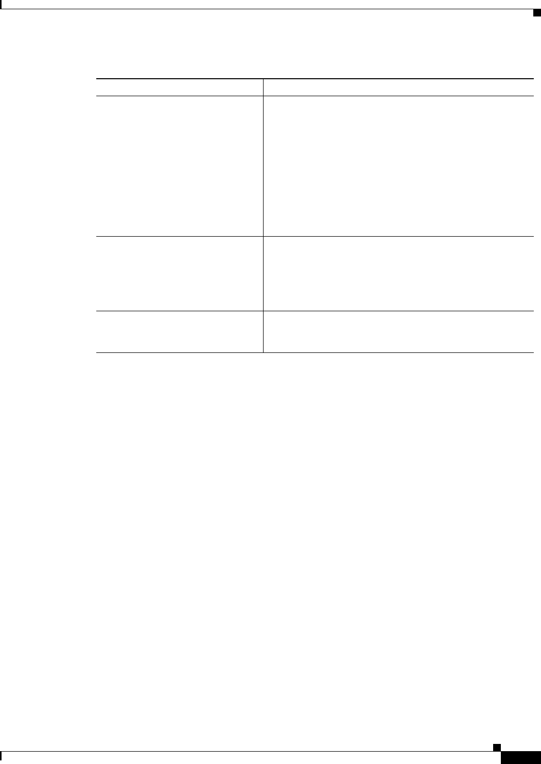
Table 1
Specification Description
EU Compliance (CE Mark) Products with CE marking indicate compliance with the Low
Voltage Directive 2006/95/EC, EMC Directive 2004/108/EC or
R&TTE Directive 1999/5/EC.
Safety UL 60950-1
CAN/CSA-C22.2 No. 60950-1
EN 60950-1
IEC 60950-1
AS/NZS 60950-1
25
Regulatory Compliance and Safety Information for the Cisco WAP571/571E Wireless Access Point (EMC Class B Devices)
78-20515-02
EMC Class B Notices and Warnings
For specific details about the years, revisions and relevant amendments please refer to the applicable
declaration of conformity available at http://www.ciscofax.com.
EMC Class B Notices and Warnings
This section includes the EMC Class B warnings for the Cisco WAP571/571E Wireless Access Point.
Class B Notice for FCC
Modifying the equipment without Cisco’s authorization may result in the equipment no longer
complying with FCC requirements for Class B digital devices. In that event, your right to use the
equipment may be limited by FCC regulations, and you may be required to correct any interference to
radio or television communications at your own expense.
This equipment has been tested and found to comply with the limits for a Class B digital device, pursuant
to Part 15 of the FCC Rules. These limits are designed to provide reasonable protection against harmful
interference in a residential installation. This equipment generates, uses and can radiate radio frequency
energy and, if not installed and used in accordance with the instructions, may cause harmful interference
to radio communications. However, there is no guarantee that interference will not occur in a particular
installation. If this equipment does cause harmful interference to radio or television reception, which can
be determined by turning the equipment off and on, the user is encouraged to try to correct the
interference by one or more of the following measures:
• Reorient or relocate the receiving antenna.
• Increase the separation between the equipment and receiver.
EMC 47CFR FCC Part 15B
Industry Canada ICES-003
EN 301 489-1, EN 301 489-17
EN 300 386
EN55022
EN55024
EN61000-3-2
EN61000-3-3
CISPR 22
CISPR 24
AS/NZS CISPR22
Radio 47CFR FCC Part 15C
Industry Canada RSS-210
EN 300 328
EN 301893
AS/NZS 4268
RF Exposure FCC OET 65, Supplement C
RSS-102
EN 50385
Table 1 (continued)
Specification Description
RSS-247

26
Regulatory Compliance and Safety Information for the Cisco WAP571/571E Wireless Access Point (EMC Class B Devices)
78-20515-02
EMC Class B Notices and Warnings
• Connect the equipment into an outlet on a circuit different from that to which the receiver is
connected.
• Consult the dealer or an experienced radio/TV technician for help.
27
Regulatory Compliance and Safety Information for the Cisco WAP571/571E Wireless Access Point (EMC Class B Devices)
78-20515-02
EMC Class B Notices and Warnings
Class B Notice for Canada
This Class B digital apparatus complies with Canadian ICES-003.
Cet appareil numérique de la classe B est conforme à la norme NMB-003 du Canada.
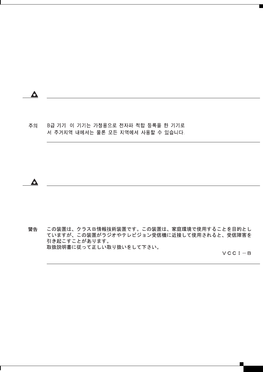
Statement 295—Class B Warning for Korea
Statement 157—VCCI Compliance for Class B Equipment
Warning
This is a Class B Device and is registered for EMC requirements for residential use. This device
can be used not only in residential areas but in all other areas.
Warning
This is a Class B product based on the standard of the VCCI Council. If this is used near a radio
or television receiver in a domestic environment, it may cause radio Interference. Install and
use the equipment according to the instruction manual.
VCCI-B
28
Regulatory Compliance and Safety Information for the Cisco WAP571/571E Wireless Access Point (EMC Class B Devices)
78-20515-02
Japanese Electric Appliance and Radio Laws
Japanese Electric Appliance and Radio Laws
Statement 571/571E—Power Cable and AC Adapter
Radio
This section describes radio compliance conditions for the Cisco WAP571/571E Wireless Access Points
EMC Class B Devices.
Caution The Part 15 radio device operates on a non-interference basis with other devices operating at this
frequency when using the integrated antennas. Any changes or modification to the product not expressly
approved by Cisco could void the user’s authority to operate this device.
Canadian Radio Warning Statement
This device complies with RSS-210 of the Industry Canada Rules. Operation is subject to the following
two conditions: (1) This device may not cause harmful interference, and (2) this device must accept any
interference received, including interference that may cause undesired operation.
Ce dispositif est conforme aÌ la norme CNR-210 d'Industrie Canada applicable aux appareils radio exempts
de licence. Son fonctionnement est sujet aux deux conditions suivantes: (1) le dispositif ne doit pas produire
de brouillage preìjudiciable, et (2) ce dispositif doit accepter tout brouillage rec?u, y compris un brouillage
susceptible de provoquer un fonctionnement indeìsirable.
Warning
When installing the product, please use the provided or designated connection cables/power
cables/AC adaptors/batteries. Using any other cables/adaptors could cause a malfunction or a
fire. Electrical Appliance and Material Safety Law prohibits the use of UL-certified cables (that
have the “UL” or “CSA” shown on the cord), not regulated with the subject law by showing
"PSE" on the cord, for any other electrical devices than products designated by CISCO.
RSS-247
CNR-247
29
Regulatory Compliance and Safety Information for the Cisco WAP571/571E Wireless Access Point (EMC Class B Devices)
78-20515-02
Radio
Guidelines for Operating Cisco WAP571/571E Wireless Access Points in
Japan
This section provides guidelines for avoiding interference when operating Cisco WAP571/571E
Wireless Access Points in Japan. These guidelines are provided in both English and Japanese.
Statement 391—Warning for Low-Power Radio Data Communications
Systems (-STD)
Warning
This equipment shares a frequency band with a wide range of equipment: e.g. industrial,
scientific, and medical equipment such as microwave ovens, premises radio stations (radio
stations requiring licenses), and specified low-power radio stations (radio stations not requiring
licenses) for RFID used for factory production lines as well as amateur radio stations (radio
stations requiring licenses).
1. Before use, confirm that no premises radio stations and specified low-power radio stations
for RFID or amateur radio stations operate in your vicinity.
2. In the event that this equipment causes harmful interference to any premises radio station
for RFID, immediately change frequencies or halt radio wave emission and contact us at the
information indicated below for consultation on interference avoidance measures (e.g.,
partition installation).
3. Contact us at the information indicated below if this equipment causes harmful interference
to any specified low-power radio stations for RFID or amateur radio stations or if other
problems arise.
Statement 391
Contact us at : http://www.cisco.com/web/JP/index.html
30
Regulatory Compliance and Safety Information for the Cisco WAP571/571E Wireless Access Point (EMC Class B Devices)
78-20515-02
Radio
Administrative Rules for Cisco Wireless Devices in Taiwan
This section provides administrative rules for operating Cisco wireless access products in Taiwan. The
rules are provided in both Chinese and English.
Wireless Devices with IEEE 802.11a/b/g Radios
Chinese Translation
English Translation
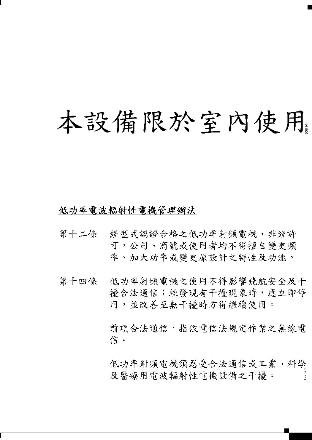
This equipment is limited for indoor use.
All Access Wireless Products
Chinese Translation

31
Regulatory Compliance and Safety Information for the Cisco WAP571/571E Wireless Access Point (EMC Class B Devices)
78-20515-02
Generic Discussion on RF Exposure
English Translation
Administrative Rules for Low-Power Radio-Frequency Devices
Article 12
For those low-power radio-frequency devices that have already received a type-approval, companies,
business units, or users should not change its frequencies, increase its power, or change its original
features and functions.
Article 14
The operation of the low-power radio-frequency devices is subject to the conditions that no harmful
interference is caused to aviation safety and authorized radio stations; and if interference is caused, the
user must stop operating the device immediately and can’t re-operate it until the harmful interference is
clear.
The authorized radio station means a radio-communication service operating in accordance with the
Communication Act.
The operation of the low-power radio-frequency devices is subject to the interference caused by the
operation of an authorized radio station, by another intentional or unintentional radiator, by industrial,
scientific and medical (ISM) equipment, or by an incidental radiator.
Generic Discussion on RF Exposure
The Cisco WAP571/571E Wireless Access Points are designed to comply with the following national
and international standards on Human Exposure to Radio Frequencies.
• US 47 Code of Federal Regulations Part 2 Subpart J
• American National Standards Institute (ANSI) / Institute of Electrical and Electronic Engineers /
IEEE C 95.1 (92)
• International Commission on Non Ionizing Radiation Protection (ICNIRP) 98
• Ministry of Health (Canada) Safety Code 6. Limits on Human Exposure to Radio Frequency Fields
in the range from 3kHz to 300 GHz
• Australia Radiation Protection Standard
To ensure compliance with various national and international Electromagnetic Field (EMF) standards,
the system should only be operated with Cisco approved antennas and accessories.
US
This system has been evaluated for RF exposure for Humans in reference to ANSI C 95.1 (American
National Standards Institute) limits. The evaluation was based on evaluation per ANI C 95.1 and FCC
OET Bulletin 65C rev 01.01. The minimum separation distance from the antenna to general bystander
is 7.9 inches (20cm) to maintain compliance.
Canada
This system has been evaluated for RF Exposure per RSS-102 and is in compliance with the limits
specified by Health Canada Safety Code 6. The system must be installed at a minimum separation
distance from the antenna to a general bystander of 7.9 inches (20cm) to maintain compliance with the
General Populace limits.
L’exposition aux radiofréquences de ce système a été évaluée selon la norme RSS-102 et est jugée
conforme aux limites établies par le Code de sécurité 6 de Santé Canada. Le système doit être installé
à une distance minimale de 7,9 pouces (20 cm) séparant l’antenne d’une personne présente en
conformité avec les limites permises d’exposition du grand public.
This equipment complies with FCC radiation exposure limits set forth for an uncontrolled environment.
This equipment should be installed and operated with minimum distance 20 cm between the radiator &
your body.
This device and it's antennas(s) must not be co-located or operating in conjunction with any other antenna
or transmitter except in accordance with FCC multi-transmitter product procedures.

32
Regulatory Compliance and Safety Information for the Cisco WAP571/571E Wireless Access Point (EMC Class B Devices)
78-20515-02
Obtaining Documentation and Submitting a Service Request
Obtaining Documentation and Submitting a Service Request
For information on obtaining documentation, submitting a service request, and gathering additional
information, see the monthly What’s New in Cisco Product Documentation, which also lists all new and
revised Cisco technical documentation, at:
http://www.cisco.com/en/US/docs/general/whatsnew/whatsnew.html
Subscribe to the What’s New in Cisco Product Documentation as a Really Simple Syndication (RSS) feed
and set content to be delivered directly to your desktop using a reader application. The RSS feeds are a free
service and Cisco currently supports RSS Version 2.0.
Cisco and the Cisco logo are trademarks or registered trademarks of Cisco and/or its affiliates in the U.S. and other countries. To view a list of
Cisco trademarks, go to this URL: www.cisco.com/go/trademarks. Third-party trademarks mentioned are the property of their respective owners. The
use of the word partner does not imply a partnership relationship between Cisco and any other company. (1110R)
© 2014 Cisco Systems, Inc. All rights reserved.
EU
This system has been evaluated for RF exposure for Humans in reference to the ICNIRP (International
Commission on Non-Ionizing Radiation Protection) limits. The evaluation was based on the EN 50385
Product Standard to Demonstrate Compliance of Radio Base stations and Fixed Terminals for Wireless
Telecommunications Systems with basic restrictions or reference levels related to Human Exposure to
Radio Frequency Electromagnetic Fields from 300 MHz to 40 GHz. The minimum separation distance
from the antenna to general bystander is 20cm (7.9 inches).
Australia
This system has been evaluated for RF exposure for Humans as referenced in the Australian Radiation
Protection standard and has been evaluated to the ICNIRP (International Commission on Non-Ionizing
Radiation Protection)limits. The minimum separation distance from the antenna to general bystander
is 20cm (7.9 inches).
Generic Statements - for other countries
ANSI C 95.1 (99)
This system has been evaluated for RF exposure for Humans in reference to the ANSI (American
National Standards Institute)limits as referenced in C 95.1 (99). The minimum separation distance
from the antenna to the user is 7.9 inches (20cm).
ICNIRP Limits
This system has been evaluated for RF exposure for Humans in reference to the ICNIRP (International
Commission on Non-Ionizing Radiation Protection) limits. The minimum separation distance from the
antenna to the user is 20cm (7.9 inches).