PERVASIVE DISPLAYS SW074AZ1D2 Eco-Sign 7.4" Device User Manual
PERVASIVE DISPLAYS INC. Eco-Sign 7.4" Device Users Manual
Users Manual

i
ECO-Sign
User Manual
Rev. 1.0
July, 2011
Pervasive Displays Inc.
Tel:+886-6-2795399 | Fax:+886-6-2795300

ii
Contents
I. Introduction ............................................................................................ 1
1. What is the ECO-Sign Solution? ......................................................... 1
2. ZigBee Wireless Technology ............................................................... 2
3. ZigBee Topologies ............................................................................ 3
4. Node Types ..................................................................................... 4
5. ECO-Sign Model & Composed of Elements ........................................... 5
II. Pre-Installation ....................................................................................... 7
III. Quick Start with ECO-Sign ........................................................................ 8
IV. Quick Start with Template Design ............................................................ 10
V. Software Installation .............................................................................. 11
1. Supported Operating Systems.......................................................... 11
2. Instructions ................................................................................... 11
VI. Hardware Installation ............................................................................. 12
1. Overview ....................................................................................... 12
2. Mounting ECO-Sign ........................................................................ 13
3. LED Indicator (on Device) ............................................................... 18
4. Connecting Coordinator / Router ...................................................... 18
5. Recharging Device .......................................................................... 19
VII. Coordinator Network Configuration .......................................................... 20
1. Communication Port ....................................................................... 20
2. Configure Coordinator ..................................................................... 21
3. Web Configuration .......................................................................... 23
VIII. Working with Device and Coordinator ....................................................... 26
1. Starting ESS (ECO-Sign System) ...................................................... 26
2. Coordinator ................................................................................... 27
3. Target ........................................................................................... 29
4. EPD Device .................................................................................... 31
5. Template ....................................................................................... 35
6. Schedule ....................................................................................... 40
7. Configuration ................................................................................. 41

iii
8. How does Eco-Sign work? ............................................................... 43
9. Information ................................................................................... 44
IX. How to update firmware? ....................................................................... 46
1. Naming rule .................................................................................. 46
2. Update tool ................................................................................... 46

User Manual of ECO-Sign v1.0
-1-
Confidential
I. Introduction
1. What is the ECO-Sign Solution?
The ECO-Sign solution is a green, eco-friendly and low power signage solution which
includes e-Paper devices with ZigBee wireless gateways and software.
The ECO-Sign has ultra-low power consumption and provides wireless updates of the
display. With no wires and rechargeable batteries the ECO-Sign is easy to install and is a
perfect solution for office or factory automation, electronic shelf labels, e-Signage/e-POP,
logistic or container applications.
The included software has a powerful template designer and the built in scheduler
provides an easy remote management tool. The solution is characterized by the following
features:
(1) Slim & Light: Fewer parts, simple electronics, no thermal concerns and less
mechanical challenges.
(2) Active Matrix TFT: Built in active-matrix electrophoretic display.
(3) Paper Like: It is reflective, has a very wide viewing angle and excellent contrast.
(4) Rechargeable Battery: 1 year operating time on a single charge.
(5) Wireless: Without any power cord and network cables, the content can be updated
wirelessly and controlled remotely.
(6) Ultra Low Power Consumption: It is very energy efficient and allows you to
define when the device sleeps or wakes up.
(7) Color: It also provides area color for color requirements.
(8) Secure: No OS, so impervious to hacker & virus. 128 bits AES (16 Bytes) security.
(9) Lower Content Cost: Simple and straightforward. No need for computing power or
memory overhead.
(10) Low Maintenance: Light and Thin, easy to install and repair, less installation
overhead.
User Manual of ECO-Sign v1.0
-2-
Confidential
2. ZigBee Wireless Technology
ZigBee is a specification for a suite of high level communication protocols using small,
low-power digital radios based on the IEEE 802.15.4 standard for Wireless Personal Area
Networks (WPANs). The technology defined by the ZigBee specification is intended to be
simpler and less expensive than other WPANs, such as Bluetooth. ZigBee is targeted at
radio-frequency (RF) applications that require a low data rate, long battery life, and
secure networking and is designed for wireless controls and sensors.
ZigBee has two modes of operation: Active, also called WakeUp, and Sleep mode. In the
active mode the device is communicating with other nodes in the network. In sleep mode
the radio is turned off and the system enters power saving mode. The user can configure
the interval of both states.
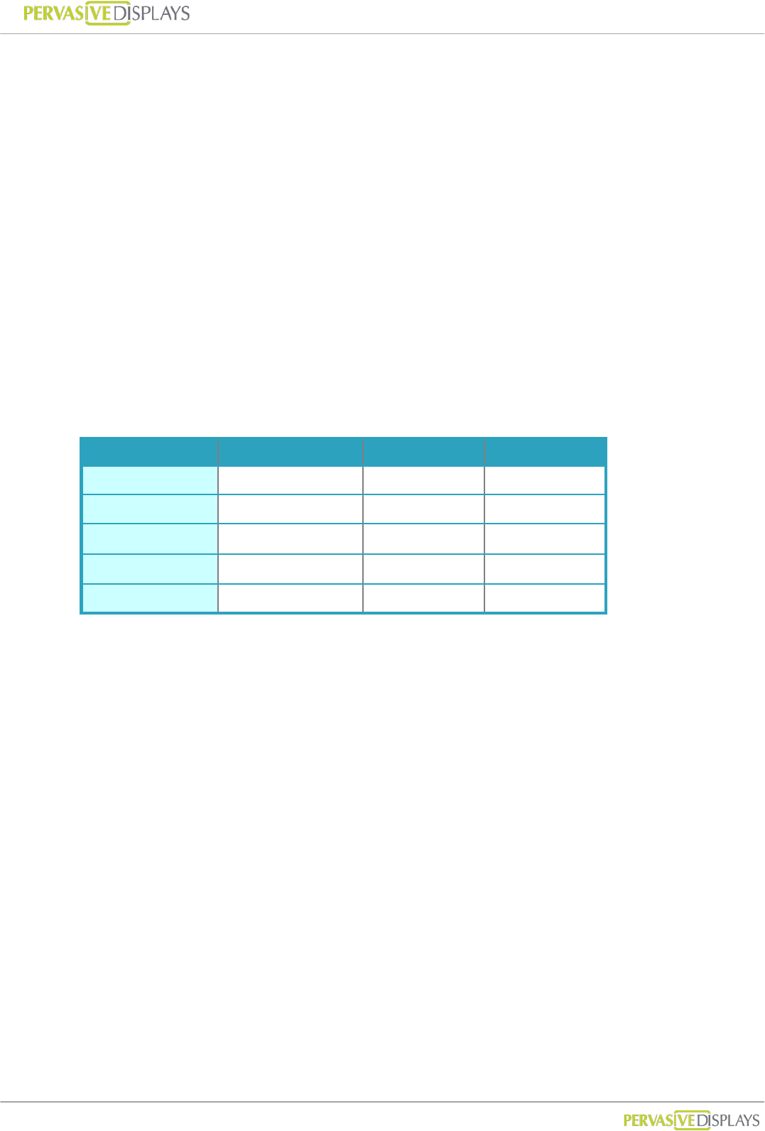
ZigBee operates in the industrial, scientific and medical (ISM) radio bands; 868 MHz in
Europe, 915 MHz in the USA and Australia, and 2.4 GHz in most jurisdictions worldwide.
2.4GHz 868MHz 915MHz
Band ISM ISM
Coverage Worldwide Europe US
Modulation QPSK BPSK BPSK
Channel 16 1 10
Data Rate 250K bps 20K bps 40K bps
The ECO-Sign uses ZigBee 2.4GHz.
User Manual of ECO-Sign v1.0
-3-
Confidential
3. ZigBee Topologies
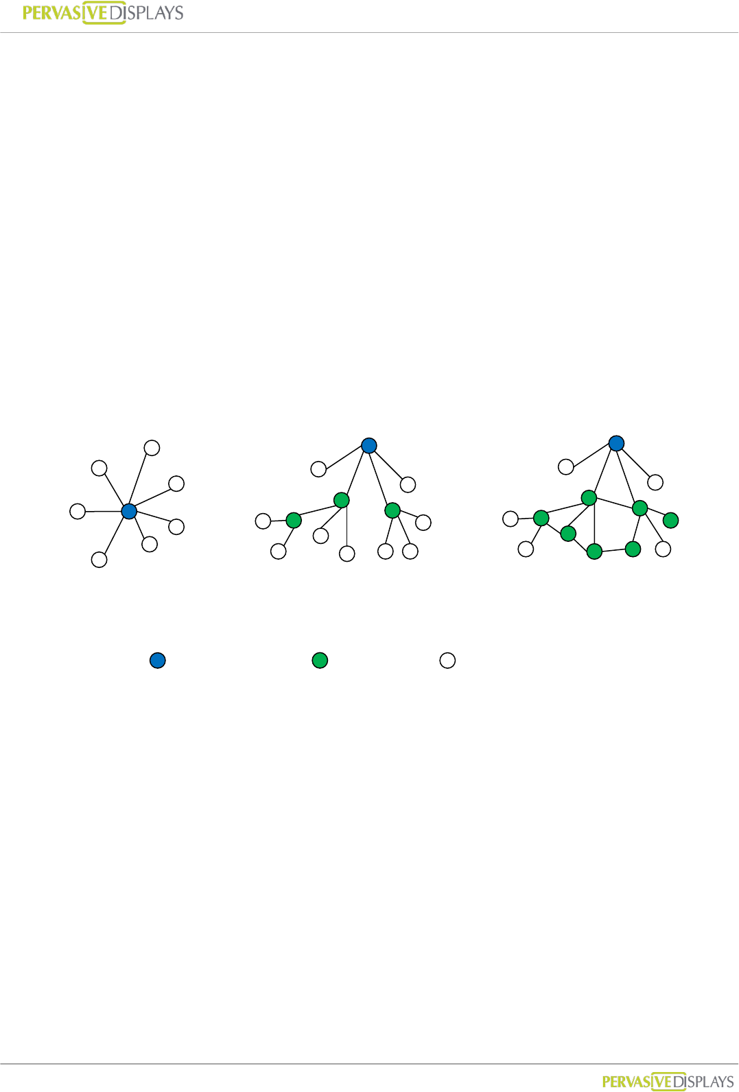
A ZigBee network can adopt one of three topologies: Star, Tree or Mesh.
(1) Star Topology
A Star network has a central node, which is linked to all other nodes in the network.
All messages travel via the central node.
(2) Tree Topology
A Tree network has a top node with a branch/leaf structure below. To reach its
destination, a message travels up the tree (as far as necessary) and then down the
tree.
(3) Mesh Topology
A Mesh network has a tree-like structure in which some leaves are directly linked.
Messages can travel across the tree, when a suitable route is available.
Star
Tree
Mesh
: Coordinator
: Router
: End-Device

User Manual of ECO-Sign v1.0
-4-
Confidential
4. Node Types
The ZigBee standard has the capacity to address up to 65,535 nodes in a single network.
There are three different types of nodes in a ZigBee network:
(1) ZigBee Coordinator: The most capable device, the coordinator forms the root of the
network tree and might bridge to other networks. It is the device that started the
network originally and is able to store information about the network, including acting
as the Trust Center & repository for security keys. In the above illustration the ZigBee
Coordinator is color-coded in blue.
(2) ZigBee Router: As well as running an application function, a router can act as an
intermediate node, passing messages from source to destination. ZigBee Routers are
color coded in green.
(3) ZigBee End Device: It’s equal to our ECO-Sign Device. ECO-Sign Device contains
just enough functionality to talk to the parent node (either the Coordinator or a Router)
and refresh the content on e-Paper display. ZigBee End Devices are color-coded in
white.
User Manual of ECO-Sign v1.0
-5-
Confidential
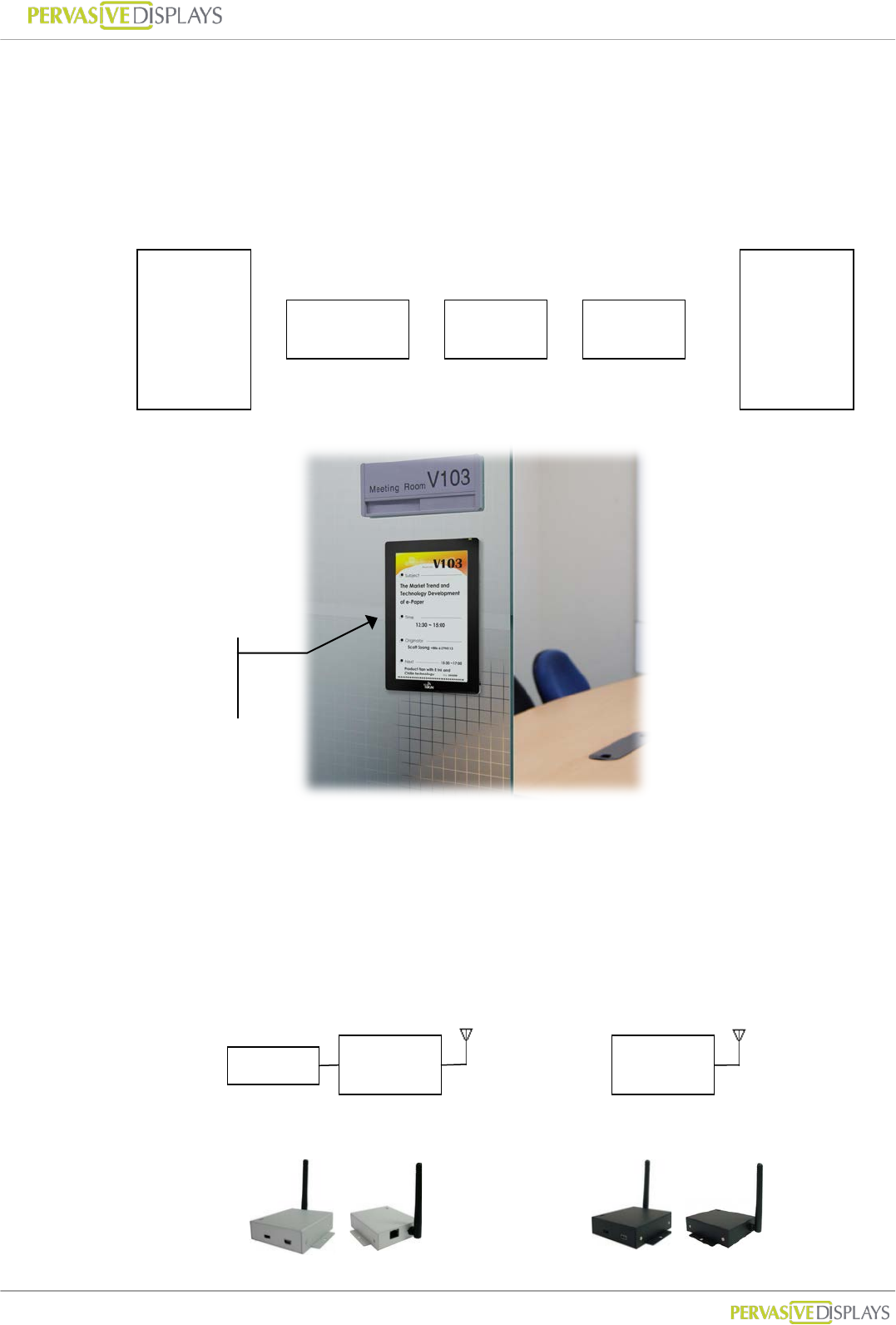
5. ECO-Sign Model & Composed of Elements
The components of the ECO-Sign solution are illustrated below:
(1) ECO-Sign Devices: (hereinafter the “Device”) The Active-Matrix e-Paper display with
Timing Control board, ZigBee module and rechargeable battery.
(2) Gateways: Gateways include ZigBee Coordinator and ZigBee Router. ZigBee
Coordinator (hereinafter the “Coordinator”) is the beginning of ZigBee network tree
and is capable to transfer data from Ethernet to ZigBee signal which is addressable by
internet/intranet IP.
Router (hereinafter the “Router”) acts as repeater to enhance the ZigBee signal hence
increasing the distance a node can be installed from the coordinator.
e-Paper
Display
Timing
Controller
ZigBee Battery
+
+
+
=
ECO-Sign
Device
ZigBee ZigBee
Ethernet
Coordinator
Router
ECO-Sign
Device
User Manual of ECO-Sign v1.0
-6-
Confidential
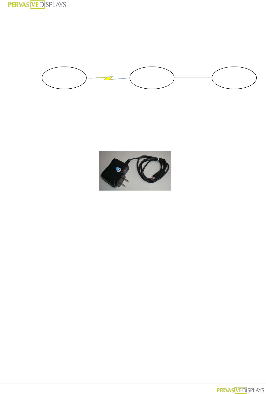
(3) Software: This software is the graphic user interface to manage devices, gateways,
networks, data sources, schedules and templates.
(4) Peripherals: mini-USB power adapter.
Coordinator and Router are powered by this mini-USB power adapter.
Device is powered by rechargeable battery which has embedded in the cover. The
adapter can also be used for recharging the Devices.
ECO-Sign
Devices
Gateways Software
ZigBee/RF
TCP/IP
Coordinator
Router

User Manual of ECO-Sign v1.0
-7-
Confidential
II. Pre-Installation
(1) Please remember to switch the Devices OFF after testing or demonstrating in order to
save battery power.
(2) If you purchase 2 sample kits or more, different color labels (dot sticker) on the
devices will identify the components of respective kit. Note that a different color also
indicates a different ZigBee channel. There will be no interaction by between the
channels, hence a coordinator can only communicate with the same color coded
routers and ECO-Signs. Please make sure that all the devices (Coordinator, Router and
ECO-Sign) have the same color label.
(3) This software is only used for ZigBee Coordinator with Ethernet (RJ45 port) which
firmware version is greater than 0.53. It doesn’t work for Coordinator connecting with
computer by USB cable or firmware version is less than 0.5.
User Manual of ECO-Sign v1.0
-8-
Confidential
III. Quick Start with ECO-Sign
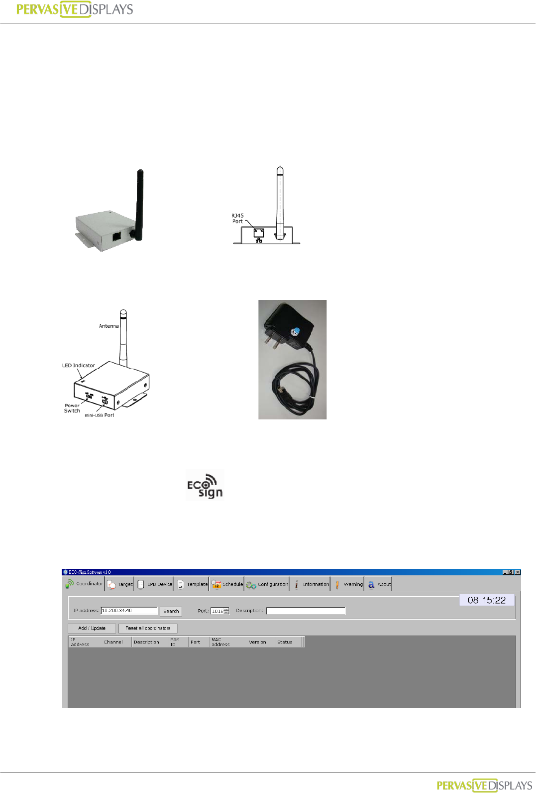
(1) Connect the Coordinator:
(a) Plug an Ethernet cable into the RJ45 connector and your network switch.
An address will automatically be assigned by DHCP.
Coordinator
(b) Plug in the mini USB power adapter and flip the power switch on the Coordinator.
Coordinator. mini USB power adapter
(2) Install the software:
Double click ESS_v1.0.exe software and follow the one screen instructions.
Execute ECOSign.exe
(3) Find the Coordinator:
Click Search on the Coordinator tab.
Click the select check box and the select button.
User Manual of ECO-Sign v1.0
-9-
Confidential
(4) Activate the ECO-Sign:
(a) Flip the power switch on the ECO-Sign and copy the discovered MAC address on
the EPD Device tab.
(b) Select the size and target template. Click [Add/Update] to link the Device and wait
for Device to update.
User Manual of ECO-Sign v1.0
-10-
Confidential
IV. Quick Start with Template Design
(1) Creating Templates:
Creating a template is easy. Simple click the “New Template” radio button.
Name the Template and select the size and the orientation from the drop down menus.
Click [Next] to go to the drawing board to insert objects.
(2) Configuring a Data Source:
(a) In this example we configure the ECO-sign software to use Microsoft Access.
Click the “Microsoft Access” and open the file browser by clicking the […] button.
Browse to the location of mdb file and click “Test” to establish the connection.
(b) Select the desired table from the drop down list. Database entries can now be
inserted by clicking the Database icon on the drawing board.
(c) Note: It’s only possible to have one database connection. The configuration
connection applies to all Templates.
(3) Using the Drawing board
Insert objects by clicking
the appropriate icon.
Move objects to the
desired position on the
drawing board with your
mouse.
Use your mouse to resize
the objects.
Object attributes are
described here e.g. size
and resolution.
Object properties are shown here.
Browse image file path. Insert text
and change the font type with a
few clicks. Show barcode by given
text and numbers.

User Manual of ECO-Sign v1.0
-11-
Confidential
V. Software Installation
1. Supported Operating Systems
Microsoft Windows XP / Vista / 7 : 32 bits or 64 bits
2. Instructions
Software name : ECO-Sign System (ESS)
Double click the installer to setup system in your computer.
Please follow the guide of the installer on screen.
User Manual of ECO-Sign v1.0
-12-
Confidential
VI. Hardware Installation
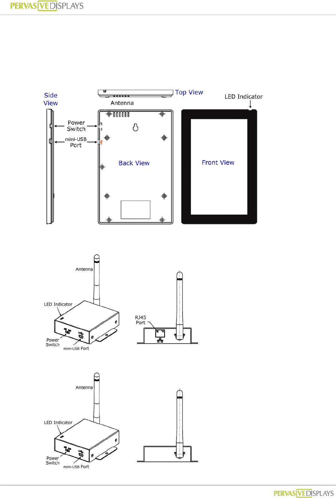
1. Overview
(1) ECO-Sign Device
(2) Coordinator
(3) Router
User Manual of ECO-Sign v1.0
-13-
Confidential
2. Mounting ECO-Sign
ECO-Sign Device
There are two available mounting kits for the ECO-Sign.
1. Wall mounting kit
2. Table stand
Both mounting kits are optional and available for ordering.
Wall mounting
The wall mounting kit includes:
(a) 1 wall-mount bracket with 4 screws
(b) 1 device-mount bracket with 4 screws
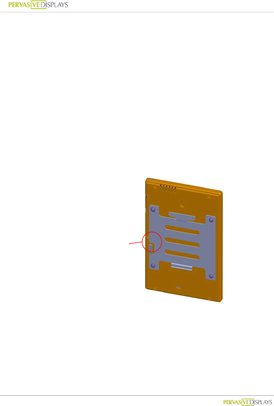
Attaching the Device bracket
(a) Slowly screw the four device screws into Device’s rear cover holes.
Make sure that the lock is at the left side as indicated on the picture
below.
Check the lock is
at left side.
User Manual of ECO-Sign v1.0
-14-
Confidential
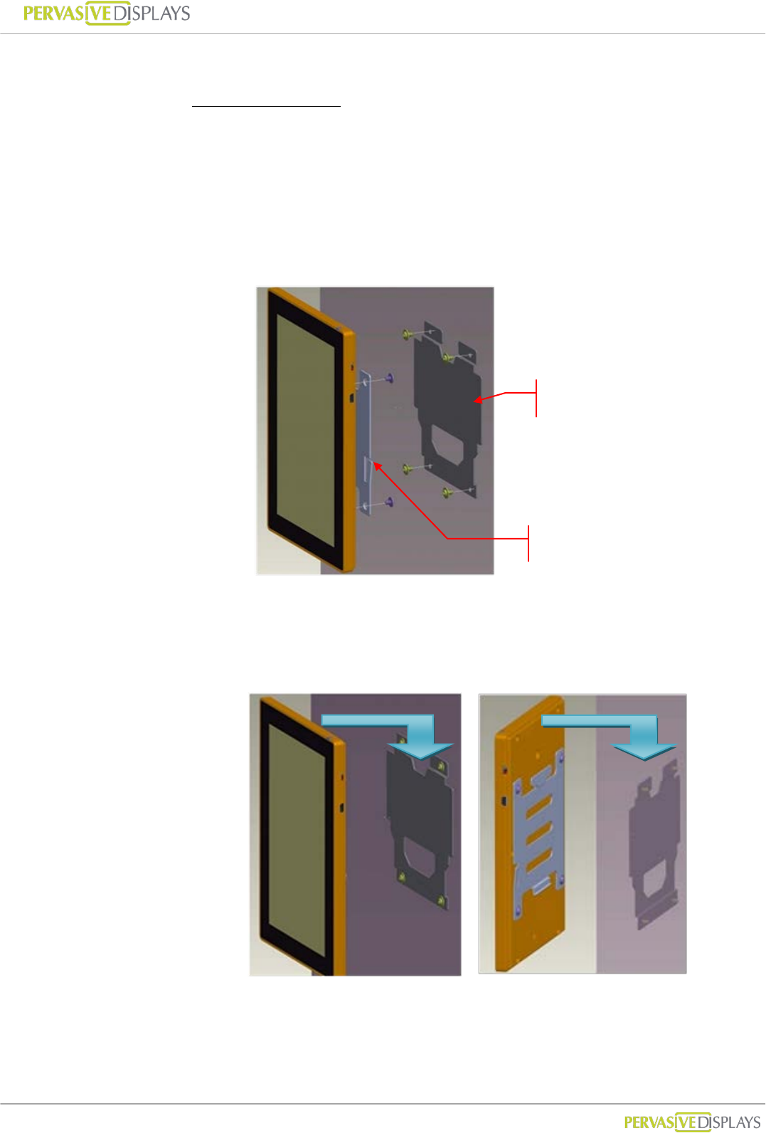
Steps to mount ECO-Sign Device
Portrait orientation
(a) Find an appropriate place to mount the Device.
(b) Mark the locations of the four screws using the wall-mount bracket
as a template. You can also fasten the four provided wall screws
directly to align the mounting bracket. Notice the orientation of
the wall bracket in the picture below.
(c) Attach the Device to the wall-mount.
Align the hinges and slide the Device down to the lock on the left side
makes a click sound.
Front view
Rear view
Wall-mount bracket
Device-mount bracket
User Manual of ECO-Sign v1.0
-15-
Confidential
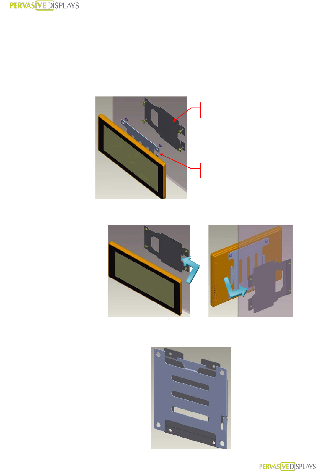
Landscape orientation
(a) Find an appropriate place to mount Device.
(b) Mark the locations of the four screws using the wall-mount bracket
as a template. You can also fasten the four provided wall screws
directly to align the mounting bracket. Notice the orientation of
the wall bracket in the picture below.
(c) Attach Device to wall-mount bracket from right side.
This diagram shows both brackets mounted type.
Front view
Rear view
Wall-mount bracket
Device-mount bracket

User Manual of ECO-Sign v1.0
-16-
Confidential
Steps to detach ECO-Sign Device
(a) If you want to detach the Device, you need a flat screwdriver to
release the lock at wall-mount bracket.
(b) Press down the lock and slide the sign in the direction of the power
switch.
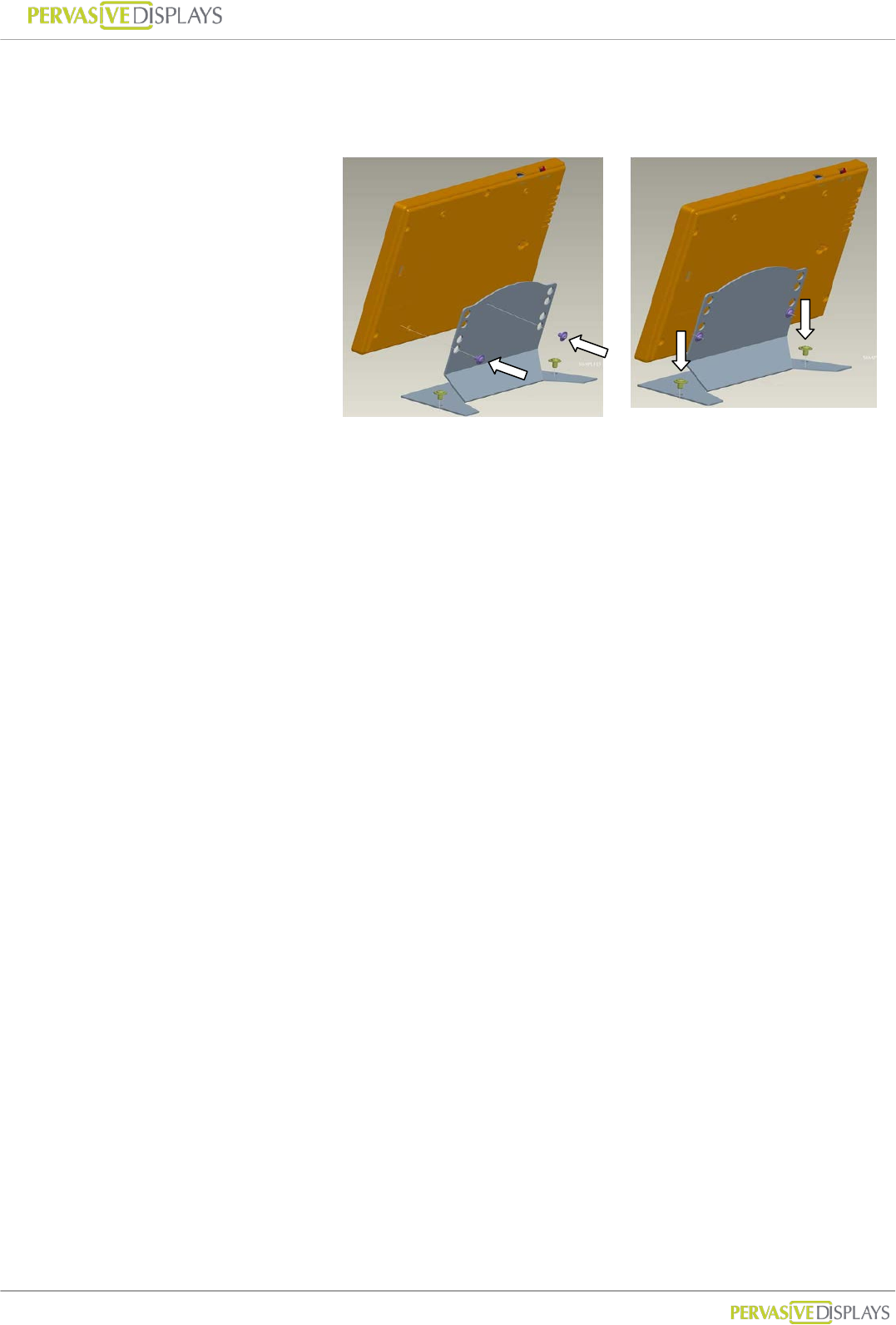
Table Stand
The table stand includes
(a) 1 device-mount stand with 4 screws
Device-mount bracket
(a) Slowly screw the two device screws into Device’s rear cover holes with
stand kit.
(b) Secure the stand to the table.
- Portrait orientation
(a)
(b)
(a)Unlock
(b)Detach
User Manual of ECO-Sign v1.0
-17-
Confidential
- Landscape orientation
(a)
(b)
User Manual of ECO-Sign v1.0
-18-
Confidential
3. LED Indicator (on Device)
The LED indicator has two color types on the front cover top of the Device.
(1) G
Gr
re
ee
en
n: When the Device is receiving or transmitting signal, the Green LED will be
flashing.
(2) O
Or
ra
an
ng
ge
e: When you use USB cable or power adapter to recharge the battery of the
Device, the orange LED will light up. When fully charged the LED will turn off.
It typically takes 6-8 hours to fully charge the battery.
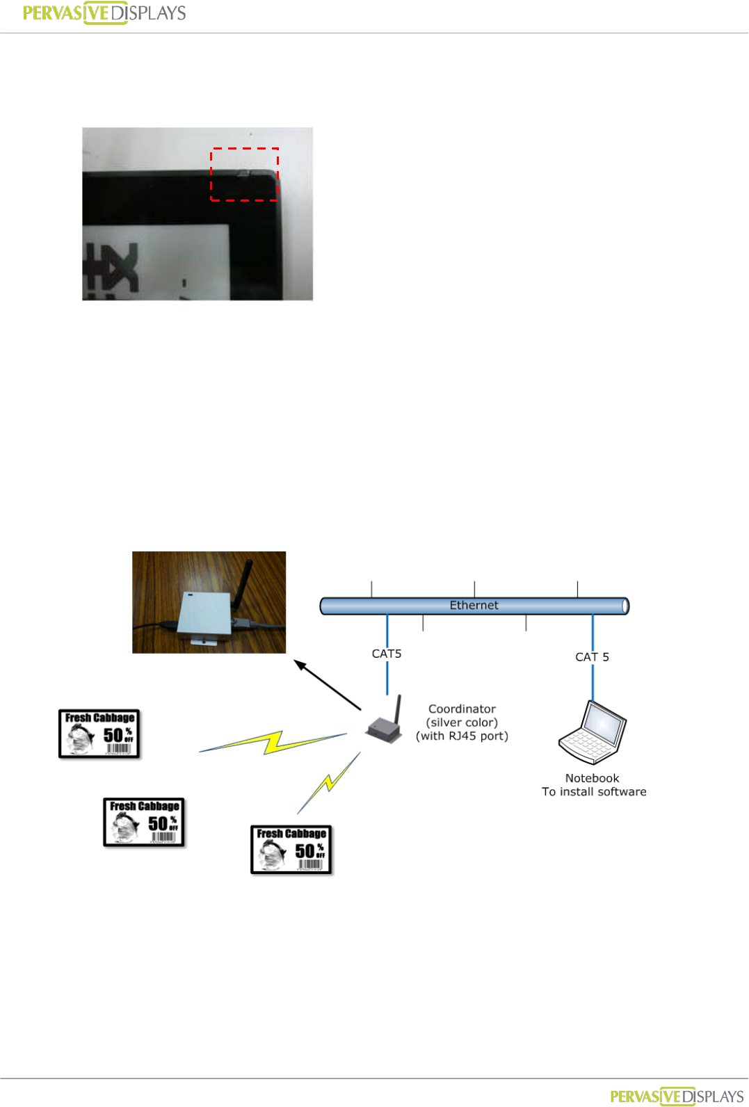
4. Connecting Coordinator / Router
The coordinator connects to the LAN with a regular network cable to control and
communicate with nodes in the ZigBee network. The typical layout is shown below.
(1) Computer: Please prepare a standalone computer or server to install software and
connect to local network in order to search Coordinator and control Devices later.
(2) Ethernet: Please make sure your intranet has a DHCP server and allows Coordinator
to request a private IP in network.

User Manual of ECO-Sign v1.0
-19-
Confidential
(3) Coordinator: Please use CAT5 cable to connect with Coordinator to the local network
and power it by the provided mini-USB power adapter. If you order two or more
Coordinators, different color labels are pasted on each Coordinator indicating
different ZigBee channels.
(4) Router: Please power the router by the provided mini-USB power adapter.
(5) The devices are now ready to use and should be placed in an area covered by the
ZigBee network.
5. Recharging Device
The Device will arrive with full battery capacity; you will not need to charge it prior to
first use.
If the display of the Device is unable to display the selected content correctly, or if the
LEDs do not light up anymore, the Device may be out of power.
To recharge the battery of the Device, connect the mini-USB head of the USB adapter
to the mini-USB port of the Device, or connect the USB head to either a USB charger
or a USB port on your computer by USB cable.
The USB power adapter works with the Device, Router and Coordinator.
User Manual of ECO-Sign v1.0
-20-
Confidential
VII. Coordinator Network Configuration
There are two networks built in ZigBee Coordinator, which are Ethernet network
(IEEE802.3) and ZigBee wireless network (IEEE802.15.4).
This section will guide you how to configure Ethernet network includes where to change
Ethernet port number communicating with Coordinator by a web user interface.
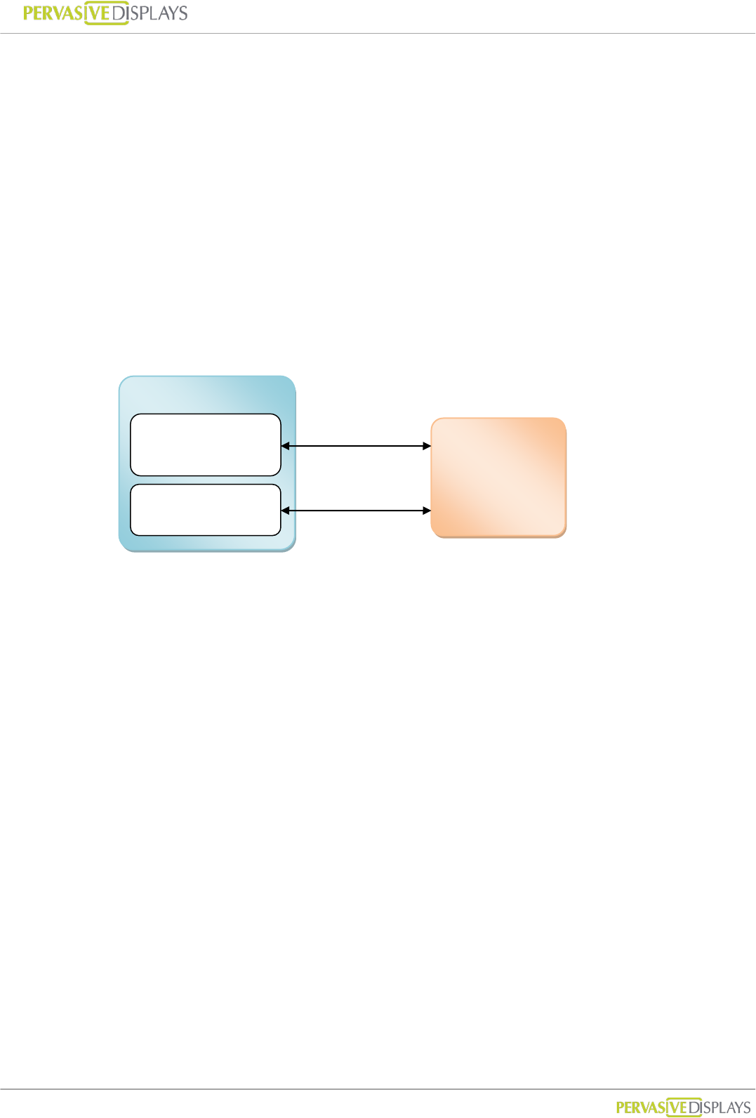
1. Communication Port
The communication between Coordinator and ECO-Sign System is working by Ethernet
protocol. You will find below diagram shows the model and ports:
Coordinator is a gateway with RJ45 port to transfer data from Ethernet to ZigBee wireless
signal. We use default port number 23 /TCP to communicate with Coordinator. This
communication port can be changed by web configuration to suit your network security
policy.
In the following introduction, you will know how to find a Coordinator adding in ECO-Sign
System in order to control Devices. The default port number 1001 is fixed. If you want to
use this function to find a Coordinator in your network, you should add this policy allowing
port number 1001 and UDP type from IP address binding with the computer that ECO-Sign
System installed to IP address of Coordinator got. If your network security is disallowed to
add this policy, you need to find out what IP address that Coordinator got by your firewall
system or device, and directly type the IP address and port number of the Coordinator to
add it on.
ECO-Sign System
Communication
Coordinator
Finder
Coordinator
Port 23/TCP
Port 1001/UDP
User Manual of ECO-Sign v1.0
-21-
Confidential
2. Configure Coordinator
(1) Factory defaults
Item Value
Link in IP Address http://192.168.1.1
User name and Password Username : admin
Password : admin
Server Name PDI ZigBee Mode
Address Type Static IP
Static Address 192.168.1.1
Subnet Mask 255.255.255.0
Default Gateway 192.168.1.1
Communication Port 23
If you purchase our demo kit, we will preset the Address Type to DHCP/Auto IP.
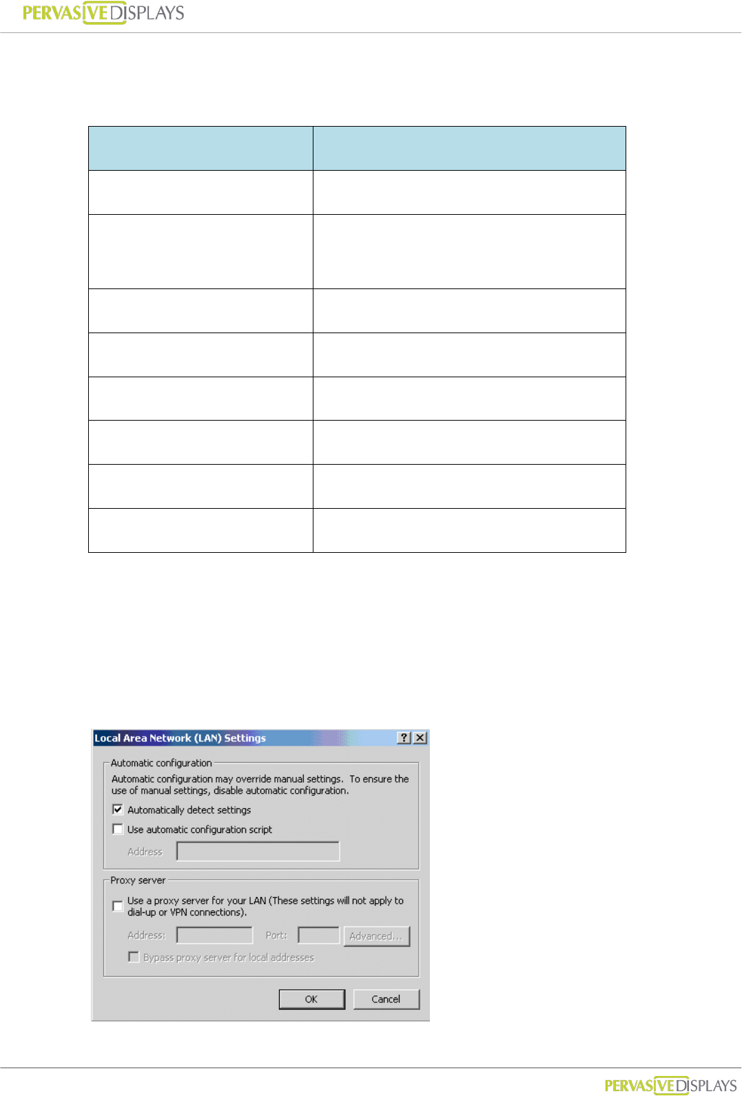
(2) Connect with Coordinator
Before you are doing the following steps, please remove your proxy setting in
advance.
User Manual of ECO-Sign v1.0
-22-
Confidential
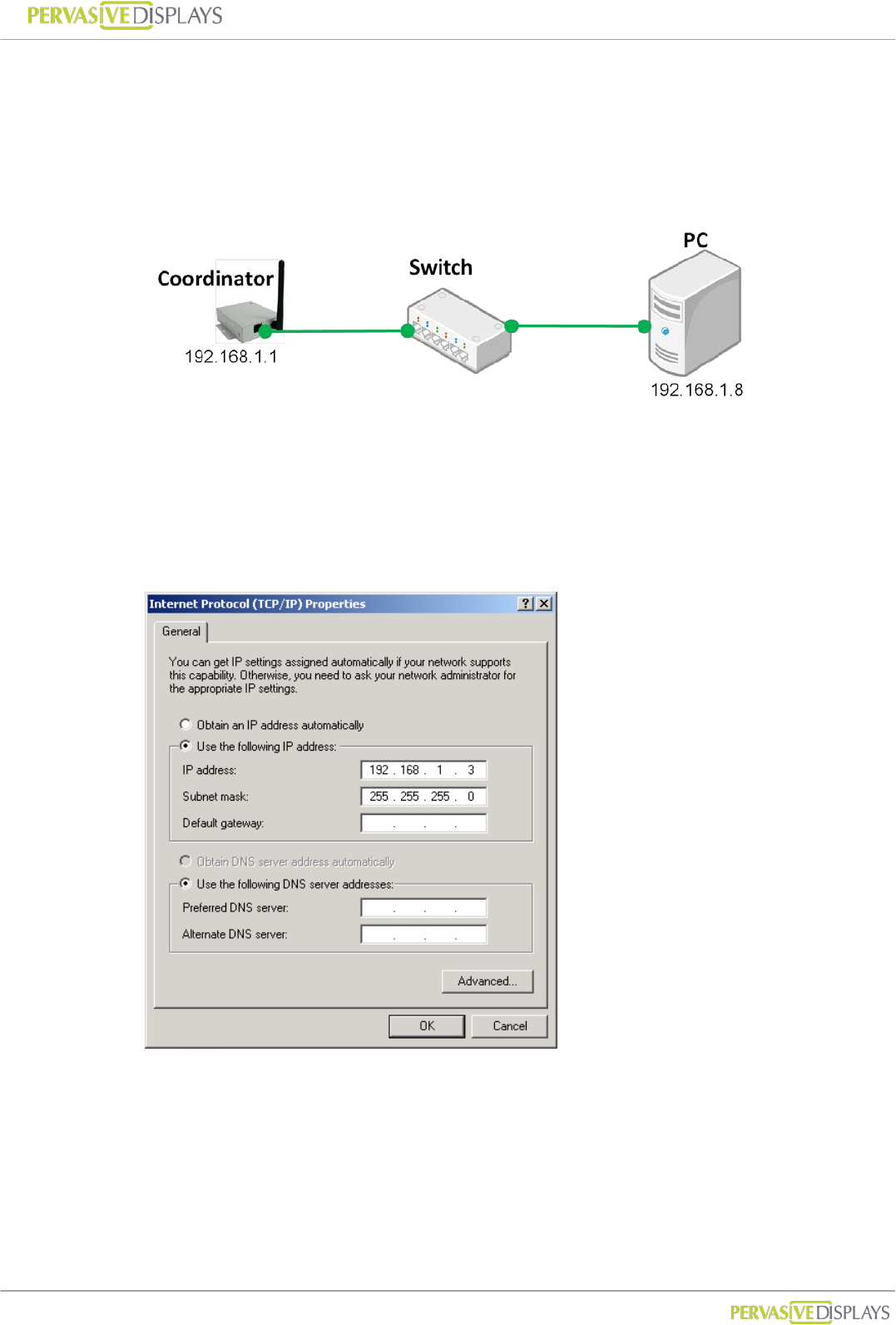
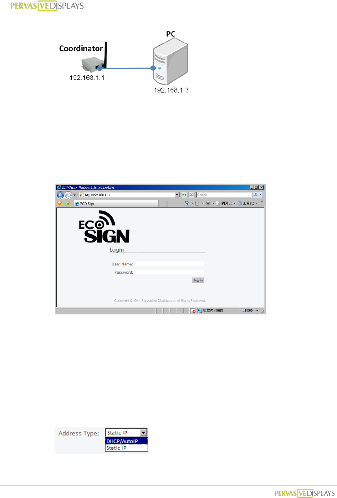
(a) Over Ethernet
You can use intranet network or build a sub network using switch to connect with
Coordinator. Note that your network segment should the same as Coordinator
that IP address beginning of “192.168.1.x”. For example:
(b) Crossover cable
Note that your network segment should the same as Coordinator that IP address
beginning of “192.168.1.x”. You can change your internet protocol (TCP/IP)
properties likes below:
Please use a crossover network cable to connect with Coordinator and computer.
User Manual of ECO-Sign v1.0
-23-
Confidential
3. Web Configuration
(1) Login
(a) Open your browser. Input URL for “http://192.168.1.1”.
(b) You will see this web page for login. Please input user name and password.
If you login success, you will find a page to show status and configuration.
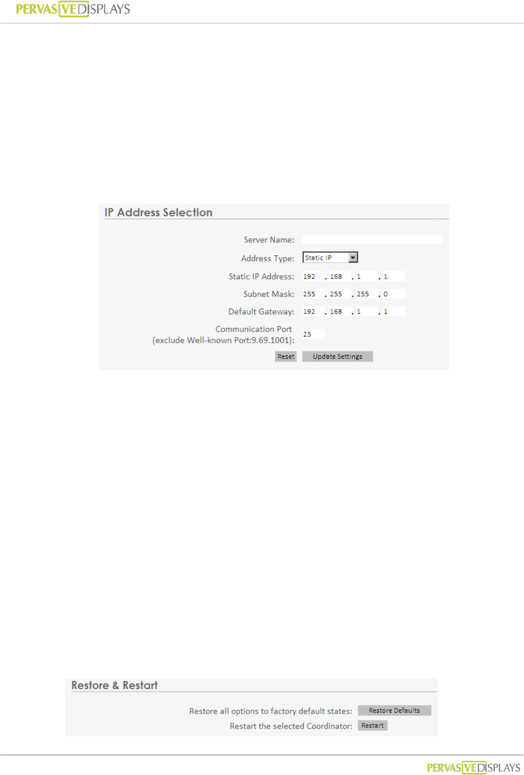
(2) Configuration
(a) Server Name:
You can define a Coordinator name here. When you add a Coordinator to
ECO-Sign System, this name will be showed in the list which helps you to clear
indentify it, so please name it meaningful. Maximum length is 32 characters.
(b) Address Type:
User Manual of ECO-Sign v1.0
-24-
Confidential
DHCP/Auto IP:
The IP address, Subnet mask and gateway of Coordinator will be assigned by
DHCP server in the network. We suggest you to select this address type for
easier configuring Coordinator in your network.
Static IP:
The IP address, Subnet mask and gateway of Coordinator have to be assigned
by network or system administrator.
(c) Communication Port:
This port is used for communicating with Coordinator. For general network, you
don’t need to change this port number. If your company has firewall or security
policy to deny any protocols and ports, you should add a policy to allow this port
number, TCP type and IP address from Coordinator to the computer that installs
ECO-Sign system. If this port number 23 conflicts your security policy, you can
change this number to other one here.
(d) Reset:
This button to clear the value in fields above.
(e) Update Settings:
Once you press this button, all of the settings will be updated to Coordinator. You
may lose the connection with Coordinator. Please kindly use the new setting to
login again to make sure you get the correct configuration.
(3) Restore and Restart
User Manual of ECO-Sign v1.0
-25-
Confidential
(a) Restore Defaults:
Press this button will restore all options to factory defaults. Note that the Address
Type will be reset to “DHCP/Auto IP”.
(b) Restart:
Press this button to restart this Coordinator.
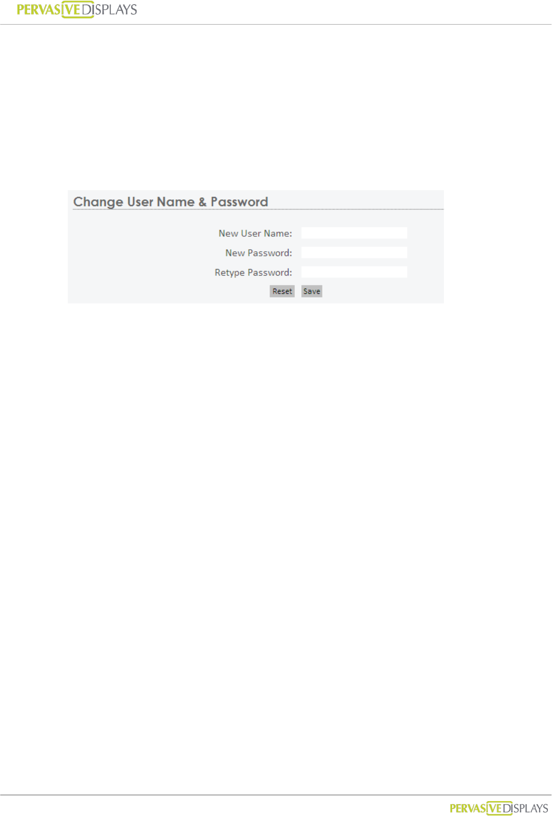
(4) Change User Name and Password
If this is your first time to login Coordinator web configuration, you should change the
user name and password here.

User Manual of ECO-Sign v1.0
-26-
Confidential
VIII. Working with Device and Coordinator
1. Starting ESS (ECO-Sign System)
(1) ECO-Sign System provides full access all the functionality of ECO-Sign solution
without any activation or registration.
(2) Execute ECOSign.exe
(3) There are several tab strips on the form:
Tab Descriptions
Coordinator This page allows user to manage the list of Coordinator. When an
additional Coordinator is added in the network, use this page to
find it.
Target Target is an object that EPD Device serves. On this page, the user
can change template and schedule.
EPD Device This page allows the user to manage the list of Devices. In this
page, user can change the device’s size, assign target objects and
clear know device information.
Template The template tab allows user to manage the list of templates.
Design new layouts, place text and image, link with data sources,
connect Microsoft outlook and show barcode etc.
Schedule The schedule page provides recurring and unconventional time
intervals to configure the device active or sleep modes.
Configuration Some system parameters of ESS.
Information A text box to show logging information and events in the system.
Warning The page shows warnings which need user to pay attention.
User Manual of ECO-Sign v1.0
-27-
Confidential
2. Coordinator
After attaching a Coordinator to network, you have to register it in the list.
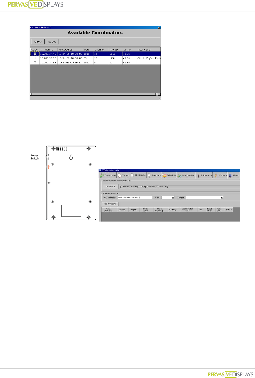
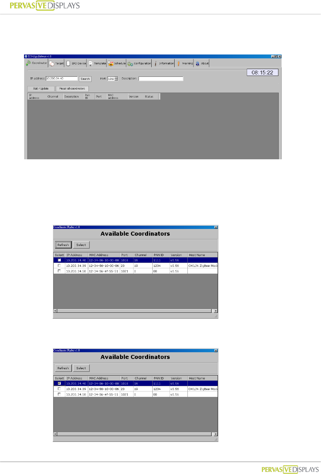
To add a new Coordinator:
(1) Click [Search] button. A new window “Coordinator Finder” will pop up. If the new
Coordinator has joined the network correctly, it appears on the list, otherwise,
please click [Refresh] button to search for it again or check the network cable of
Coordinator.
(2) Select the Check Box of each Coordinator which you want to add in the list for
managing. Click [Select] button to exit the window.
User Manual of ECO-Sign v1.0
-28-
Confidential
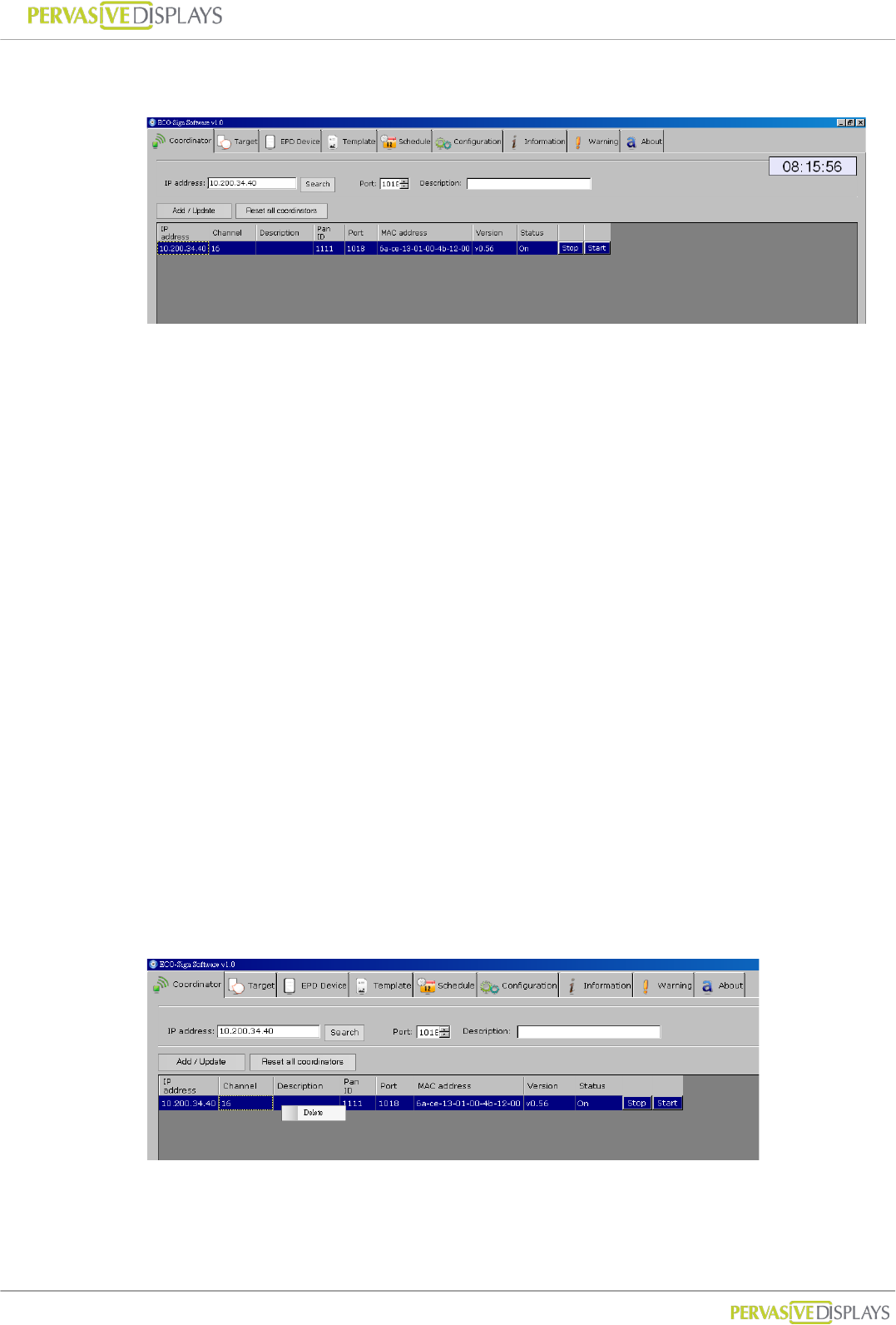
(3) The new Coordinator will be listed on the grid. Please verify that the “Status” of
the coordinator is “On”.
(4) If you want to manual add a Coordinator, you can directly type the IP address of
the Coordinator, the port number and the description. The default port number is
23 /TCP. How to change this port number, please find page.20 “VII.Configure
Network Configuration”.
To edit Coordinator:
(1) The “Channel” and “Pan ID” are set to their default values in production. A
firmware update is required to change the settings. The information will be
updated automatically while Coordinator is working.
(2) Click a list that you would like to edit. All of the data will be shown on the top
fields.
(3) It is not possible to change the IP address in the software. If you want to change
the IP address contact your network administrator.
(4) Press [Add/Update] button to finish editing data.
To delete Coordinator:
(1) Right click mouse button on a list that you would like to remove, press [Delete] to
remove it.
User Manual of ECO-Sign v1.0
-29-
Confidential
3. Target
Target is an object that EPD Device can serve. A target name should be easy to understand
with a meaningful name and description. For example, if you want to define a target for
conference room M203 located in factory 2, building A on the 2nd floor, you could give the
target name for “F2BAM203”. In the description field you can use “Factory 2, Building A,
2nd Floor, M203 meeting room”.
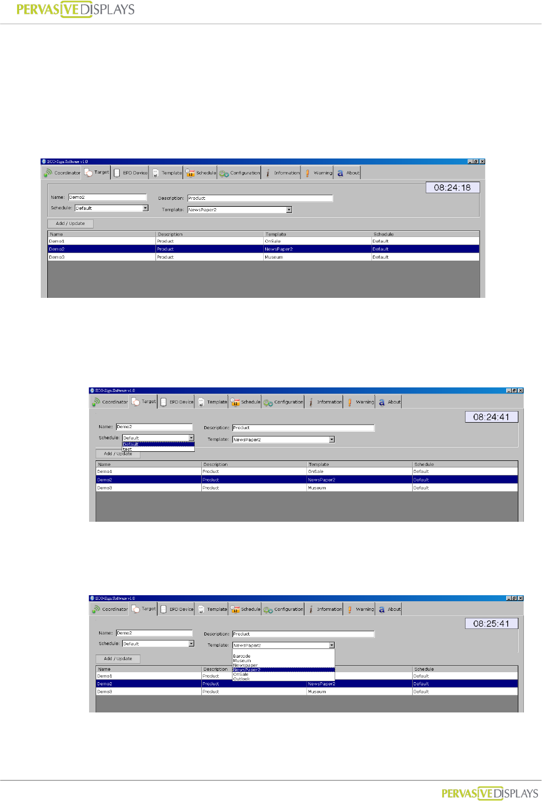
To add a new Target:
(1) Input a meaningful name and detail description of a new Target.
(2) If you have not yet defined new schedule, you can select “Default” Schedule first.
(3) Assign a Template to the Target. If you have not yet designed a suitable Template,
you can select one of the preinstalled templates. You can always go back and
change the template for the target at a later point.
(4) Press [Add / Update] button to save the changes.
User Manual of ECO-Sign v1.0
-30-
Confidential
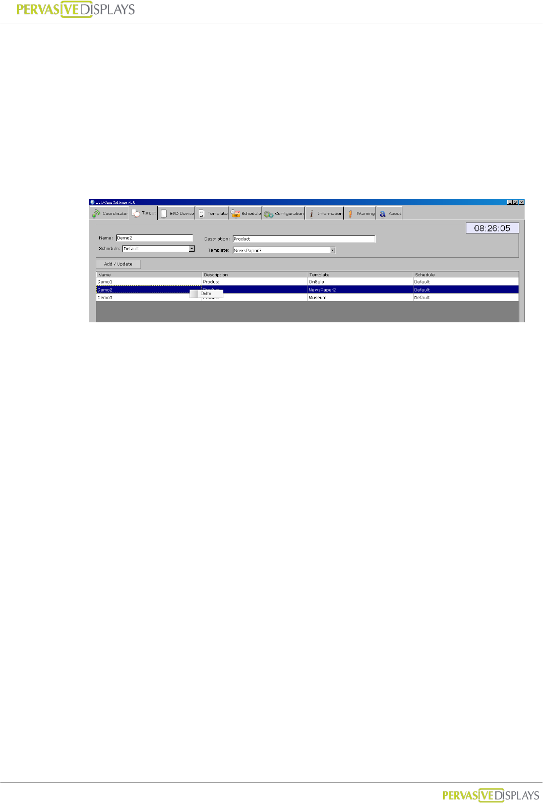
To edit Target:
(1) Click an entry in the list; modify the data and then press [Add / Update] button.
(2) Once the target name is the defined it cannot be changed. If you need to change
the name you can delete the target and create a new one.
To delete Target:
(1) Right click mouse button on a list that you would like to remove, press [Delete] to
remove it.
User Manual of ECO-Sign v1.0
-31-
Confidential
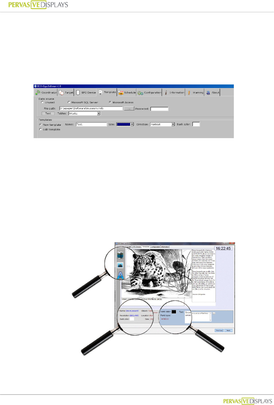
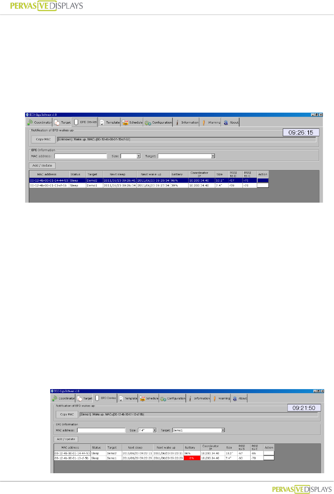
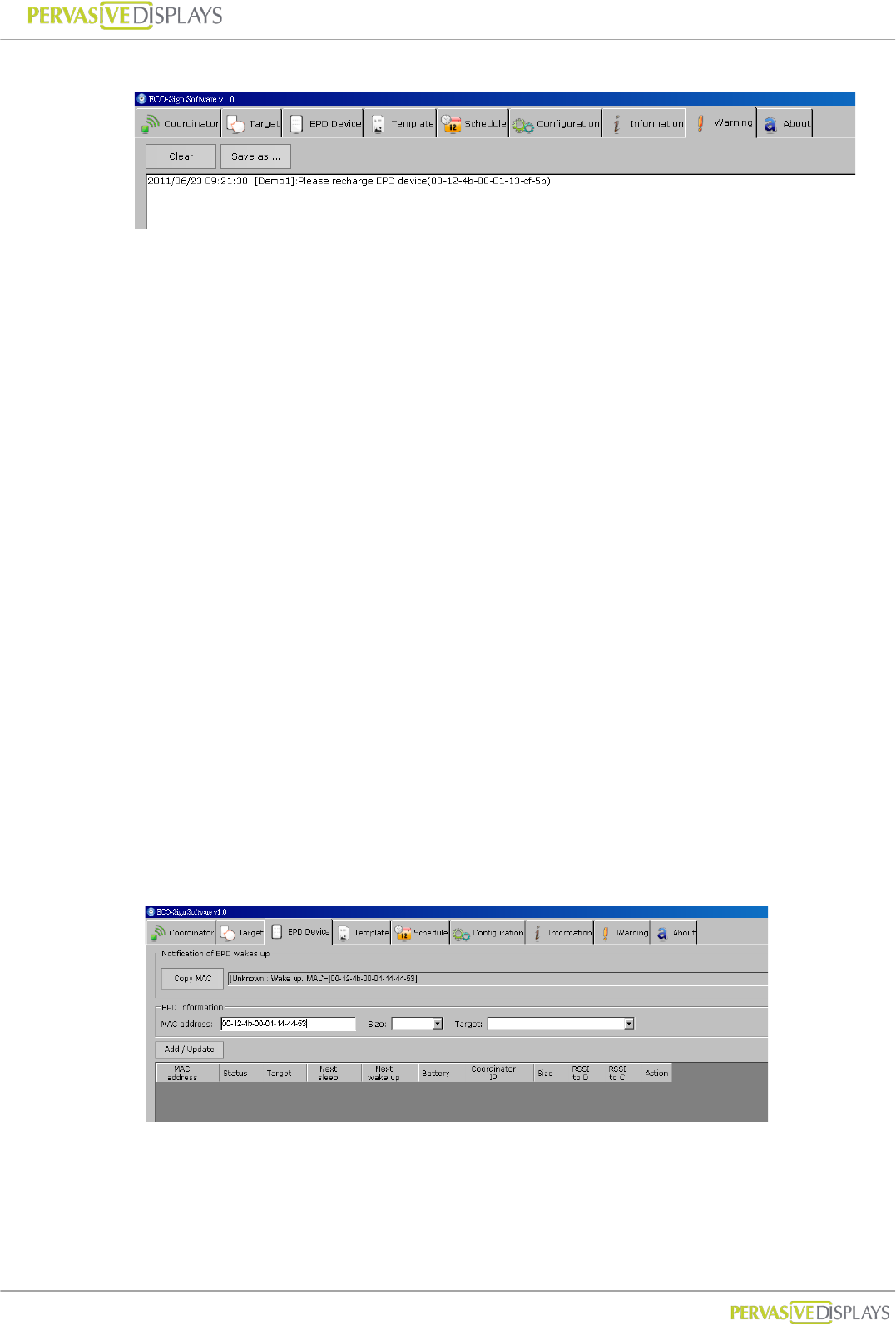
4. EPD Device
When a Device is switched ON or wakes up, the MAC address will be shown in the
“Notification of EPD wakes up” field. If the EPD has not been registered, the message box
of will show a Device named [unknown]. To register a device click the “Copy MAC” button
select the size and target and click “Add/Update”.
Note: the device only works with the same channel of Coordinator.
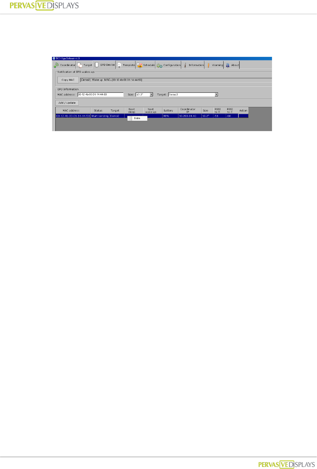
Each field in the grid:
MAC address : The MAC address of ECO-Sign Device which is a 23 character string
in the ##-##-##-##-##-##-##-##, where # is a number [0-9] or a letter
[A-F].
Status: Show the status of the Device i.e. “Wake Up” or “Sleep”.
Target: The target the Device is assigned to.
Next sleep: Shows the time when the Device will enter Sleep mode.
Next wake up: Shows the time when the Device will enter Active mode.
Battery: When the device wakes up, it will transmit the remaining power capacity
to the software. When the value is between 5~10%, please recharge the Device.
When the value is less than 1%, the ESS software will instruct the coordinator to
stop sending data to the Device. The cell will be shown in red color.
User Manual of ECO-Sign v1.0
-32-
Confidential
This will also list a warning message in “Warning” tab strip.
Coordinator IP: This Device is controlled by which Coordinator.
Size: The size of Device.
RSSI: Received Signal Strength Indication which is a measurement of the power
present in a received radio signal.
Signal Strength : (unit=dBm)
0 ~ -25 = Strong, -26 ~ -50 = Good, -51 ~ -75 = Fair, -76 ~ = Weak.
“RSSI to D” means the signal strength from gateway to Device.
“RSSI to C” means the signal strength back to Coordinator.
When RSSI is less than -85 dBm, a router should be added between
Coordinator and Device to enhance signal strength and distance.
To add a new EPD Device:
(1) There are two places to show the waked up message of EPD Device. One is shown
in Information tab strip; another is at the top of this tab “Notification of EPD wakes
up”.
(2) When you switch ON a new Device, the MAC address will show in “Notification of
EPD wakes up” box. Please click [Copy MAC] button and then the MAC address in
“EPD information” will be copied. You can also directly type the MAC address here.
User Manual of ECO-Sign v1.0
-33-
Confidential
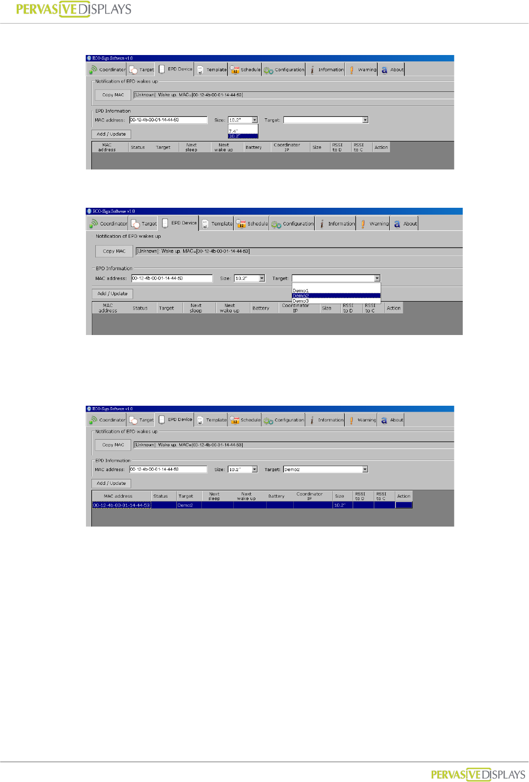
(3) Select right panel size of the Device.
(4) Select a Target name for the EPD Device and assign it.
(5) Click [Add / Update] button to add this EPD Device to list. When the EPD Device
wakes up next time, the message will show correct Target name and work with
Schedule accordingly.
To edit a EPD Device:
(1) Click a list that you would like to edit. Data will be shown on the top fields.
(2) MAC address is the primary key which cannot be changed.
(3) Press [Add/Update] button to finish editing data.
User Manual of ECO-Sign v1.0
-34-
Confidential
To delete EPD Device:
(1) With your mouse right click on the EPD Device that you would like to remove and
select [Delete] from the popup menu.
User Manual of ECO-Sign v1.0
-35-
Confidential
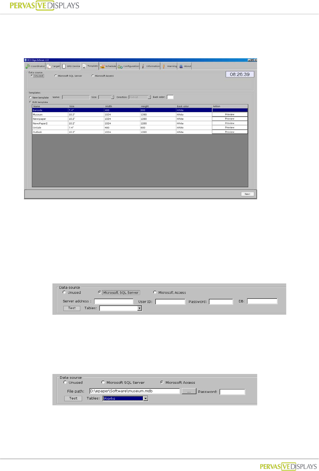
5. Template
ESS provides several objects and connectivity to design different content.
Data Source:
In this group, you just need to set the database connection from Microsoft SQL Server
or Access one time. You can start to drag a database object on the layout and assign
table schema by condition. If your data isn’t from a database, use the “Unused” radio
button option.
(1) Microsoft SQL Server:
Please input a Microsoft SQL Server’s IP address/host name, login user ID,
password and database name in the provided text fields.
Click [Test] to test the connection. If the connection is successful, the Tables in
the database will be listed in the drop-down list.
(2) Microsoft Access:
Click […] button to select an Access database file. The file path will be shown in
the text box. If the Access database is password protected, please input it in the
Password field.
User Manual of ECO-Sign v1.0
-36-
Confidential
Click [Test] to test the connection. If the connection is successful, the tables in the
database will be listed in the drop-down list.
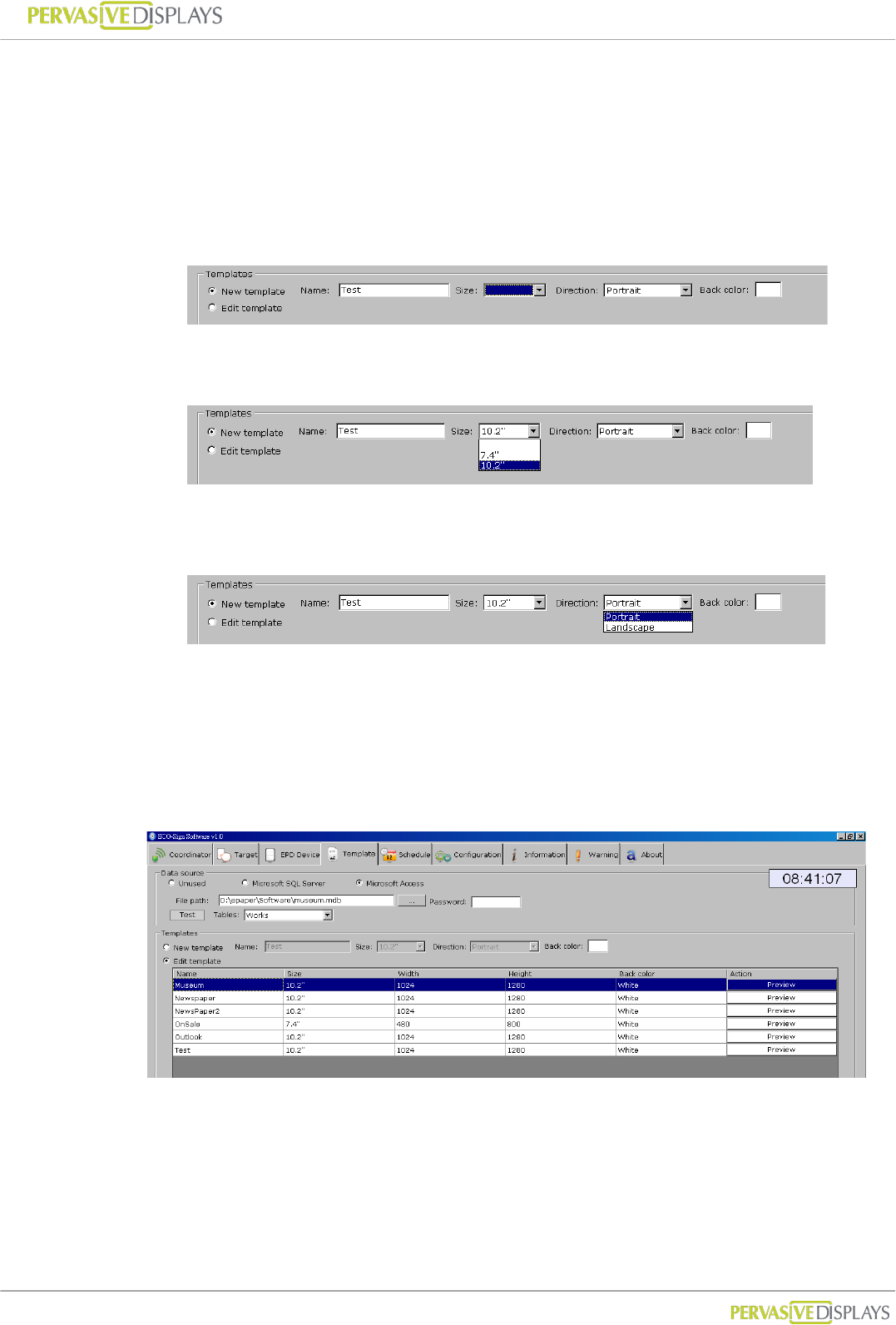
Templates:
1. To add a new template:
(1) Select the [New template] option button and name your template.
(2) Select the size of Template. ESS only “7.4” and “10.2” templates are
supported.
(3) Select Direction. For example, 800x480 pixels is 7.4” landscape direction,
480x800 pixels is portrait direction.
(4) Select the background color. The background color can be either black or
white.
(5) Click [Next] button, the template designer will appear on next screen.
2. To edit a template:
(1) Select [Edit template] option button.
(2) Click on a template that you would like to edit and click [Next] button then.
(3) You can click each “Preview” button to see the final result immediately. The
image will be opened by your system’s default image viewer.
User Manual of ECO-Sign v1.0
-37-
Confidential
3. To delete a template: With your mouse right click on the template that you would
like to remove and select [Delete] from the popup menu.
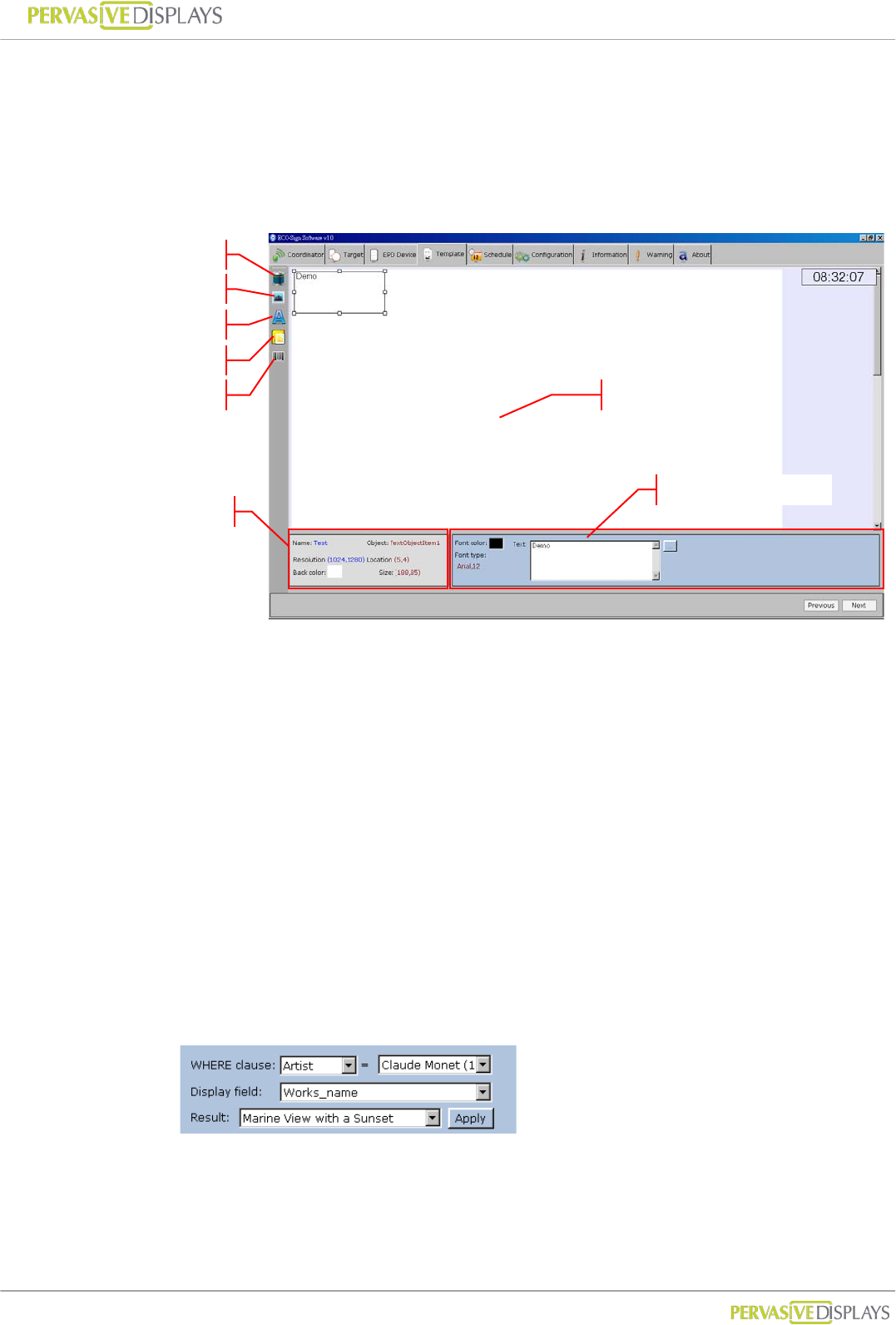
Template Designer:
1. There are at least five objects to design the layout and setup of your template
which are (1) Database (2) Image (3) Text (4) Microsoft Outlook and (5) Barcode
object.
2. Each new object that you clicked will be added to the templates top-left position.
You can press and hold your left mouse button to move the object to the desired
position. You can also drag the borders of object to change the size
3. In object’s property area, you can change font, size or color.
Database object:
You can link a field from a data table of Microsoft SQL Server or Access
database that you’ve set in previous step.
The database object’s property looks like:
WHERE clause:
The WHERE clause is used for extracting the records that fulfill a
specified criterion, likes WHERE string in SQL statement. It only
supports “equal” operator to filter the result only one record fits.
Text Object
Image Object
Database Object
Object’s Property
Design Area
Object’s Information
Outlook Object
Barcode Object
User Manual of ECO-Sign v1.0
-38-
Confidential
Display field:
The field to be shown on Device.
Result:
To show filtered record. Please make sure only one record is returned.
If multiple records are return, you must redefine the WHERE clause.
Press [Apply] to see the result on Template
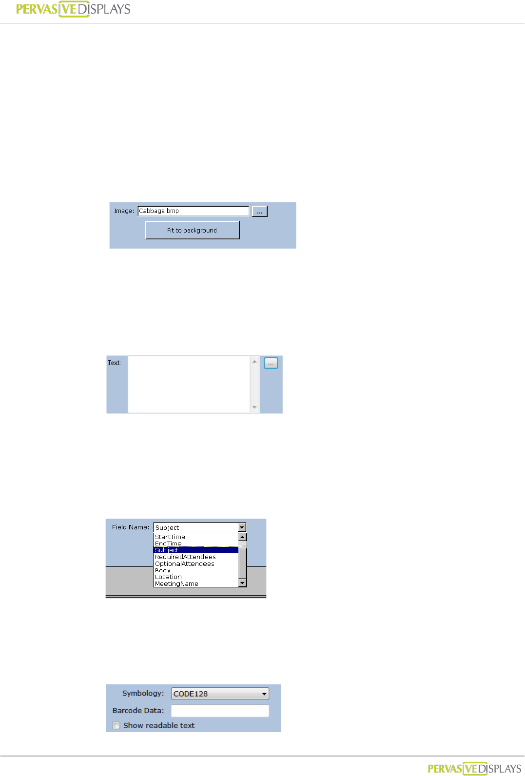
Image object:
The image object’s property:
You can import a .bmp, .jpg, or .png image file onto your template by
pressing […] button. Press [Fit the background] button to scale your
imported image to fit the entire background.
Text object:
The text object’s property:
You can place any text object on the layout to act as a field name or type the
string you want in the box. You also can press "..." button to import the
content from a text file.
Outlook object:
The Microsoft Outlook object’s property:
The field name are given from Microsoft Outlook. You can place the field you
want onto the layout, and then the field will show data according to schedule.
Barcode object:
The Barcode object’s property:
You can select the Symbology of barcode and input the data you would like to
User Manual of ECO-Sign v1.0
-39-
Confidential
show. If your barcode will show text under the barcode, “Show readable text”
option should be checked.
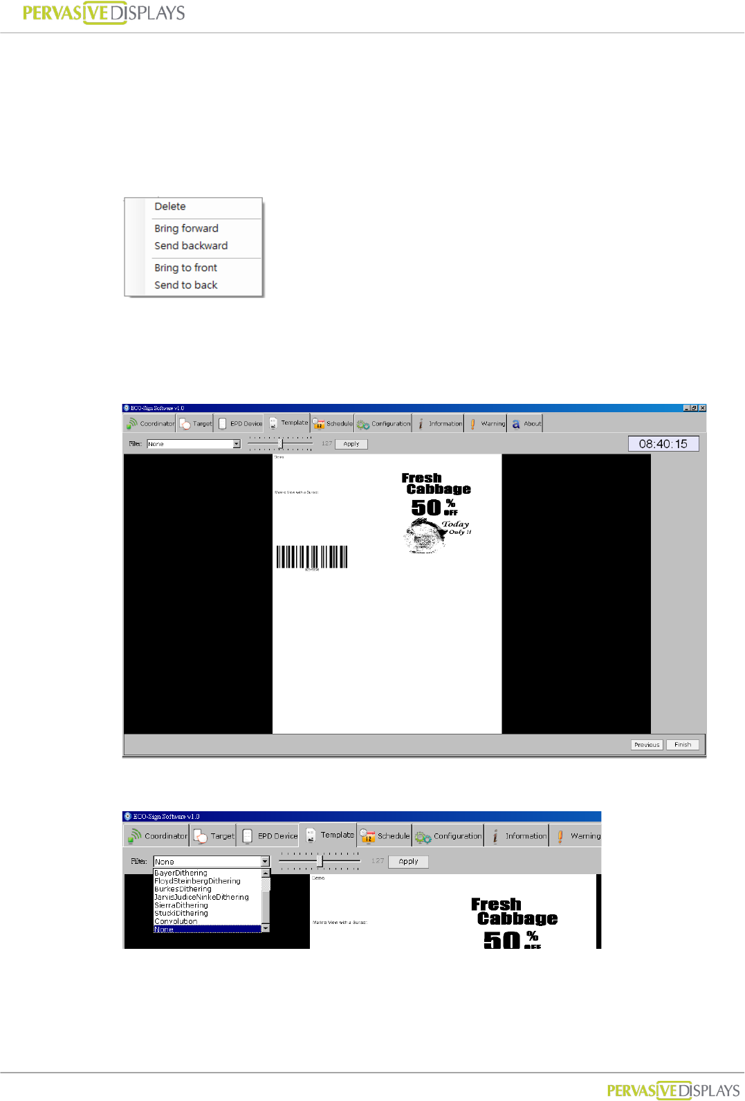
4. If some objects are overlapping, you can right-click the object and choose to
“Bring forward”, “Send backward”, “Bring to front” or “Send to back” on the
pop-up menu. You can also use the "Delete" button to delete an object.
5. When you finish a template, please click [Next] button at the bottom-right
position to preview the generated image. Otherwise, you can click [Previous]
button to go back to the template list.
6. Several filters are provided to help you generate different effects.
7. The page shows the converted image. If okay, press [Finish] button back to
template list.
User Manual of ECO-Sign v1.0
-40-
Confidential
6. Schedule
Schedule provides recurring and unconventional time intervals to configure the Device
active or sleep modes.
Recurring time interval
1. Please switch to “Configuration” page. You can set recurring time here. It is also
the “Default” schedule which can be default selected in Target page to assign this
schedule.
2. This setting is used for test or demo purpose. In real use case, we won’t allow
Device frequently wakes up because it consumes much power.
Unconventional time interval
1. In Schedule tab strip, it allows you to set unconventional time interval to wake up
Devices.
2. Input a new Schedule name in the field and press [Add] button.
3. In the list box, click on the Schedule you just created. You can set the Wake-Up
time in absolute time here. After pressing [Add] button, the new timing will be
appended to right side list box.
4. To delete a timing: With your mouse right click on the time list that you would like
to remove and select [Delete] from the popup menu.
User Manual of ECO-Sign v1.0
-41-
Confidential
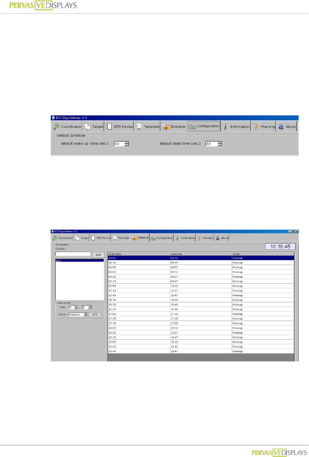
7. Configuration
Default Schedule :
(1) Like the setting above, the Device will wake up for 60 seconds. When it returns to
sleep mode, it will keep sleeping for 60 seconds.
(2) When the Device wakes up, it will check for a new image in the Coordinator. If
the coordinator has an update to the display, the image will be transmitted
immediately. Once the Device is finished receiving image from Coordinator, it will
be assigned a new next wake up time and turns to sleep mode.
(3) If a Coordinator is busy serving other Device, the 30 seconds is used to wait for
Coordinator’s signal. If the waiting Device still can’t get any response from the
Coordinator, it will turn to sleep mode.
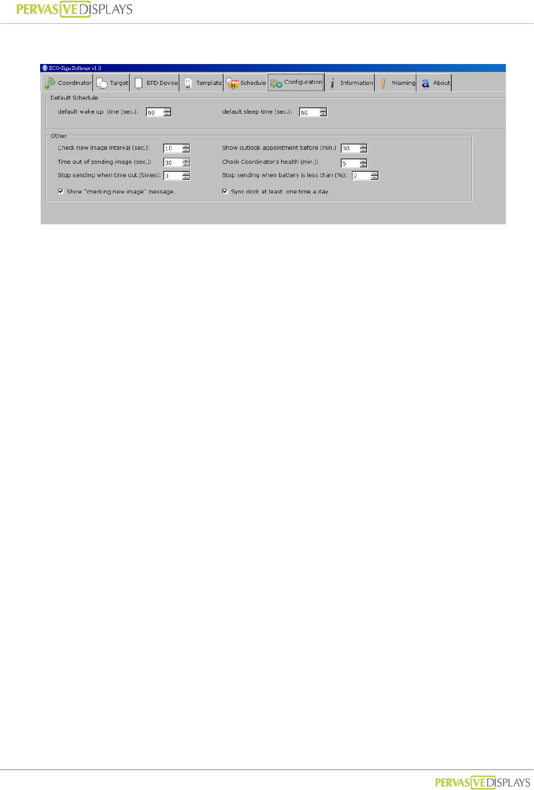
Check new image interval (seconds):
When you change the Template of each Device, ESS has to create new content to
be sent. This setting is to set the interval when ESS to generate new image. When
it’s time to check new image, you can see a message “Checking new images …” is
shown in Information tab strip. If any pixel was changed by user or data, ESS will
generate new image for sending. A message likes “The image of [xxxxx] is ready to
be sent [x].” is shown in Information tab strip as well.
Time out of sending image (seconds):
If Device is receiving data from Gateway but takes a long time without any
response, you should set a time out to interrupt the transmission.
60 seconds is suggested of this sample setting for 7.4”.
90 seconds is for 10.2”.
Stop sending when time out (times)

User Manual of ECO-Sign v1.0
-42-
Confidential
If Device is receiving data from Gateway without any response and time out over
this value, the Coordinator will stop sending image to this Device. A warning
massage will be also recorded in “Warning” tab strip.
If so, you should check:
(1) the distance between Device and Gateway,
(2) Battery capacity of Device,
(3) Interference from any signal.
Show “Check new image…” message
Show this message in the Information tab strip when it’s time to check new image.
Show outlook appointment before (minutes)
This time interval is user for checking coming appointment in Microsoft® Outlook
before how many minutes.
Check Coordinator’s health (minutes)
The time interval is used for checking the health of the Coordinator.
Stop sending when battery is less than (%)
If the percentage of Device’s battery capacity is less than this value, ESS software
will instruct the coordinator to stop sending data to this Device.
Sync clock at least one time a day
If Device has set to sleep over a day, you can checked this option to allow Device
wakes up one time per day to sync clock and check its battery capacity. This time
will be booked at 23:59:00.
User Manual of ECO-Sign v1.0
-43-
Confidential
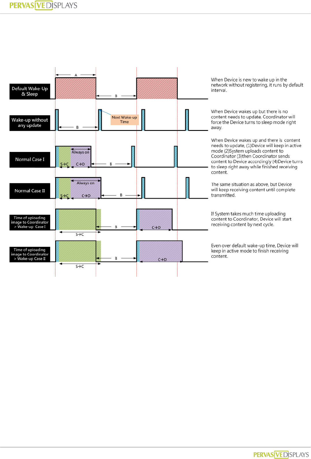
8. How does Eco-Sign work?
A : Default Active(Wake-up) Time, B : Default Sleep Time,
SC : Eco-sign System to Coordinator, CD : Coordinator to Device
User Manual of ECO-Sign v1.0
-44-
Confidential
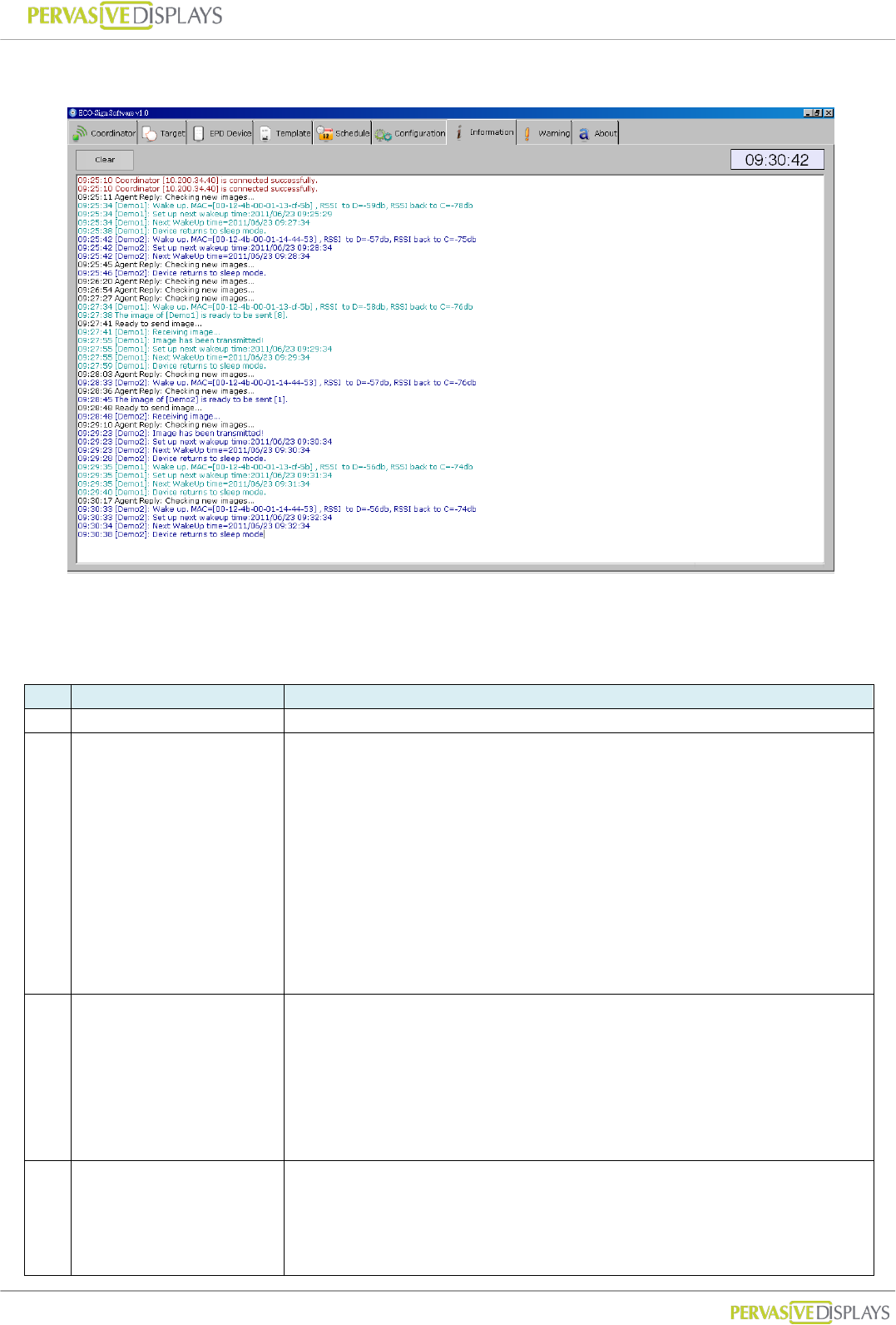
9. Information
The message box shows the communication log of Coordinators and Devices. Below is an
example.
Message format: [HH:MM:SS]: [Information]
Item
Description
Log
1
Coordinator is working.
14:19:23 Coordinator [10.200.34.29] is connected successfully.
2
Switch ON Device
sequentially.
Whatever Device wakes up
first time, ESS will force
Devices queued up to set
next wake up time and turn
to sleep.
14:19:57 Agent Reply: Checking new images...
14:20:49 [Demo1]: Wake up. MAC=[00-12-4b-00-01-13-ce-1d] , RSSI to D=-30db, RSSI back to C=-51db
14:20:49 [Demo1]: Set up next wakeup time:2011/04/28 14:25:18
14:20:52 [Demo1]: Next WakeUp time=2011/04/28 14:25:18
14:20:54 [Demo1]: Device returns to sleep mode.
14:21:00 Agent Reply: Checking new images...
14:22:06 Agent Reply: Checking new images...
14:22:19 [Demo2]: Wake up. MAC=[00-12-4b-00-01-13-cf-64] , RSSI to D=-23db, RSSI back to C=-41db
14:22:19 [Demo2]: Set up next wakeup time:2011/04/28 14:26:48
14:22:23 [Demo2]: Next WakeUp time=2011/04/28 14:26:48
14:22:24 [Demo2]: Device returns to sleep mode.
14:23:10 Agent Reply: Checking new images...
14:23:50 [Demo3]: Wake up. MAC=[00-12-4b-00-01-13-cf-41] , RSSI to D=-39db, RSSI back to C=-59db
14:23:50 [Demo3]: Set up next wakeup time:2011/04/28 14:28:18
14:23:53 [Demo3]: Next WakeUp time=2011/04/28 14:28:18
14:23:54 [Demo3]: Device returns to sleep mode.
3
Time to generate new image.
You can find “Configuration”
page “Check new image
interval (minutes)” to set this
timer.
You can uncheck「Show
“Check new image…”
message」not to show this
message.
14:24:13 Agent Reply: Checking new images...
14:25:18 Agent Reply: Checking new images...
4
You can check the wake up
timing at item 3 that had
marked by different color.
At item 2, the new images
were generated. When
Device wakes up, ESS will
14:25:19 [Demo1]: Wake up. MAC=[00-12-4b-00-01-13-ce-1d] , RSSI to D=-31db, RSSI back to C=-51db
14:25:22 The image of [Demo1] is ready to be sent [5].
14:25:25 Ready to send image...
14:25:26 [Demo1]: Receiving image...
14:25:42 [Demo1]: Image has been transmitted!
14:25:42 [Demo1]: Set up next wakeup time:2011/04/28 14:29:48
14:25:45 [Demo1]: Next WakeUp time=2011/04/28 14:29:48

User Manual of ECO-Sign v1.0
-45-
Confidential
transmit the image to Device
immediately.
“Receiving image...” means
Coordinator is transmitting
image to Device.
Once the image is transferred
completely, you will find
“Image has been
transmitted!” message and
the Device is rescheduled to
next wake up time. Turn to
sleep then.
14:25:47 [Demo1]: Device returns to sleep mode.
14:26:21 Agent Reply: Checking new images...
14:26:48 [Demo2]: Wake up. MAC=[00-12-4b-00-01-13-cf-64] , RSSI to D=-24db, RSSI back to C=-43db
14:26:53 The image of [Demo2] is ready to be sent [4].
14:26:56 Ready to send image...
14:26:56 [Demo2]: Receiving image...
14:27:12 [Demo2]: Image has been transmitted!
14:27:12 [Demo2]: Set up next wakeup time:2011/04/28 14:31:18
14:27:15 [Demo2]: Next WakeUp time=2011/04/28 14:31:18
14:27:16 [Demo2]: Device returns to sleep mode.
14:27:25 Agent Reply: Checking new images...
14:28:19 [Demo3]: Wake up. MAC=[00-12-4b-00-01-13-cf-41] , RSSI to D=-46db, RSSI back to C=-66db
14:28:23 The image of [Demo3] is ready to be sent [2].
14:28:26 Ready to send image...
14:28:26 [Demo3]: Receiving image...
14:28:29 Agent Reply: Checking new images...
14:28:45 [Demo3]: Image has been transmitted!
14:28:45 [Demo3]: Set up next wakeup time:2011/04/28 14:32:48
14:28:49 [Demo3]: Next WakeUp time=2011/04/28 14:32:48
14:28:51 [Demo3]: Device returns to sleep mode.
5
You can also check the “Next
WakeUp timing” in item 4
that had marked by different
color.
Devices are going to work to
follow such rule in the future.
If the image was not
transmitted successfully, it
will show “Time out of
transmitting image” in the
message box.
You could find the time out
setting at “Configuration”
page “Time out of sending
image (seconds)”.
14:29:32 Agent Reply: Checking new images...
14:29:49 [Demo1]: Wake up. MAC=[00-12-4b-00-01-13-ce-1d] , RSSI to D=-37db, RSSI back to C=-57db
14:29:54 The image of [Demo1] is ready to be sent [6].
14:29:57 Ready to send image...
14:29:57 [Demo1]: Receiving image...
14:30:13 [Demo1]: Image has been transmitted!
14:30:13 [Demo1]: Set up next wakeup time:2011/04/28 14:34:18
14:30:17 [Demo1]: Next WakeUp time=2011/04/28 14:34:18
14:30:18 [Demo1]: Device returns to sleep mode.
14:30:37 Agent Reply: Checking new images...
14:31:19 [Demo2]: Wake up. MAC=[00-12-4b-00-01-13-cf-64] , RSSI to D=-25db, RSSI back to C=-44db
14:31:24 The image of [Demo2] is ready to be sent [3].
14:31:27 Ready to send image...
14:31:27 [Demo2]: Receiving image...
14:31:40 Agent Reply: Checking new images...
14:31:43 [Demo2]: Image has been transmitted!
14:31:43 [Demo2]: Set up next wakeup time:2011/04/28 14:35:48
14:31:46 [Demo2]: Next WakeUp time=2011/04/28 14:35:48
14:31:47 [Demo2]: Device returns to sleep mode.
14:32:44 Agent Reply: Checking new images...
14:32:50 [Demo3]: Wake up. MAC=[00-12-4b-00-01-13-cf-41] , RSSI to D=-39db, RSSI back to C=-57db
14:32:54 The image of [Demo3] is ready to be sent [5].
14:32:57 Ready to send image...
14:32:57 [Demo3]: Receiving image...
14:33:11 [Demo3]: Image has been transmitted!
14:33:11 [Demo3]: Set up next wakeup time:2011/04/28 14:37:18
14:33:14 [Demo3]: Next WakeUp time=2011/04/28 14:37:18
14:33:15 [Demo3]: Device returns to sleep mode.
User Manual of ECO-Sign v1.0
-46-
Confidential
IX. How to update firmware?
ECO-Sign Firmware Update is a standalone tool provided for updating or restoring
firmware, factory default, change ZigBee channel ID to Coordinator, Router and Device.
Please do confirm the HEX file of Device/Router/Coordinator is the correct type before
updating firmware.
Please be noted that update firmware failure can permanently damage your device, so
take extreme caution when executing this operation. Make sure you have the correct
firmware versions. Update the firmware only if you really need to.
1. Naming rule
The table below shows the naming convention:
Bit 1 2~5 _ 7,8 _ 10~13 .hex
Description
D:Device
R:Router
C:Coordinator
Version#.## underline Channel
ID underline PAN ID Hex
file
For example:
D0.53_20_1688.hex
C0.55_12_1678.hex
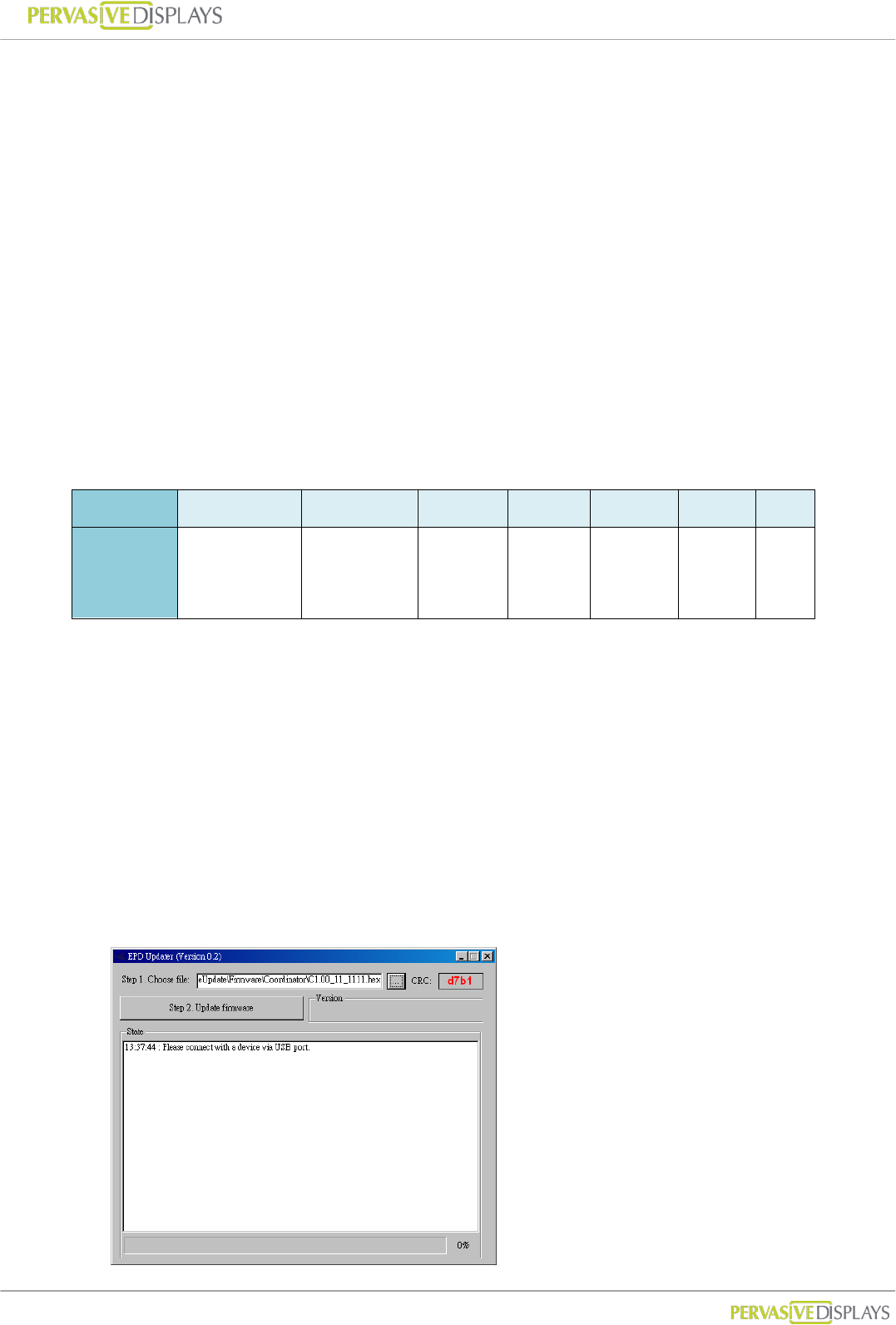
2. Update tool
(1) Please connect a device with your computer via USB cable. At device side, it’s a
mini-USB port. (The device here can be Coordinator, Router or Device.)
(2) Execute “ESS_Updater_V0.2.exe” file. You can request this tool from us.
User Manual of ECO-Sign v1.0
-47-
Confidential
(3) Choose a HEX file that you would like to update. Please do check it matches the device
type in advance. After choosing the correct HEX file, the form will show a CRC number.
(4) Please switch the device ON.
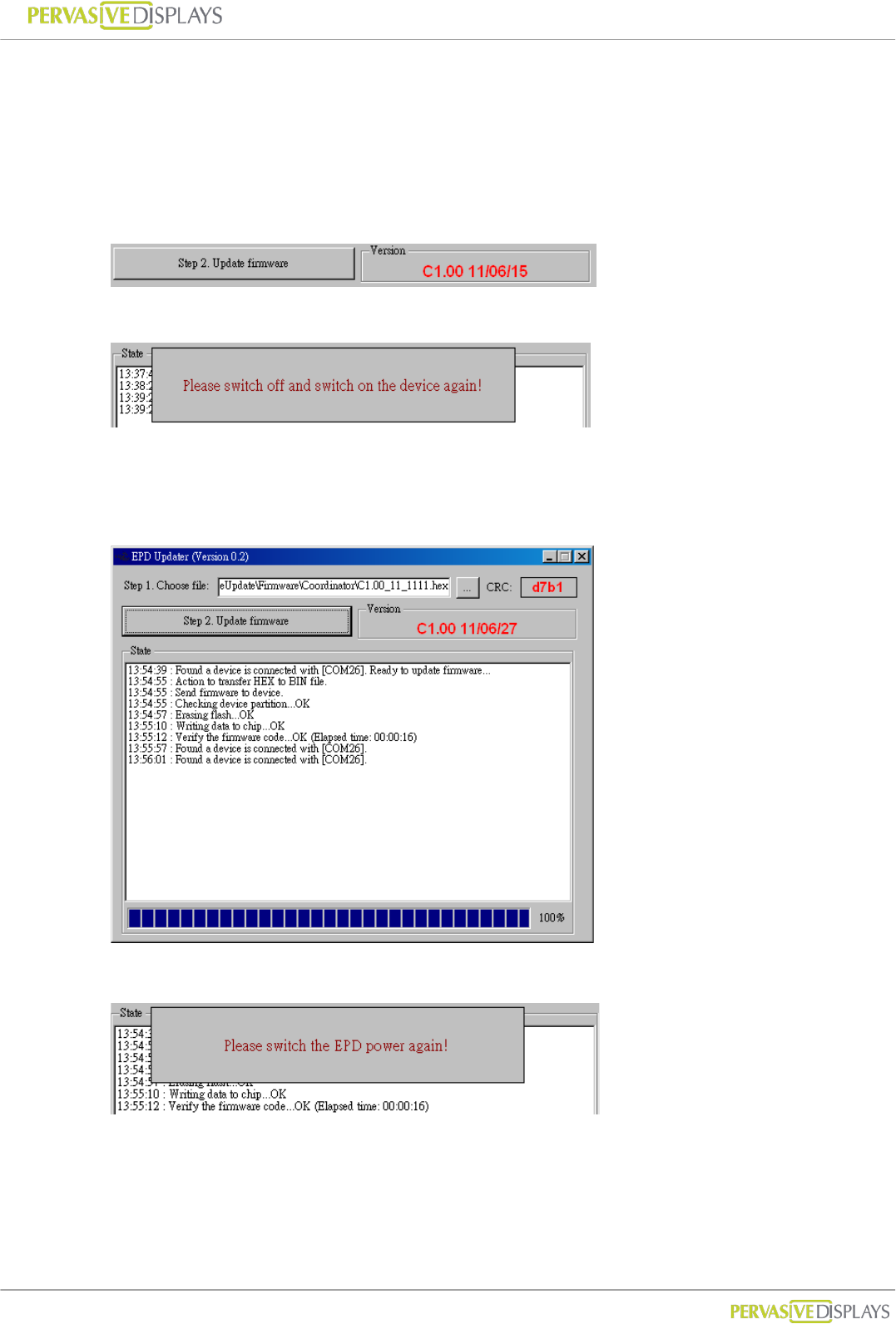
(5) Click [Step 2. Update Firmware] button to start updating the new firmware. The
current firmware version of device is shown in “Version” area:
(6) You will be asked to switch the device OFF and ON again. Please proceed.
(7) After switching the device ON, the tool is going to start updating firmware. Please wait
for the message “Verifying the firmware code...OK (Elapsed time: 00:00:##)”.
If failed, if the update fails repeat step (2).
(8) You’ll be asked to power cycle the device again. Please proceed.
(9) When you return to the tool, you will find the new firmware version.
(10) Switch OFF the device and exit the tool. The device is updated successfully.
Federal Communication Commission Interference Statement
This equipment has been tested and found to comply with the limits for a Class B
digital device, pursuant to Part 15 of the FCC Rules. These limits are designed to
provide reasonable protection against harmful interference in a residential installation.
This equipment generates, uses and can radiate radio frequency energy and, if not
installed and used in accordance with the instructions, may cause harmful interference
to radio communications. However, there is no guarantee that interference will not
occur in a particular installation. If this equipment does cause harmful interference to
radio or television reception, which can be determined by turning the equipment off
and on, the user is encouraged to try to correct the interference by one of the
following measures:
. Reorient or relocate the receiving antenna.
. Increase the separation between the equipment and receiver.
. Connect the equipment into an outlet on a circuit different from that to which the
receiver is connected.
. Consult the dealer or an experienced radio/TV technician for help.
FCC Caution: To assure continued compliance, any changes or modifications not
expressly approved by the party responsible for compliance could void the user's
authority to operate this equipment. (Example - use only shielded interface cables
when connecting to computer or peripheral devices).
FCC Radiation Exposure Statement
This equipment complies with FCC RF radiation exposure limits set forth for an
uncontrolled environment.
This transmitter must not be co-located or operating in conjunction with any other
antenna or transmitter.