PIONEER Receivers Manual L0202065
User Manual: PIONEER PIONEER Receivers Manual PIONEER Receivers Owner's Manual, PIONEER Receivers installation guides
Open the PDF directly: View PDF ![]() .
.
Page Count: 52
AU
VS
VS
VS
D
8
10S
10S
50S
Instructions
_Arl RI i ill f_
Vv/_rtl_lll_l_l: TO PREVENT FIRE OR SHOCK
HAZARD, DO NOT EXPOSE THIS APPLIANCE TO
RAIN OR MOISTURE,
THE STANDBY/ON BUTON IS SECONDARY
CONNECTED AND THEREFORE DOES NOT
SEPARATETHE UNIT FROM MAINS POWER
IN STANDBY POSITION.
IMPORTANT
The llghtning flash with arrowhead symbol
wTthln an equilateral triangle, is intended to
a_ert the user to the presence of uninsul;_ted
"dangerous voltage N w_thln the product's
erlc_osu re that may be of £uff_c_ent m;_g[li[ude
to constitute a rTsk of elect rlc shock to persor_s.
CAUTION
CAUTION:
TO PREVENT THE RiSK OF ELECTRIC SHOCK,
DO NOT REMOVE COVER IOR BACKI. NO
USER SERVICEABLE PARTS INSIDE. REFER
SERVICING TO QUAMFIED SERVICE
PERSONNEL.
The excJarrlatlon point within an equilateral
[rla[lgle is intended to amert the user [o the
presence of important opera[ing and
maintenance Iserv_clng) in_truc[ions in the
JTterature accompanying tile appJlance.
NOTE: This equipment has been tested and found to compiy with the limits for a Class B digital device,
pursuant to Part 15 of the FCC Rules. These limits are designed to provide reasonable protection against harmful
interference in a residential installation. This equipment generates, uses, and can radiate radio frequency energy
and, if not installed and used in accordance with the instructions, may cause harmful interference to radio
communications. However, there is no guarantee that interference will not occur in a particular installation. If
this equipment does cause harmful interference to radio or television reception, which can be determined by
turning the equipment off and on, the user is encouraged to try to correct the interference by one or more of the
following measures:
-Reorient or relocate the receiving antenna.
-Increase the separation between the equipment and receiver.
- Connect the equipment into an outlet on a circuit different from that to which the receiver is connected.
- Consult the dealer or an experienced radioFV technician for help.
IMPORTANT NOTICE
The serial number for this equipment is located on the
rear panel. Please write this serial number on your en-
closed warranty card and keep it in a secure area. This
is for your security.
[For Canadian model]
This Class B digital apparatus complies with
Canadian ICES-003.
[Pour le modele Canadien]
Cet appareil num6rique de la classe Best
conforme a la norme NMB-003 du Canada.
Manufactured under license from Dolby Labo-
ratories. "Dolby", "Pro Logic" and the double-D
symbol are trademarks of Dolby Laboratories.
Confidential Unpublished Works. ©1992-1997
Dolby Laboratories, Inc. All rights reserved.
[For U.S. model]
As an ENERGY STAR ® Partner, Pioneer
Corporativn has dcter_aincdthatthisproduct meets
the E_ERGY STAR ® guidelines for energy
e_cie_cy, he1 Ea
[For Canadian model]
CAUTION: TO PREVENT ELECTRIC SHOCK DO NOT
USE THIS (POLARIZED) PLUG WITH AN EXTENSION
CORD, RECEPTACLE OR OTHER OUTLET UNLESSTHE
BLADES CAN BE FULLY INSERTEDTO PREVENT BLADE
EXPOSURE.
ATTENTION: POUR PREVENIR LES CHOCS
ELECTRIQUES NE PAS UTILISER CETTE FICHE
POLARISEE AVEC UN PROLONGATEUR, UNE PRISE DE
COURANT OU UNE AUTRE SORTIE DE COURANT,
SAUF SI LES LAMES PEUVENT ETRE INSERESS A
FOND SANS EN LAISSER AUCUNE PARTIE A
DECOUVERT.
"DTS", "ES" and "D TS Digital Surround" are
trademarks of Digital Theater Systems. Inc.
Manufactured under license from Digital
Theater Systems, Inc.
If the socket outlets on the associated equipment are not
suitable for the plug supplied with the product, the plug must
be removed and an appropriate one fitted. Replacement and
mounting of an AC plug on the power supply cord of this unit
should be perfomed only by qualified service personnel. The
cut-off plug must be disposed of as an electrical shock hazard
could exist if connected to a socket outlet. H022AE.
Information to User
Alteration or rnodifications carried out without appropriate authorization may invalidate the user's right to
2 operate the equipment,
En
IMPORTANT SAFETY INSTRUCTIONS
READ INSTRUCTIONS -- A] tie safety
and operating instruct_ol/s Should be
re_d before the product is operated
RETAIN INSTRUCTIONS-- The safety a nd
operating instructioT1s should be _etained
for futu{e refere_/ee
HEED WARNINGS All warnings on the
product and in the operating instructions
should be _dhered to
FOLLOW INSTRUCTIONS -- All operating
and use instructions should be f ollowed
CLEANING m Unplug this p_duct from the
w_l_ outlet before clealling Tile product
should be cleaned only with _ polishing
cloth or _ soft dry cl_h Never cle_n
wJt/1 lurnit u_ w_×. benzine, il/secticides
or other vo_ati_e liquids since they m_y
corrode the cabJ_/et
ATTACHMENTS m Do not use attachmel/_
not {ecom_e_lded by the p{oduct
maT_ulacturer _s they may c_use
haza_s
WATER AND MOISTURE -- Do not use
this p_oduct near w_ter for exa_ple.
neat a bathtub, wash bowl. kitchen sink.
or laundry tub; in a wet basement; or
near a swimming pool; al/d the like¸
ACCESSORIES m Do not pl_ce this product
O_l _l u_/st_ble cart. stand, tripod.
bracket, or table The product may fall.
causing serious injury t o a child or _dult.
and serious damage tothe product Use
only with a cart. st al/d. tripod, b_cket.
or table {eco_ended by the
m_nufacture{, or so_d with the product¸
Any meuntil/_ of the p_duct should
lo_low the m_nufactu{e{'s i_/st{uctions.
and sI_ould use a _ouT_ting accessory
recommended by the m_nufactu{e{
CART -- A product and cart combination
should be moved with care Quick ste_s.
e×cessive lorce, arid uneven/ surfaces
m_y c_use the product and ca_t
cow,binaries/to ovettur_/
VENTILATION -- Slots alld open ngs in tie
cabinet are provided for refit latiofl and
to ensu{e {eliable operation of the
p_educt a_/d to protect it from
overheating, arid these ope_/J_/gS must
n_ be blocked or covered¸The opel/ings
should never be b_ocked by placing the
p_oduct on a bed, soia, ru_, or other
similar surface¸ This product S/lould not
be placed ill a buil_in installation such
as _ bookcase or {ack unless proper
ventilatioll is provided or the
n/a_/ufacturer s inst{uctions have bee_/
adhered to
POWER SOURCES w This product should
beoperated only from thetype of power
source il/dicated oil the marking I_bel If
you are net sure oi the type of power
su[_ply to your hol_e, COilSult your
p_oduct dea_e{ or local power com pa_/y
LOCATION The appli_l/ce should be
inst_lled in a stable IocatioT_
NONUSE PERIODS The power cord of
the appliallce should be ul/plugged f _m
tile Outlet whefl left _llused for _ long
period of time
GROUNDING OR POLARIZATION
• f this product ;s equipped with a
polarized alterl/_t_ng current line plug {a
plug havJl/g ol/e b_ade w_der thall the
other}, it w_ll fit il/to the outlet only one
w_¥ T/lis is a safety le_{ture If you are
unable to insert the p_u_ fully il/to the
outlet, try reversing the plug _f the plug
should still fail to fi_, contact your
electrician/ to replace your obsolete
outlet¸ Do not defeat tile safety purpose
of the polarized p_ug
• If this ploduct is equipped with a three
w_re grounding type plug, _ p_ug having
a third (grou ndillg} pin, it will on_y fit il/to
a grounding type power outlet Th_s is a
safety feature If you a re unable to inse{t
the plug into the outlet, cont_{ct your
electrician/ to replace your obsolete
outlet¸ Do n_ defeat tile safety purpose
of the groul/ding type plug¸
POWER-CORD PROTECTION -- Power
supply cords should be routed SO that
they are not likely to be walked oil or
piTlched by items p_aced upon or _gainst
therl/, pa_ng pal L_cular attention to cores
at p_ugs, convenie_/ce r ece[_tacles, and
the point w_lele they exit Iron/ the
product¸
OUTDOOR ANTENNA GROUNDING -- If
an outside _nten_/_ or c_ble system is
CO_l_ected to the product, be su{e the
anten_/_ or c_ble syst eT_qis grounded so
as to provide so_e protectlOT_ _gainst
voJtage surges and bu_Jt up static
charges¸ Article 810 of the Nationa_
Electrical Code,ANSI/NFPA 70, provides
information witI1 /ega/d to proper
_roundil/g of the mast al/d SUpporting
structure, _roundil/g el the lead in wire
to a_/ a_/te_/na discharge unit, size of
_roundi_/g conductors, location of
anten_/_ discharge unit, con_/eCtlOT_ to
_r OU_ldi_/g elect r odes, a_d requl{emef_t s
Ior the grounding electrode¸ See Figure
A
LIGHTNING m For _dded protection f or t his
product duriTl_ a lightl/in_ storr¢l, or when
it is lelt unattended al/d unu£ed ior long
periods of time, ul/plug it from the w_ll
outlet and disCO_l_eCt the ar_tef_na or
cable Systel_ This will prevel/t damage
to the product due to lightning and
powe/ line surges¸
POWER LINES m An outside antenl/a
systeT/q should not be located in the
vicinity of overhead power lines or other
elect r_c light or power Cl/Cuits, or where
it can f_{lli_to such power lilies or circuits
When installing an outside arlterlna
system, extre_e care should be taken
to keep from touchillg such power lilies
or circuits _s contact with them migt_t
be f_tal
OVERLOADING -- Do not oveflo_d w_ll
outlets, exte_/sio_l cords, or integral
CO_lVe_/le_/ce receptacles as this c_n
result in _ risk of life or elect r_c shock¸
f
OBJECT AND UOUID ENTRY -- Never
push obiects of ally kiTld into this product
th{ougl_ openings as they may touch
d_ngerous voltage points or short-out
p_rls that could/esult in _ fire or e]ect/ic
shock Never spill liquid of ally k_nd OT1
the product
SERVICING -- Do not aLtem[_t to service
this p_oduct yourself as opening or
_e_ovi_/_ covers may expose you to
d_ngerous voltage or other hazards¸
Refer _11 servicing to qualified service
person_/el
DAMAGE REQUIRING SERVICE-- U_/plug
this product f/om the wall outlet al/d
lefer servicing to qualified service
pe/sonl/el unde/ the follow_l/g
conditions
• When tile power supply cord or p_ug is
d_maged
• If liquid has been spilled, or objects
i/_ve fallen il/te the product¸
• If the product has beel/exposed to r_i_
or water¸
• I f the p_oduct does not ope{ate normally
by following the operating _nstructions
Adjust only those controls that are
covered by the ope{ating instructio_/s
as an improper _djustme_/t of othe{
controls may result in dal_age _nd will
ofter_ require extensive work by
qualified teclll/_ci_{l/ to restore the
p_oduct to its hernial operation
• If the product has been dropped el
d_n/aged ill ally w_{y
• When the product exhibits a distinct
cha_/ge in per form_nce this indicates
a _/eed for service
REPLACEMENT PARTS m Whe_/
{ep_acerne_lt pa{ts _re required, be sure
the service teCil_lCla_/ has used
leplacement parts specified by the
manufacturer o{ have the sam÷
characteristics as the origina_ part¸
Ui/autholized substitutions n/ay/esu_t
in life, electric shock, or other hazards¸
SAFETY CHECK-- U poll completiOll _ any
service or repairs to this product, ask
the service technician to pe{for_ safety
checks to determine th_{t the product is
in ploper operating condit_oll
WALL OR CEILING MOUNTING -- The
product should not be mou_/ted to
wa_! or ceiling¸
HEAT -- The ploduct should be situated
away f{om heat sources such _s
_adiators, heat r eg_ster s, stoves, or othe_
products {including amplifiers} that
p_oduce i/eat
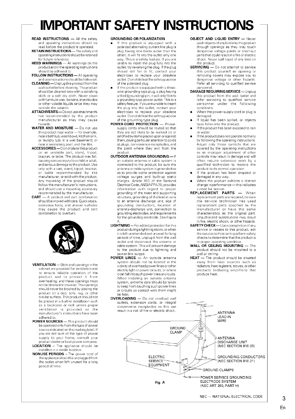
ANTENNA
_LEAD IN
WIRE
ELECTRIC _J GROUNDING CONDUCTORS
_{NEC SECTION 810 21)
EQUIPMENT
ROUND CLAMPS
EQUIPMENT
POWER SERVICE GROUNDING
Fig. A ELECTRODE SYSTEM
(NEC ART 250, PART H)
NEC NATIONAL ELECTRICAL CODE 3
ER
Checking the Supplied
Accessories
Please check that you%e received tile k_llowing supplied
accessories:
•AM loop antenna
• FM wire antenna
•Dry (;eli Batteries x2
(VSX D7105/D8103 : type AA IEC R6P)
(VSX D8505 : type AA IEC LR6)
•Remote Control Unit
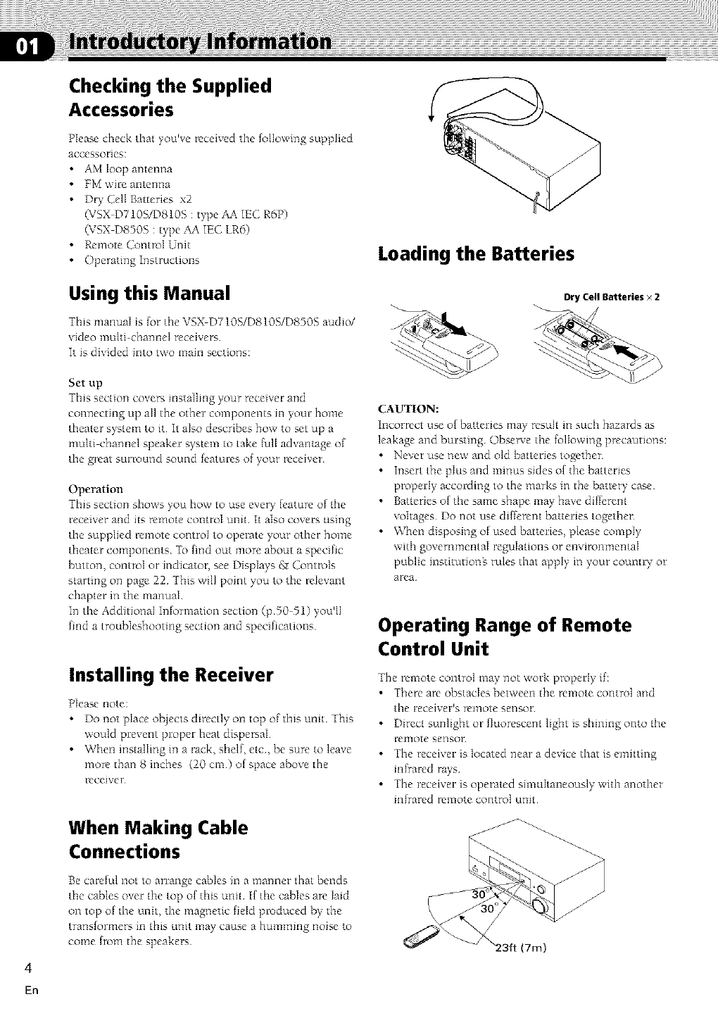
Operating Instructions Loading the Batteries
Using this Manual
Thks manual Js for tile _,SX'.... D 710S/DS10S/DS>0S'- au&o/
Ndeo multi-channel receh'ers
It is divided into t\_o main sections:
Dry Cell Batteries x2
Set up
This section cover', installing your receiver and
connecting up aI1the other components m your home
theater system to it It also describes how to set up a
multi channel speaker system to take {ulI advantage of
the great surround sound features of your receiver
Operation
This section shows you how to use every [eature of the
receiver and its remote control unit It also covers using
the supplied remote control to operate your other home
theater components To hnd out more about a specific
button, control or indicator, see Displays gr Controls
starting on page 22 This wilI point you to the relevant
chapter in the manual
In the Additional Information section (pg0 51) you'll
find a troubleshooting section and specifications
Installing the Receiver
Please note:
•Do not place objects directly on top of this unit This
would prevent proper heat dispersal
• When instalIing in a rack, shelf, etc, be sure to leave
more than 8 inches (20 cm) of space above the
receiver
CAUTION:
Incorrect use of batteries may result in such hazards as
leakage and bursting ()bserve the following precautions:
• Never use new and old batteries together
• Insert the plus and minus sides of the batteries
properly according to the marks in the batte% case
•Batteries of the same shape may have differem
voltages Do not use different batteries together
• When disposing of used bat reties, please comply
with govemmentaI regulations or environmental
public institutiong rules that apply in your country m
area
Operating Range of Remote
Control Unit
The remote control may not work properly if:
• There are obstacles between the remote control and
the receiver% remote sensor
• Direct sunligllt or fluorescent light is shhlhlg onto the
remote sensor
• The receiver is located near a device that is emitting
infrared rays
• The receiver is operated simultaneously with another
infrared remote control unit
When Making Cable
Connections
Be careful not to arrange cables in a manner that bends
the cables over the top of this unit I[ the cables are laid
on top of the unit, the magnetic field produced by the
transIormers in this unit may cause a humming noise to
come from the speakers (7m)
En
Congratulations on buymg this fine Pioneer product
Please read through these operating instructions so you wilI know how to operate your model
properly Aher you have hnished reading tile instructions, put them away ill a safe place for
future reference
01
02
03
Introductory Information 4
Checking the Supphed Accessories 4
Using this Manual 4
Installing tile Receiver 4
When Making (]able Connections 4
|oadingthe Batteries 4
Operating Range of Remote Control Unit 4
Contents 5
Connecting Your Equipment 6
AudiofVideo Cords 6
Digital audio Cords/Optical Cables 6
Connecting Digital Components 6
Example Connection lot a DVD/LD or LD Player 7
Connecting Audio Componems 8
Connecting DVD 71 Channel (51 for VSX D710S)
Components 9
ConnectingVideo Componems 10
Connecting Antennas 11
Connecting Speakers (VSX D7103) 12
Connectmg Speakers (VSX D810S/D850S) 13
Hints on Speaker Placement 14
Connectmg Additional Amplifiers (VSX D810S/
D8505 only) 15
AC Outlet [switched 100 W (08 A) max] 15
04 Preparations 16
Setting Up lor Surround Sound 16
Setting tile Volume/cveI of Each (]hannel 21
05 Displays & Controls 22
Front Panel 22
Display 23
Remote Control (VSX D710S/D8103) 24
Remote Control (VSX D8505) 26
LCD Display (VSX D850S only) 26
06 Sound Modes 27
|earning about tile Sound Modes 27
Switching ANALOG/DIGITAL Signal Input 29
Playing Sources with Dolby Digital m
DTS Sound 29
Selecting a Sound Mode 30
O7
O8
O9
10
Surround operation 30
ADVANCED THEATER mode
(DolbyK)TS mode) 30
DVD 51 ch/7 lch (51 ch [or VSX D710S) mput
playback 31
MIDNIGHT Listening Mode 31
Playing other Source 31
Using the Tuner 32
Finding a Station 32
_hning Directly to a Station 32
Memonzing Stations 33
Rccallmg Memorized Stations 33
Making a Recording 34
Making an Audio or a Video Recording 34
Record MONITOR 34
Making a Digital Recording 34
Controlling the Rest of Your System 35
Rccallmg Preset Codes 35
Setting Up Using Preset Code Search (VSX
D710S/DS10S) 36
Setting Up Using Librar 7 Seawh (VSX D850S)
36
Setting Up Using Brand Name Seawh (VSX 850
only) 37
learning Mode: Programming Signals from other
Remote Controls 38
Erasing One of the Remote Control button
Settings 39
Clearing All tile Remote Control Settings 39
Direct Function 39
Checking Preset (]ode 40
Operating other Pioneer Componems 40
CD/MD/CD RA_CWDVDILD/DVR Player/
Cassette Deck Controls 41
(;able TWSatellite TV/TWDIN' Controls 42
Preset Code hst 43
Additional Information 50
Troubleshooting 50
Specifications 51
5
En
Be{ore making or changing fine connections, switch off tlne po\_er and disconnect the power cord from the AC wall
outlet
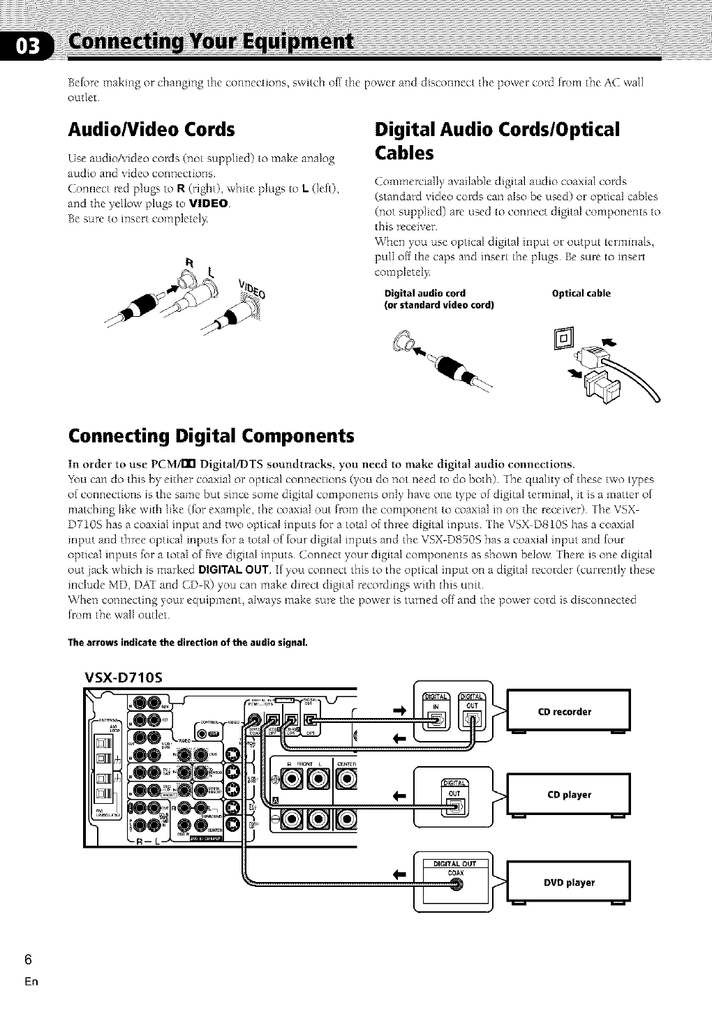
Audio/Video Cords
Use audio/video cords (not supplied) to make analog
audio and video connections
Connect red plugs to R (riglnt), white plugs to L(left),
and the yellow plugs to VIDEO
Be sure to insert completel_
Digital Audio Cords/Optical
Cables
Commercially available digital audio coaxial cords
(standard video cords can also be used) or optical cables
(not supplied) are used to connect digital components to
this receiver
When you use optical digital input or output terminals,
pull o{f fine caps and insert the plugs Be sure to insert
completeIy
Digital audio cord
(or standard video cord
Optical cable
Connecting Digital Components
In order to use PCM/[II Digital!DTS soundtracks, you need to make digital audio colmections,
Ybu can do this by either coaxial or optical connections (you do not need to do both) The quality of these two types
of connections is the same but since some digital components only have one type of digital terminal, it is a matter of
matching like with like (for example, the coaxial out from the component to coaxial in on the receiver) The VSX
D710S has a coaxial input and two optical inputs for a total of three digital inputs The VSX D810S has a coaxial
input and three optical inputs for a total of {our digital inputs and the VSX-D8505 has a coaxial input and {our
optical inputs for a total of five digital inputs Connect your digital components as shown below There is one digital
out jack which is marked DIGITALOUT if you connect this to the optical input on a digitaI recorder (currently these
include MD, DAT and CD R) you can make direct digital recordings with this unit
When connecting your equipment, always make sure the power is turned off and the power cord is disconnected
from the ,,vail outlet
The arrows indicate the direction of the audio signal.
VSX-D710S I
m_ CD recorder I
I
4-
6
En
Connecting Your Equipment
VSX-D850S only
f :=.=.r,I
im m
DVD player i
CD player
CDrecorder
VCR
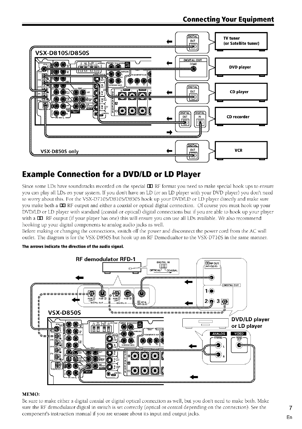
Example Connection for a DVD/LD or LD Player
Since some LDs have soundtracks recoMed on tile special I_ RE {ormat you need to make special hook ups to ensure
you carl play all LDs on your system I[ you don't have an LD (or all LD player with your DVD player) you don't need
to worry about this For tile VSX D710SIDSlOSID850g hook up your DVD/LD or LD player directly and make sure
you make both a I_ RF output and either a coaxial or optical digital connection Of course you t_lust hook up your
DVD/LD or LD player with standard (coaxial o1:optical) digital connections but if you are able to hook up your player
with a I_ RF output (if your player has one) this will ensure you can use all LDs available We also recommend
hooking up your digital components to analog audio jacks as well
Before making or changing the connections, switch off the power and disconnect the power cord (tom the AC wail
outlet The diagram is (or the VSX D8505 but hook up an RF Demodualtor to the VSX D710S in the same manner
The arrows indicate the direction of the audio signal.
VSX-D850S
MEMO:
Be sure to make either a digital coaxial or digital optical connection as well, but you don't need to make both Make
sure the RF demodulator digital in switch is set correctly (optical or coaxial depending on the connection) See the
component's instruction manual if you are unsure about its input and out put jacks
7
En
Connecting Your Equipment
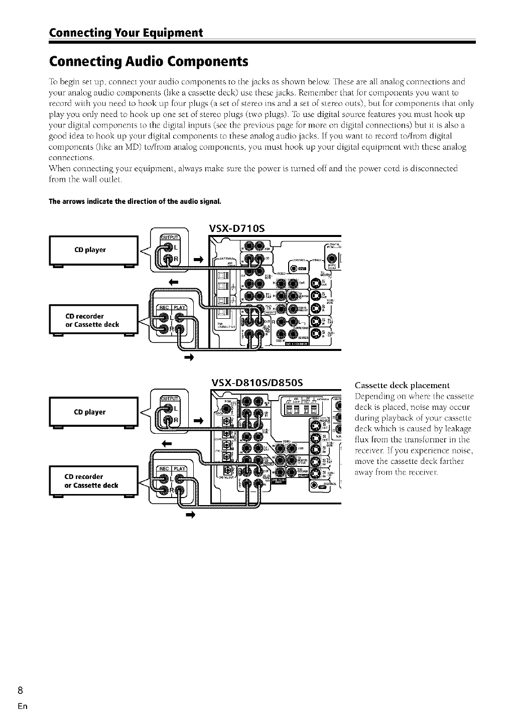
Connecting Audio Components
To begin set up, connect your audio components to tile jacks as shown below These are all analog connections and
your analog audio components (like a cassette deck) use these jacks Remember that for components you want to
record with you need to hook up {our plugs (a set of stereo ins and a set of stereo outs), but {or components that only
play ),ou only need to hook up one set of stereo plugs (two pIugs) _b use digital source {eatures you must hook up
),our digital components to the digital inputs (see the previous page for more on digital connections) but it is also a
good idea to hook up your digital components to these analog audio jacks If you want to record to/{rom digital
components (like an MD) to/flom analog components, you must hook up ),our digital equq?ment with these analog
colM]ectiot]s
When connecting your equipment, always make sure the power is turned off and the power cord is disconnected
fl:om the walI outlet
The arrows indicate the direction of the audio signal.
ImCD player
I CD recorder
or Cassette deck
VSX-D710S
VSX-D810SID850S
I CD player
ICD recorder
or Cassette deck
Cassette deck placement
Depending on where the cassette
deck is placed, noise may occur
during playback of ),our cassette
deck which is caused by leakage
flux flom the trans(ormer in the
receiver If you experience noise,
move the cassette deck farther
away [rom the receiver
8
En
Connecting Your Equipment
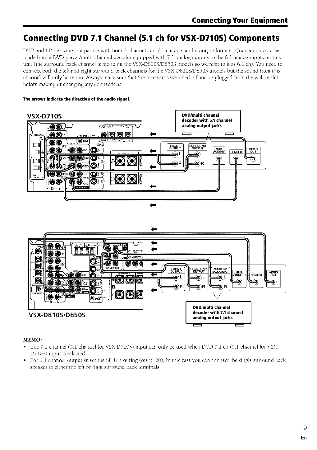
Connecting DVD 7.1 Channel (5.1 ch for VSX-D710S) Components
DVD and LD discs are compatible with both 2 channel and 7 1 channel audio output {ormats Connections call be
made from a DVD player/muhi-cbanneI decoder equipped with 7 1 analog outputs to tile 6 1 analog inputs on this
unit (the surround back cbanneI is mono on the VSX D8105_)8505 models so we refer to it as 6 1 oh) You need to
connect both the left and right surround back channels for the VSX D8105/D8505 models but the sound Irom this
channel will only be mono Always make sure that the receiver is switched off and unplugged from the ,,vailoutlet
before making or changing any connections
The arrows indicate the direction of the audio signal.
VSX-D710S
DVD/multi channel
decoder with 5.1 channel
analog output jacks
4-
4-
VSX-D810S/D850S I DVDImulti channel ]
decoder with 7.1 channel
analog output jacks
VIDEO ]
MEMO:
•The 7 1 channeI (5 1 channel lot VSX DT10S) input can only be used when DVD ?1 ch (5 1 channeI for VSX
DT10S) input is selected
• For 6 1 channel output select the SB lch setting (see p 20) In this case you can connect the single sunound back
speaker to either the left or right surround back teHninals
9
En
Connecting Your Equipment
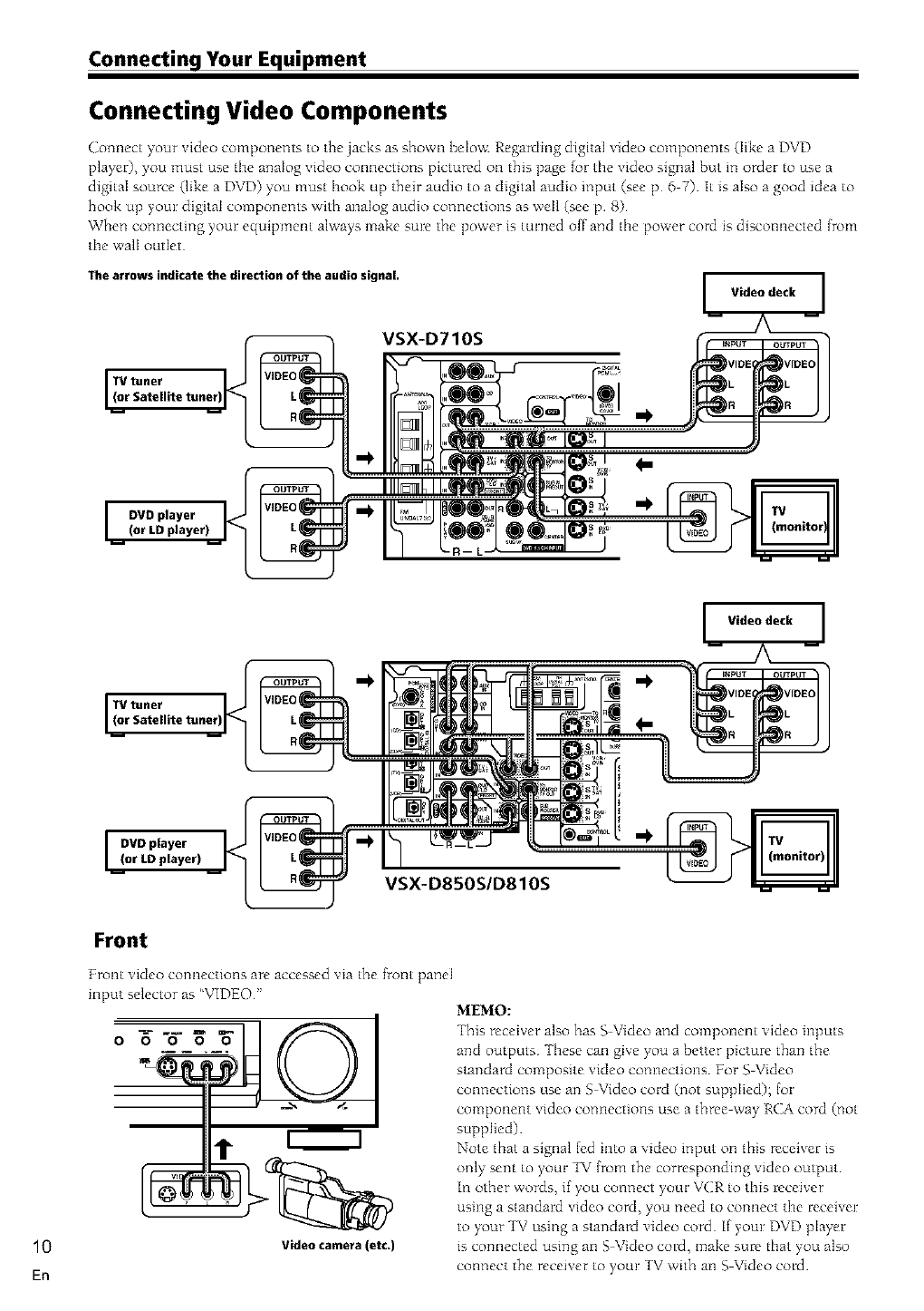
Connecting Video Components
Connect your video components to the jacks as shown belov< Regarding digital video components (Iike a DVD
player), you must use tile analog video connections pictured on this page {or tile video signal but in order to use a
digital source (like a DVD) you must hook up their audio to a digital audio input (see p 6 7) It is aIso a good idea to
hook up your digital components with anaIog audio connections as well (see p 8)
When connecting your equipment always make sure the power is turned off and tIne power cord is disconnected from
tile walI outlet
The arrows indicate the direction of the audio signal.
Video deck
VSX-D710S
10
En
VSX-D850S/D810S
Front
Front video connections are accessed via the _nt panel
input selector as "VIDEO"
1"
Video camera(etc.)
Video deck
MEMO:
This receiver also has S Video and component video inputs
and outputs -fhese can give you a better picture than the
standard composite video connections For S Video
connections use an S Video cord (not supplied); (or
component video connections use a three way RCA cord (not
supplied)
Note that a signal led into a video input on this receiver is
only sent to your TV from the corresponding video output
in other words, if you connect your VCR to this receiver
using a standard video cord, you need to connect the receiver
to your TV using a standard video cord if your DVD player
is connected using an S Video cord, make sure that you also
connect the receiver to your TV with an S Video cord

Connecting Your Equipment
Connecting Antennas
Connect the AM loop antenna and tile FM \_ire antenna as shown below To improve reception and somld quality,
connect external antennas (see Using external antennas, below) AJways make sure that tile receiver is switched off
and unpJugged from the wail outlet be_re making or changing any ¸ connections¸
VSX-D710S VSX-D810S/D850S
AM loop antenna
Assemble the antenna and connect to fine receiver
Attach to a wail, etc (if desired) and face ill the
direction that gi_es tile best reception
FM wire antenna
Connect the FM wire antenna and fuIly extend vertically
along a wmdo\_ frame c_r other suitable area, etc
Antenna snap connectors
Twist the exposed wire strands together and inse_ into
the hole, then snap the connector shut
3/8 in. (10mm)
Using External Antennas
To improve FM reception
Connect an extemaJ FM antenna
75_coaxialcable [., _suJ
ANIB_I_A
VSX-D710S
To improve AM reception
Connect a 15 18 feet length o[ \inyl-coated wire to the AN/i
antenna terminaJ without disconnecting the supphed AM loop
antenna
For the best possible reception, suspend horizontally outdoors
_F L Outdoor antenna
IVidn°yl_:canttelldI:ire) @_J i _ J
11
Kn
Connecting Your Equipment
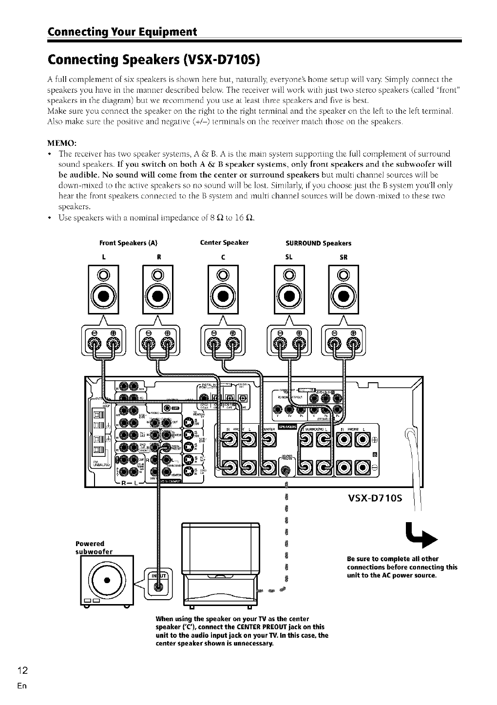
Connecting Speakers (VSX-D710S)
A full complement of six speakers is shown here but, _laturall>, everyo_leg home setup will vat> Simply comlect the
speakers you have ill the manner described below The receiver will work with just two stereo speakers (called 'front"
speakers in the diagram) but we recommend you use at least three speakers and bye is best
Make sure you connect the speaker on tile right to the right terminal and the speaker on the left to the left terminal
Also make sure the positive and negative (+/) terminals on the receiver match those on the speakers
MEMO:
•The receiver has two speaker systems, A £r B A is the main s>stem supporling the full complement of surround
sound speakers If yon switch on both A _ Bspeaker systems, only front speakers and the subwoofer will
be audible. No sound will come from the center or surround speakers but multi channel sources will be
down-mixed to the active speakers so no sound will be lost Similarl> if you choose just the B system you'lI only
hear the front speakers connected to the B system and multi channel sources ,,viiibe down mixed to these two
speakers
• Use speakers,,vith a nominaI impedance of 8 £l to 16 £l
Front Speakers (A) Center Speaker SURROUND Speakers
L R C SL SR
,
When using the speaker on your IV as the center
speaker ('C'), connect the CENTER PREOUT jack on this
unit to the audio input jack on your TV. in this case, the
center speaker shown is unnecessary.
VSX-D710S
Powered
subwoofer
Be sure to complete all other
connections before connecting this
unit to the AC power source.
12
En
Connecting Your Equipment
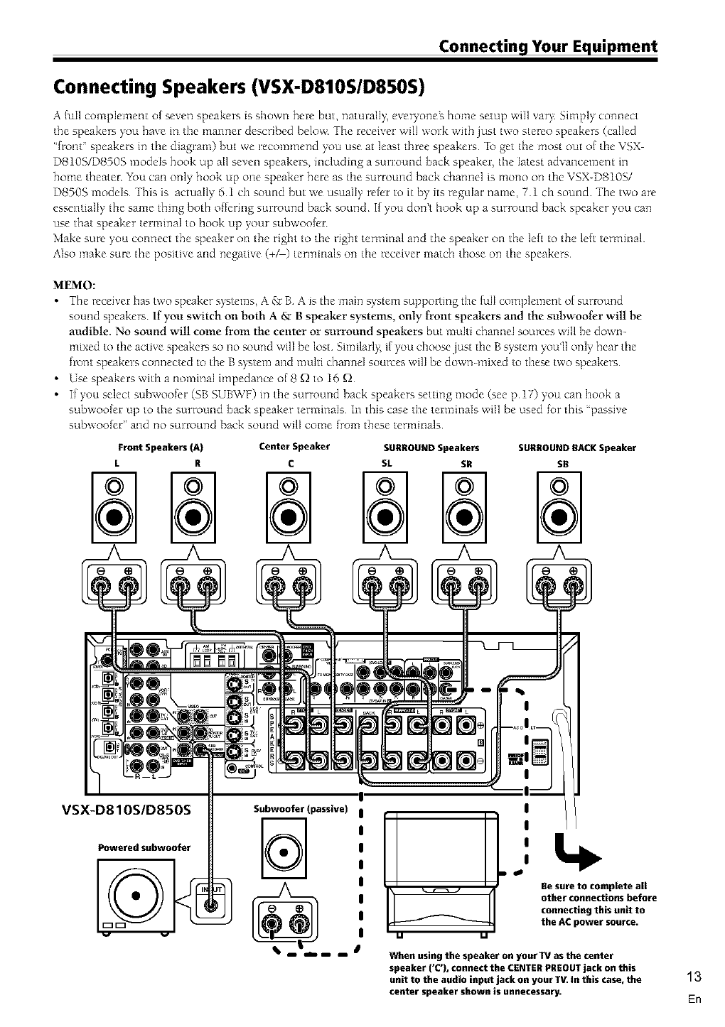
Connecting Speakers (VSX-D810S/D850S)
A {oil complement of seven speakers is shown here but, namrally, everyoneZ home setup will vary: Simply connect
the speakers you have in tile manner described below The receiver will work with just two stereo speakers (called
"{rout" speakers in the diagram) but we recommend you use at least three speakers To get the most out of tile VSX
D810S/D8503 models hook up all seven speakers, including a surround back speaker, the latest advancement in
home theater _k_u can only hook up one speaker here as the surround back channel is mono on the VSX-D810S/
D8503 models This is actually 51 ch sound but we usually refer to it by its regular name, 71 ch sound The two are
essentially the same thing both o{fering surround back sound If ),ou dont hook up a surround back speaker you can
use that speaker terminal to hook up your fubwoo{er
Make sure you connect the speaker on the right to the right terminal and the speaker on the leb to the leb terminal
Also make sure the positive and negative (+_) terminals on the receiver match those on the speakers
MEMO:
•_hemc_iverhastwosP_akersystems_A&BAisthemai_1s`jstemsu_P_rtmgtheIu_c_mP_ement_fsurr_u_1d
sound speakers If you switch Ollboth A 6,_B speaker systems, only front speakers and the subwoofer will be
audible. No sound will come fl'om the center or surround speakers but multi channel sources will be down-
mixed to the active speakers so no sound will be lost Similarly, if you choose just the B system ),%_u'llonly hear the
front speakers connected to the B system and multi channd sources will be down-mixed to these two speaker-;
•Use speakers with a nominaI impedance of 8 f_ to 16 f_
• If you select subwoofcr (SB SUB'vVF)in the surround back speakers setting mode (see p 17) you can hook a
subwoo{er up to the surround back speaker terminals In this case the terminals will be used for this 'passive
subwoo{er" and no surround back sound wilI come {tom these terminals
FrontSpeakers{A) CenterSpeaker SURROUNDSpeakers SURROUNDRACKSpeaker
LRCSL SR SR
VSX-D810S/D850S
Poweredsubwoofer
Subwoofer (passive)
uIJ
!
!
!
Be sure to complete all
other connectionsbefore
connectingthis unit to
the ACpower source.
When using the speaker on your IV as the center
speaker ('C'), connect the CENTER PREOUT jack on this
unit to the audio input jack on your TV. In this case, the
center speaker shown is unnecessary.
13
En
Connecting Your Equipment
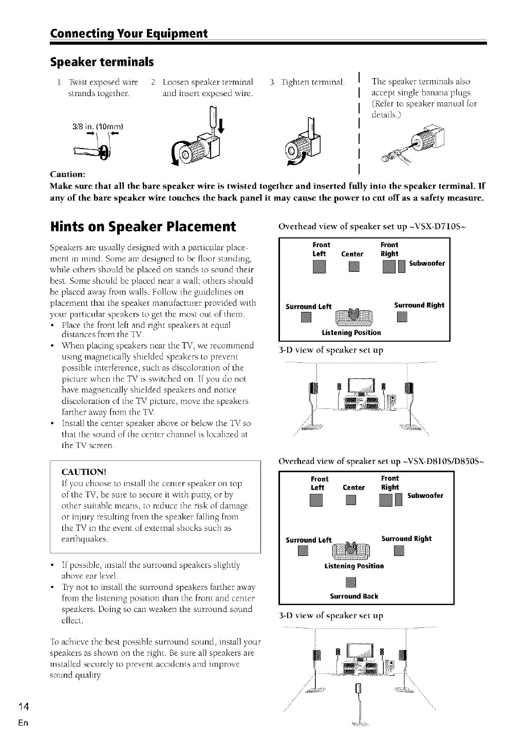
Speaker terminals
1 Twist exposed wire
strands together
3/8 in. (lOmm}
Caution:
2 loosen speaker termmaI 3 Tighten terminal
and insert exposed wil_
The speaker terminals also
accept single banana plugs
(Refer to speaker manual {or
details)
Make sure that all the bare speaker wire is twisted together and inserted fully into the speaker terminal. If
any of the bare speaker wire touches the back panel it may cause the power to cut off as a safety measure.
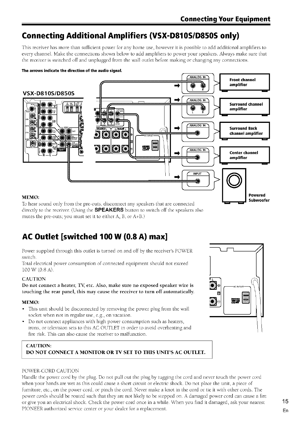
Hints on Speaker Placement
Speakers are usually designed with a particular place
ment ill mind Some are designed to be floor standing,
while others should be placed on stands to sound their
best Some should be placed near a wail; others should
be placed away flom walls Follow tile guidelines on
placement that the speaker manufacturer provided with
),our particuIar speakers to get the most out of them
•Place the {font left and right speakers at equal
distances from the TV
• When placing speaker_ near the TV, we recommend
using magnetically shielded speakers to prevent
possible interference, sucln as discoloration of the
picture when fine TV is switched on I[ you do not
have magnetically shielded speakers and notice
discoloration of the TV picture, move the speakers
farther away from the TV
Install the center speaker above or below the TV so
that the sound of the center chamleI is localized at
tlne TV screen
CAUTION[
if you choose to install the center speaker on top
of the TV, be sure to secure it with putt),, or by
other suitable means, to reduce the risk of damage
or iNury resuhmg flom the speaker failing from
the TV in the event of external shocks such as
earthquakes
If possible, mstalI the surround speakers slightly
above ear level
•_?y not to install the surround speakers {arther away
from the listening position than the {ront and center
speakers Doing so can weaken the surround sound
effect
To achieve the best possible surround sound, install your
speakers as shown on the right Be sure all speakers are
installed securely to prevent accidents and improve
sound qualit),
Overhead view of speaker set up ~VSX-D710S~
Front Front
Left Center Right
[] _ Subwoofer
SurroundLeft SurroundRight
ListeningPosition
3-D view of speaker set up
Overhead view of speaker set up ~VSX-D810S/D850S~
Front Front
Left Center Right
_Subwoofer
SurroundLeft SurroundRight
ListeningPosition
SurroundBack
3-D view of speaker set up
14
En
Connecting Your Equipment
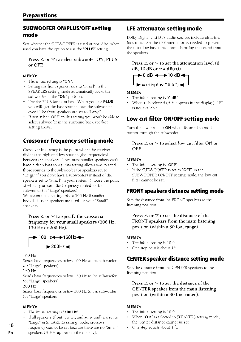
Connecting Additional Amplifiers (VSX-D810S/D850S only)
This receiver has more than sufhcient power {or any home use, however it is possible to add additional amplifiers to
every channel Make the connections shown below to add amplifiers to power your speakers Always make sure that
the receiver is switched off and unplugged from tile wail outlet before making or changing any connections
The arrows indicate the direction of the audio signal.
VSX-D810S/D850S - q " YT ll urro,,ndc,,an,,e,i
oo il _i
•-- •amplifier
Lampl'f'er __l
_b hear sound onI_ from the pre-outs, disconnect any' speakers that are connected
directly to the receiver (Using the SPEARERS button to switch offthe speakers also
mutes the pre-outs; you must set it to either A, B, or A+B)
AC Outlet [switched 100 W (0.8 A) max]
Power supplied through this outlet is turned on and off by the receiver's POWER
switch
7btaI electrical power consmnption of connected equipment should not exceed
100 W (08 A)
CAUTION
Do not connect a heater, TV, etc, Also, make sure no exposed speaker wire is
touching the rear panel, this may cause the receiver to turn off"automatically:
MEMO:
•This unit should be disconnected by removing the power plug flom the ,,vail
socket when not in regular use, eg, on vacation
•Do not connect appliances with high power consumption such as heaters,
irons, or television sets to this AC OUTLET in order to avoid overheating and
fire risk This can also cause the receiver to malfunction
CAUTION:
DO NOT CONNECT AMONITOR OR "IV SET TO THIS UNIT'S AC OUTLET.
POWER-CORD CAUTION
Handle the power cord by the plug Do not pull out the plug by tugging the cord and never touch the power cord
when your hands are wet as this could cause a short circuit or electric shock Do not place the unit, a piece of
furniture, etc, on the power cord, or pinch the cord Never make a knot m the cord or tie it with other cords The
power cords should be routed such that they are not likely to be stepped on A damaged power cord can cause a fire
or give you an electrical shock Check the power cord once in a while When you find it damaged, ask your nearest
PIONEER authorized service center or your dealer for a Beplacement
15
En

16
En
Setting Up for Surround Sound
Be sure to switch the power of this unit on (The
STANDBY indicator goes out)¸
To ensure the best possible surround sound, be sure to
complete the _IIowing set up operations¸ This is
particularly important when using the _ (Dolby)/DTS
surround mode¸ You only need to make these settings
once (unless you change the placement of your current
speaker system or add new speakers, etc) Refer to the
_lIowing pages _r detailed descriptions of the settings
available for each mode
11
2- Q) (X) (E)
(;) (D _':) (?3
4_e
1 Press RECEIVER to turn the power on.
The STANDBY indicator goes out
2 Press RCV
This button switches the remote to the mceiver_
surround setup mode
3 Press < or t> to select the mode you want to
set
For best results, start with 'SPEAKERS setting mode"
and make your initial adlustments m the order
described below
The current settings are displayed automatically:
• DTS-ES ON/OFF setting mode (page 17) (VSX
D810S/D850S only)
Use to mm the DTS-ES (surround back) channels
• SPEAKERS (Front, Center, Surround) setting
mode (page 17)
Use to specif), the size and type of speakers you have
connected
• SPEAKERS (Surround Back) setting mode (page
17) (VSX-D810S/D850S only)
Use to specif_ the size and type of surround back
speaker you have connected or if you have con
nected a subwoofcr here
• SUBWOOFER ON/PLUS/OFF setting mode (page 18)
Use to specff), if the subwoofcr is set to on, plus or off
• Crossover frequency setting mode (page 18)
Use to determine which [rcquencies will be sent to
the subwoofer (m""hrge" speakers if you dont have
a subwoolc0
• LFE attenuator setting mode (page 18)
Use to specif), the peak level lor the LFE channel and
the crossover network lot rerouted bass lrcquencies
• Low cut filter ON/OFF setting mode (page 18)
Use to cut the distorted sound from the subwooIcr
• FRONT speakers distance setting mode (page 18)
Use to specif), the distance from your listening
position to your fiont speaker
• CENTER speakers distance setting mode (page 18)
Use to specif), the distance {tom your listening
position to your center speaker
• SURROUND speakers distance setting mode (page
19)
Use to specif), the distance from your listening
position to your surround speakers
• SURROUND BACK speakers distance setting
mode (VSX-D810S/D850S only) (page 19)
Use to specif), the distance from your listening
position to your surround back speaker
• Dynamic range control setting mode (page 19)
Use to compress the dynamic cmlge of the sound track
• Dual mono setting mode (page 19)
Use with [112Digital software that has dual mono
encoding if you want to isolate one channel m listen
m this specialized mono mode
• Component input 1 setting (page 20)
Use to specif), the video component connected to this
mput
• Component input 2 setting (page 20)
Use to specif), the video component connected to this
input
• Multi Channel External Decoder Surround Back
lch/2ch setting (VSX D810S/D850S only-) (page 20)
Use to specif), whether you hooked up your External
Multi Channel Decoder surround back speaker
connection with one or two cords If you're not using
a External Multi Channel Decoder ignore this setting
• Coaxial digital input setting (page 20)
Use to speci[), the input to be assigned to the coaxial
digital input
• Optical digital input 1 setting (page 20)
Use to specif), the input assigned to this optical digital
mput
• Optical digital input 2 setting (page 20)
Use to specif), the input assigned to this optical digital
mput
• Optical digital input 3 setting (VSX-D810S/D850S
only) (page 20)
Use to specif), the input assigned to this optical digital
mput
• Optical digital input 4 setting (VSX-D850S only)
(page 21)
Use to specif), the input assigned to this optical digital
mput
4 Press _. or V to select the setting you want.
The setting is entered automatically
5 Repeat steps 3 and 4 to set other surround
modes
MEMO:
Press ENTER to exit the setting mode
The setting mode is automatically exited if no operation
is performed within 20 seconds

Preparations
DTS-ES ON/OFF setting mode (VSX-
D810S/D850S only)
This setting allows you to hear surround back cbannels
on D_S disc regardless of whether the disc itself is a 51
Ch disc or a 61 Ch disc Naturally you need to hook up
sunound back speakers (see p 13) and set them properly
(see below on this page) in order to hear surround back
channels If you choose ON you will Inear surround back
chamds with DIS discs If _u choo_ OFF you will not
Choose DTS-ES ON or OFF by using the A
or _' buttons.
MEMO:
If you choose none k_r the surround back speakers setting
tater on this page you won't be able to select ON here
•You'll only get surround back channel sound when
die receiver is m STANDARD mode (see p 27 29),
DTS ES is set to ON and the disc is a DTS 5 1/6 1
channel disc
SPEAKERS (Front, Center, Surround)
setting mode
This setting establishes the size and configuration of the
speaker system you have connected So, for example,
here you set whether you have connected surround
speaker-_ or not, and bow big they are Selecting 'Large"
or 'Small" will determine how much bass is sent by the
receiver to the speakers being set
In the displa> "F", "C", and "S" refer to lrom, center,
and surrcmnd speakers respectively Speaker size is
denoted as 'L" tot lalge speakers, 'S" for small
speaker% and ' :_" (asterisk) if no speaker is connected
Choose a speaker setting mode according to
the speakers you hooked up. Use the A or V
buttons.
The configm:ations shown below will appear in the
display on the fi:ont of the receiver One of them
should match your speaker set up Cycle through the
diffcrem possibilities until you find the one that
matches your set up
Press t:> to advance to tI3e next receiver setting, and
press <a to return to a previous receiver setting¸
IFL-EL-SL t [FS-E_-SS
IFL-CL- S t
It [FS-ES-S_
IFL-EL-S_ _ t
t [FS-ES-SS
[FL-ES-SL _ t
{, t [FL-EI-SS
IFL-CS-35 t
t[FL-EI -SL
IFL-CS- S,It]
MEMO:
Ktbe cone size (diameter) of the speaker is larger than 9
inches, please set to Large
SPEAKERS (Surround Back) setting
mode (VSX-D810S/D850S only)
This setting establishes the size of the speaker connected
to the surround back terminal (VSX D810S/D8505 only)
_bu can choose a surround back speaker and its size or
you can choose to hook a subwoo{cr to this terminal
Switch the surround back speaker setting
mode according to the size of the speaker
you hooked up. Use the A or '7 buttons.
The configurations shown below will appear in the
display on the [rout of the receiver Choose one
Cycle through die different possibilities umfl you [md
the one that matches your set up
I[ you select SB SUBWF here you can hook a
subwoofer up to the surround back speaker terminals
(see p13) In this case the terminals will be used for
this 'passive subwooIer" and no surr,nund back
sound will come [tom these terminals
Press t::>to advance to d_e next receiver setting, and
press < to return to a pre'_ious receiver setting
S]_ L IS]] SU]_}4F
It It
MEMO:
•You can only set the surround back speaker to large if
the surround speakers are set to small
•I[ you choose none k/r surround speakers (see
previous setup) you wont be able to select any
surr,Jund back speakers either
• 1[ you choose A+B speaker systems no sound is heard
lrom the 'passive subwooler"
17
En
Preparations
SUBWOOFER ON/PLUS/OFF setting
mode
Sets whether tile SUBWOOFER is used or not Also, when
u_d )+_uhave tile option to use tile "PLUS" setting
Press a or Vto select subwoofer ON, PLUS
or OFE
MEMO:
•The initial settingis 'ON"
Setting tile flont speaker size to "Small" in the
SPEAKERS setting mode automatically locks tile
subwoofcr ill the "ON' position
•Use the PLUS for extra bass When you use PLUS
you will get tile bass sounds fiom tile subwoofm
even if the front speakers are set to 'Large"
If you select 'OFF" in this setting you wont be able to
select subwoofer in the surround back speaker
setting above
Crossover frequency setting mode
Crossover frrquency is the point where the receiver
divides the high and low sounds (the lrequencies)
between the speakers Since most smaller speakers can't
handle deep bass tones, this setting allows you to send
those sounds to the subwoofer (or speakers set to
"hrge" if you dont have a subwoofer) instead of the
speakers set to 'Small" m your system Choose the point
at which you want the frequency routed to the
subwoo[er (or 'Large" speakers)
We recommend setting this to 200 Hz if smaller
booksheff-type speakers are used for your 'Small"
speakers
LFE attenuator setting mode
Dolby Digital and DTS audio sources include uhra low
bass tones Set the LFE attenuator as needed to prevent
the uhra low bass tones fiom distorting the sound [rom
the speakers
Press A or V to set the attenuation level (0
dB, 10 dB or ** dB(_,)).
(display "_ _")_
MEMO:
• The initial setting is "0 dB"
• When _ is selected (* * appears m the display), LFg
is not available
Low cut filter ON/OFF setting mode
Turn the 1o\_cut filte_ ON \_hen distorted sound is
output throu_ the subwoo_r
Press A or 'V'to select low cut filter ON or
OFE
MEMO:
•_he initial setting is 'OFF
•If the SUB\VOOFER is set to 'OFF' in the
SUBWOOFER ON/OFF setting mode, the low cut
filter cannot be set
FRONT speakers distance setting mode
Setsthe distance _m the FRONT speakersto the
listening position
Press A or 'V to specify the crossover
frequency for your small speakers (100 Hz,
150 Hz or 200 Hz).
Press A or V to set the distance of the
FRONT speakers from the main listening
position (within a 30 foot range).
[--_100 Hz<_II_ 150Hz_I-]
1_200Hz_l J
100 Hz
Sends bass fl:equencies below 100 Hz to the subwoofcr
(or 'hrge" speakers)
150 Hz
Sends bass fi:equencies below 150 Hz to the subwoofcr
(or 'Large" speakers)
200 Hz
Sends bass fi:equencies below 200 Hz to the subwoofcr
(or 'Large" speakers)
MEMO:
• The initial settingis 10 ff
• One step equals about lh
CENTER speaker distance setting mode
Setsthe distance _m the (]ENTER speakers to the
listening position
Press A or V to set the distance of the
CENTER speaker from the main listening
position (within a 30 foot range)
18
En
MEMO:
•The initial setting is '100Hz"
If all speakers (lrom, center, and surround) are set to
"Large" m SPEAKERS setting mode, crossover
frequency cannot be set because there are no 'Small"
speakers (* * * appears in the display)
MEMO:
• The initial setting is 10 {t
• When 'C:_"is selected in SPEAKERS setting mode,
the Center distance cannot be set
• One step equals about 1 ff
Preparations
SURROUND speakers distance
setting mode
Use to set the SURROUND speakers distance Like tile
(;ENTER speaker position, tile SURROUND speakers
may be set in a location closer or farther to your main
listening position than the FRONT speaker-; Set tile
distance of tile SURROUND speakers accurately to heal:
sounds coining from botll FRONT and SURROUND
speaker-; at the same time
Dynamic range control setting mode
Dynamic range is tile difference between tile loudest and
softest sounds in any given signal Tile dynamic range
control helps you play back sounds so tile quieter sounds
are audible yet tile louder sounds don't get distorted It
does this by compressing the dynamic range When
watching a movie at low volume, setting this function
enables low level sounds to be heard more easily but you
won't be jolted by louder sounds
Press A or _' to set the distance of the
SURROUND speakers fl'om the main
listening position (within a 30 foot range).
MEMO:
•The initial setting is 10 ft
•When "S:_" is selected in SPEAKERS setting mode,
the SURROUND distance cannot be set
• One step equals about 1 ft
Press A or _' to set the dynamic range control
(OFE MAX, or MID)
MEMO:
• The initial setting is "OFF"
• When the volume level is increased, set to OFE
•For listening enjoyment at low volumes, set to 'MAX"
for maximum dynamic range compression
• Dynamic range control is eflecdve only when a Dolby
Digital signal is being played back
SURROUND BACK speaker distance
setting mode (VSX-D810S/D850S
only)
Use to set the SURROUND back speaker distance |lke
the SURROUND speakers, the SURROUND BACK
speakers ITlaybe set in a location closer or farther to
your mare bstenmg position1 than the FRONT speakers
Set the distance of the SURROUND speakers accurately
to hear sounds coming from both FRONT and
SURROUND speakers at the same time
Press A or Vto set the distance of the
SURROUND speakers fl'om the main
listening position (within a 30 foot range).
MEMO:
• The mitiaI setting is 10 ft
•When "SB*" is selected in SPEAKERSsetting mode,
the SURROUND BACK distance cannot be set
• One step equals about 1 ft
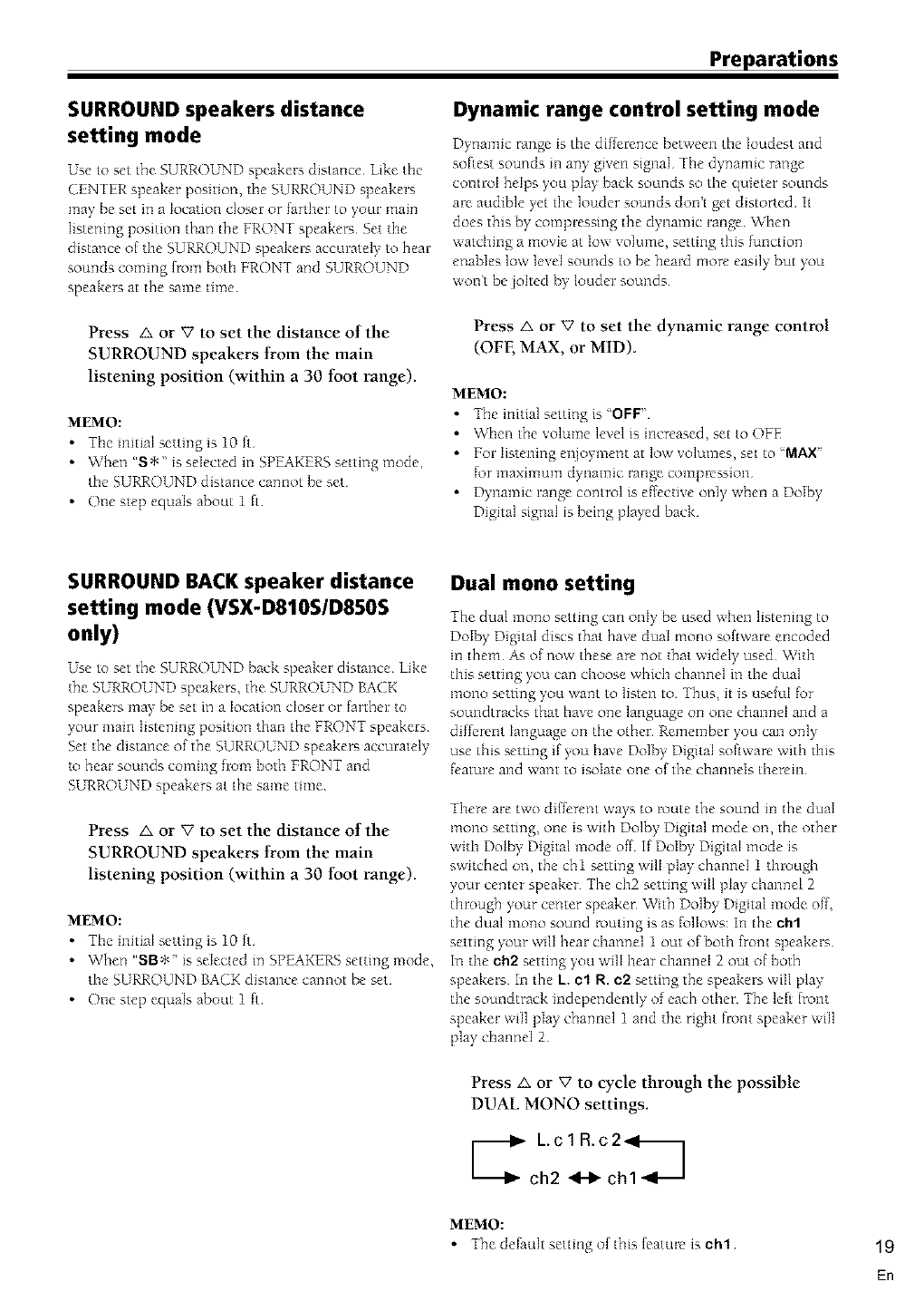
Dual mono setting
The dual mono setting can only be used when listening to
Dolby Digital discs that have dual mono software encoded
in them As of now these are not that widely used With
this setting you can choose which channel in the dual
mono setting you want to listen to Thus, it is use{uI for
soundtracks that have one language on one channel and a
different language on the other Remember you can only
use this setting if you have Dolby Digital software with this
feature and want to isolate one of the channels therein
There are two diIferent ways to route the sound in the dual
mono setting, one is with Dolby Digital mode on, the other
with Dolby Digital mode off If Dolby Digital mode is
switched on, the chl setting will play channel 1 through
your center speaker The ch2 setting will play channel 2
through your center speaker With Dolby Digital mode off,
the dual mono sound routing is as follows: in the ehl
setting your will hear channel 1 out of both front speakers
In the eh2 setting you will hear channel 2 out of both
speakers In the k. el R. e2 setting the speakers will play
the soundtrack independently of each other The left {runt
speaker will play channel 1 and the right front speaker will
play channel 2
Press A or _' to cycle through the possible
DUAL MONO settings.
,. L.c 1R.c2_l_
ch2 _ chl
MEMO:
• The default setting of this leatme is oh1 19
En
Preparations
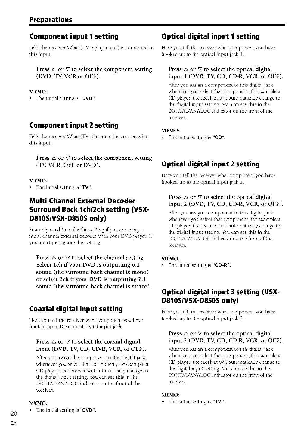
Component input I setting Optical digital input I setting
Tells the receiver What (DVD player, etc) is connected to Here you tell tile receiver what component you have
this input hooked up to tile optical input jack 1
Press _. or Vto select the component setting
(DVD, TV, VCR or OFF).
MEMO:
•The initial setting is "DVD"
Component input 2 setting
Tells the receiver What (T_ player etc) is connected to
tInis input
Press _. or V to select the optical digital
input 1 (DVD, TV, CD, CD-R, VCR, or OFF)
After you assign a component to this digital jack
whenever you select that compo_ent, for example a
CD player, the receiver will automatically change to
the digital input setting You can see this m the
DIGITAL/ANALOG indicator on the {tom of the
receiver
MEMO:
• The initial setting is "OD".
Press A or Vto select the component setting
(TV, VCR, OFF or DVD).
MEMO:
• The initial setting is "TV"
Multi Channel External Decoder
Surround Back lch/2ch setting (VSX-
D810S/VSX-D850S only)
Ybu o_lly need to make this setting if you are using a
multi channel external decoder with your DVD player If
)+ou arent just ignore this setting
Optical digital input 2 setting
Here you tell the receiver what componem you have
hooked up to the optical input jack 2
Press _. or V to select the optical digital
input 2 (DVD, TV, CD, CD-R, VCR, or OFF)
After you assign a component to this digital jack
whenever you select that componem, for example a
CD pIayer, the receiver will automatically change to
the digital input setting You can see this m the
DIGITAL/ANALOG indicator on the {tom of the
receiver
2O
Press A or V to select the channel setting
Select lch if your DVD is outputting 6 1
sound (the surround back channel is mono)
or select 2ch if your DVD is outputting 7.1
sound (the surround back channel is stereo).
Coaxial digital input setting
Here you tell the receiver what componem you have
hooked up to the coaxial digital input jack
Press A or V to select the coaxial digital
input (DVD, TV, CD, CD-R, VCR, or OFF).
After you assign the component to this digital jack
whenever you select that compo_ent, for example a
CD player, the receiver will automatically change to
the digital input setting You can see this in the
DIGITAIJANALOG indicator on the front of the
receiver
MEMO:
• The initial setting is "DVD".
MEMO:
• The initial setting is "CD-R".
Optical digital input 3 setting (VSX-
D810S/VSX-D850S only)
Here you tell the receiver what componem you have
hooked up to the optical input jack 3
Press _. or V to select the optical digital
input 2 (DVD, TV, CD, CD-R, VCR, or OFF)
After you assign a component to this digital jack,
whenever you select that componem, for example a
CD pIayer, the receiver will automatically change to
the digital input setting You can see this m the
DIGITAL/ANALOG indicator on the {tom of the
receiver
MEMO:
• The initial setting is "TV'.
En
Optical digital input 4 setting (VSX-
D850S only)
Here you tell the receiver \vlnat component you have
Press _, or V to select the optical digital
input 2 (DVD, TV, CD, CD-R, VCR, or OFF).
Alter you assign a component to this digital jack
whenever you select that component, for example a
CD player, tile receiver ,,viii automatically change to
tile digital input setting Yk_ucan see this ill the
DIGITAUANALOG mdicator on the {rout of the
receiver
MEMO:
•The initial setting is "VOR"
• The digital out signal corresponds to the selected
input function (for example, DVD)
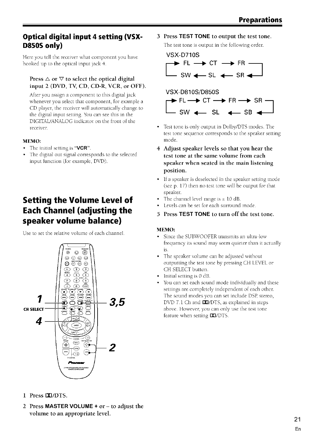
Setting the Volume Level of
Each Channel (adjusting the
speaker volume balance)
Use to set the relative xolume of each channel
® ©®
@®@@
3,5
c. S_LEClr II _rL ClILE_ I_ T_
--2
Preparations
Press TEST TONE to output the test tone.
The test tone is output m the fdlowmg order
VSX-D710S
UFL"_I_CT "_1_ FR A
SW _ SL _ SR
4
5
VSX-D810S/D850S
C L"_I_CT"_II,.FR"_I_ SRq
SW _ SL <._SB
lest tone is only output in Dolby/DTS modes The
test tone sequence corresponds to the speaker setting
mode
Adjust speaker levels so that you hear the
test tone at the same volume from each
speaker when seated in the main listening
position
I[ a speaker is deselected in the speaker setting mode
(see p 17) then no test tone will be output for that
speaker
The channel level range is + 10 dB
Levels can be set tot each surround mode
Press TEST TONE to turn off the test tone.
MEMO:
• Since the SUBWOOFER transmits an ultra low
frequency its sound may seem quieter than it actually
is
• The speaker volume can be adjusted without
outputting the test tone by pressmg CH LEVEL or
CH SELECT button
• Initial setting is 0 dB
•You can set each sound mode individually and these
settings are completely independent of each other:
The sound modes you can set mclude DSP stereo,
DVD 7 1 Ch and rlrl/DTS as explained in steps
above However, you can only use the test tone
Jeature when setting DrI/DTS
1 Press Nrl/DTS.
2 Press MASTER VOLUME + or- to adjust the
volume to an appropriate level. 21
En
22
En
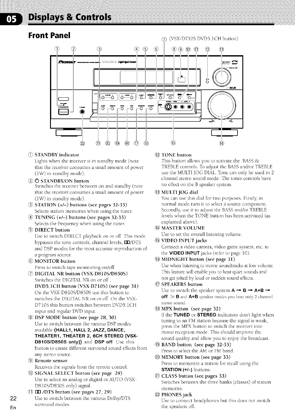
Front Panel
m
(1) STANDBY indicator
lights when tile receiver is in standby mode (note
that the receiver consumes a small amount of power
(1W) in standby mode)
_2) O STANDBY/ON button
Switches the receiver between on and standby (note
that the receiver consumes a small amount of power
(1W) in standby mode)
(3_ STATION (+/-) buttons (see pages 32-33)
Selects station memories when using the tuner
@ TUNING (+/-) buttons (see pages 32-33)
Selects the [rcquency when using the tuner
_5) DIRECT button
Use to switch DIRECT playback on or off This mode
bypasses the tone controls_ channel levels, [KI/DTS
and DSP modes lot the most accurate reproduction of
a prograltq source
(6) MONITOR button
Press to switch tape monitoring on/oil
(7_ DIGITAL NR button (VSX D810S/D850S)
Switches the DIGITAL NR on or off
DVDS.1CH button (VSX D710S) (see page 31)
On tlne VSX D810S/D850S use this button to
switches the DIGITAL NR on or off On the VSX
D710S this button switches between DVD5 1CH
input and regular DVD input
@ DSP MODE button (see page 28, 30)
Use to switch between the various DSP modes
available (HALL1, HALL 2, JAZZ, DANCE,
THEATER1, THEATER 2, 6OH STEREO [VSX-
D810S/D850S only]) and DSP off Use this
button to create different surround sound ef[ects from
any stereo source
[9) Remote sensor
Receives the signals fiom the remote control
(i0)SIGNAL SELECT button (see page 29)
Use to select an analog or digital or AUTO (VSX
D810SID850S only) signal
(11)I_/DTS button (see pages 27, 29)
Use to switch between the various Dolb],/DTS
surround I]]odes
(VSX DT10S DVD5 1CH button)
hF )) ,
I
c'l
'iZ TONE button
This button allows you to activate the BASS _r
TREBLE controls To adlust the BASS and/or TREBLE
use the MUVfI lOG DIAL Tone can only be used in 2
channel stereo sound mode The tones controls have
no effect on the B speaker system
(1a_MULTI JOG dial
Y\)u can use this dial for two purposes Yirstl> m
norltla] mode [urn it to select a source colt]portent
SecondI 5 use it to adlust the BASSand/or TREBLE
levels when the TONE button has been activated (as
explained above)
(14)MASTER VOLUME
Use to set the overaI1 listening volume
_ VIDEO INPUT jacks
Connect a video camera, video game system, etc to
the VIDEO INPUTjacks (refer to page 10)
1_ MIDNIGHT button (see page 31)
Use when listening to movie _)undtracks at low volume
This {_'aturewill enable you to bear quiet som_ds and
not get jolted by loud or sudden sound effects
(17)SPEAKERS button
Use to switch the speaker system A _ B _ A+B
off In Band A+B speake_modes you hear only 2 channel
stelco sound
(18 MPX button (see page 32)
l[ the TUNED or STEREO indicators don't light when
tuning to an FM station because the signal is weak,
press the MPX button to switch the receiver into
mono reception mode This should improve the
sound quality and allow you to enjoy the broadcast
(19)BAND button (see page 32_33)
Press to select the AM or FM band
2g MEMORY button (see page 33)
Press to memorize a station [or recall using the
STATION (+/-) buttons
'21)CLASS button (see pages 33)
Switches between the three banks (classes) of station
171elTlories
9_ PHONES jack
Use to connect headphones but this does not switch
the speakers of[
Displays & Controls
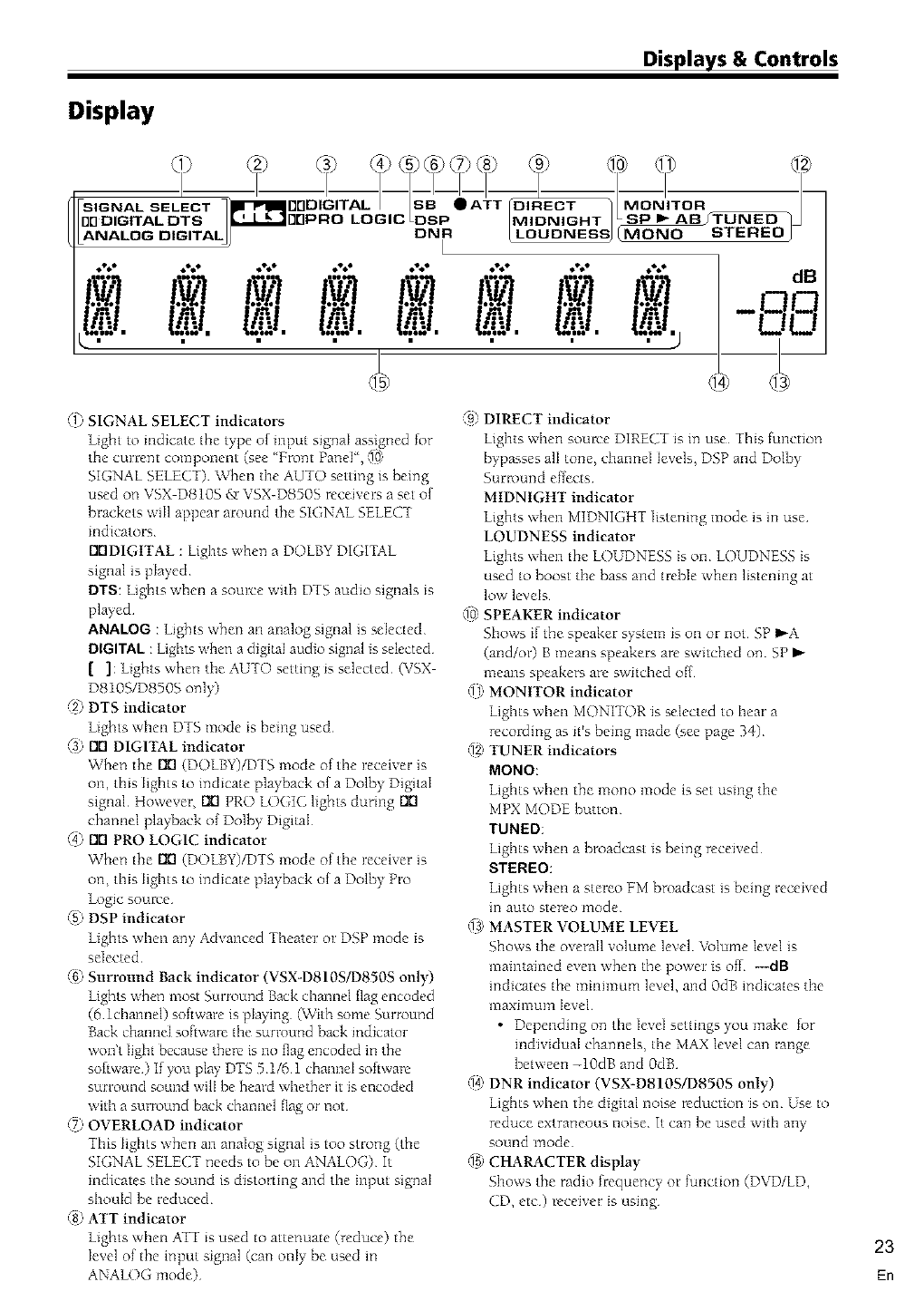
Display
- I- I I-I-
SIGNAL SELECT _-P"II_DDDIGITAL I_ • OlR_RECT _/MONITOR J
ANALOG OIGITAL_ /LUUUNI _JI MUDdU ;_ I I::::H_u J
._*_ _,,,_* ,D_'_,o _,_*_d, oo_Q o_Q • _%*o _,Q_,
l I.L I. l I.
dB
-,q,q
L_L.
_1_SIGNAL SELECT indicators
SIGNAL SELECT) When the AUTO setting is being
used on VSX DS10S gr VSX-D850S receivers a set of
brackets will appear around the SIGNAL SELECT
indicators
EKIDIGITAL : Liglnts when a DOLBY DIGITAL
signal is played
DTS: Liglnts when a source witln DTS audio signals is
played
ANALOG : Lights when an analog signal is selected
DIGITAL: Lights when a dig_taIaudio signal is selected
[ ]: Lights when tlne AUTO setting is selected (VSX
D810S/D850S only)
_2)DTS indicator
L_ghts when DTS mode is being used
(3_ EKIDIGITAL indicator
When the EKI(DOLBY)/DTS mode of tlne receiver is
on, tlnis Iiglnts to indicate playback of a Dolby Digital
signal However, EKIPRO LOGIC lights during I_
channel playback of Dolby Digital
@ EKIPRO LOGIC indicator
When the EKI(DOIBY)/DTS mode of the receiver is
on, this lights to indicate playback of a Dolby Pro
logic soulve
_5)DSP indicator
L_ghts when any Advanced Theater or DSP mode is
selected
(_) Surround Back indicator (VSX-D810S/D850S only)
|lgbts when most Surroui_d Back channel flag encoded
(6 lchannel) software is playing (With some Surrout_d
Back channel software the surro_t_d back indicator
won't light because there is no flag encoded in the
software) If you play DTS 51/6 1 channel software
surround sound wilI be heard whether it is encoded
with a surro_t_d back channel flag or not
(7_OVERLOAD indicator
This lights when an analog signal is too strong (the
SIGNAL SELECT needs to be on ANALOG) It
indicates the sound is distorting and the input signal
should be reduced
@ ATT indicator
Lights when ATT is used to attenuate (reduce) the
level of the input signal (can only be used in
ANALOG mode)
,_91DIRECT indicator
Lights when source DIRECT is in use This functiot_
bypasses alI tone, clnanneI levels, DSP and Dolby
Surround effects
MIDNIGHT indicator
Lights wlnen MIDNIGHT listening mode is in use
LOUDNESS indicator
Lights when the LOUDNESS is on LOUDNESS is
used to boost the bass and treble when listening at
low levels
(10)SPEAKER indicator
Shows if the speaker system is on or not SP I,_A
(and/or) B means speakers are switched on SP
means speakers are switched ofl
(11_MONITOR indicator
Lights when MONITOR is selected to hear a
recording as it's being made (see page 34)
'12_TUNER indicators
MONO:
Lights when the mo_o mode is set using the
MPX MODE button
TUNED:
Lights when a broadcast is being received
STEREO:
Lights when a stereo PM broadcast is being recei ed
in auto stereo mode
(la_MASTER VOLUME LEVEL
Shows the overall volume level _v\)lumelevel is
maintained even when the power is of_ ---dB
indicates the minimum level, and 0dB indicates the
maximum level
• Depending on the level settings you make for
individual channels, the MAX level can range
between -10dB and 0dB
34) DNR indicator (VSX-D810S/D850S only)
Lights when the digital noise reduction is on Use to
reduce extraneous noise It can be used with any
sound mode
_ CHARACTER display
Shows the radio frequency or function (DVD/LD,
CD, etc) receiver is using
23
En
Displays & Controls
Remote Control
(VSX-D710S/D810S)
J
®®
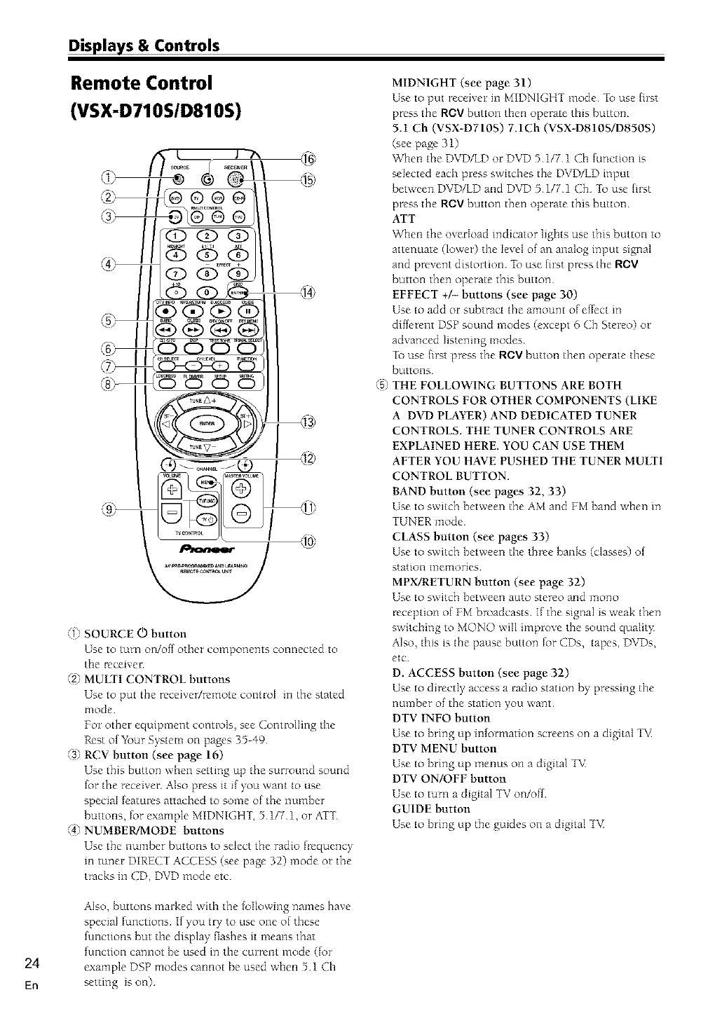
(1_ SOURCE 0 button
Use to turn on/off other components connected to
the receiver
"2) MULTI CONTROL buttons
Use to put the receiver/remote control m the stated
mode
For other equipment controls, see Controlling tile
Rest of YZ)ur System on pages 35 49
(3] RCV button (see page 16)
Use this button when setting up the surround sound
for the receiver Also press it if you want to use
special features attached to some of the number
buttons, for example MIDNIGHT, 5 117 1, or ATT
@ NUMBER/MODE buttons
Use the number buttons to select the radio frequency
in tuner DIRECT ACCESS (see page 32) mode or the
tracks m CD, DVD mode etc
/->,
MIDNIGHT (see page 31)
Use to put receiver in MIDNIGHT mode To use first
press the ROV button then operate this button
5.1 Cb (VSX-D710S) 7ACb (VSX-D810S/D850S)
(see page 31)
When the DVD/LD or DVD 5 1/7 1 Ch {unction is
selected each press switches the DVD/LD input
between DVD/LD and DVD 51/71 Ch To use hrst
press the ROV button then operate this button
ArT
When the overload indicator lights use this button to
attenuate (lower) the level of an analog input signal
and prevent distortion Zb use hrst press the R(::V
button then operate this button
EFFECT +/- buttons (see page 30)
Use to add or subtract the amount of eftect in
diftcrent DSP sound modes (except 6 Ch Stereo) or
advanced listening modes
To use hrst press the NOV button then operate these
buttons
THE FOLLOWING BUTTONS ARE BOTH
CONTROLS FOR OTHER COMPONENTS (LIKE
A DVD PLAYER) AND DEDICATED TUNER
CONTROLS, THE TUNER CONTROLS ARE
EXPLAINED HERE. YOU CAN USE THEM
AFTER YOU HAVE PUSHED THE TUNER MULTI
CONTROL BUTTON.
BAND button (see pages 32, 33)
Use to switch between the AM and FM band when in
TUNER mode
CLASS button (see pages 33)
Use to switch between the three banks (classes) of
station II] el_]o ties
MPX/RETURN button (see page 32)
Use to switch between auto stereo and mono
reception of FM broadcasts If the signal is weak then
switching to MONO will improve the sound quality:
Also, this is the pause button for CDs, tapes, DVDs,
etc
D. ACCESS button (see page 32)
Use to directIy access a radio station by pressing the
number of the station you want
DTV INFO button
Use to bring up information screens on a digital TV
DTV MENU button
Use to bring up menus on a digital T_
DTV ON/OFF button
Use to turn a digital TV on/of{
GUIDE button
Use to bring up the guides on a digital T_1
24
En
Also, buttons marked with the }allowing names have
special functions If you try to use one of these
functions but the display flashes it means that
function cannot be used in the current mode (for
example DSP modes cannot be used when 5 1 Ch
setting is on)

Displays & Controls
@ I_/DTS button (see pages 27, 29)
Use to put receiver in DOLBY DIGITAL, DOLBY
SURROUND and DTS modes
DSP button (see pages 28, 30)
Use to put receiver in one of the DSP modes
TEST TONE button (see page 21)
Use to sound the TEST TONE when setting up the
surround sound of the receiver (the 11rl/DTS mode
must be on)
SIGNAL SELECT (see page 29)
Use to select the proper signal (analog, digital) [or tile
source your are inputting On tile VSX DS10S gr
VSX D850S receivers there is all AUTO setting In
this setting the Beceiver will automatically switch
between tile analog and digital sigtlals according to
what is being input If both signals are input tile
AUTO setting will choose the digital one This setting
is convenient as the receiver will always choose the
best or appropriate signal
(E CH SELECT button (see page 21)
Use to select a speaker when setting up the surround
sound of the receiver To use hrst press the RCV
button then operate this button
CH LEVEL +/- (see page 21)
Use to set up the levels of the surround sound of the
Beceiver _b use first press the RCV button then
operate this button
FUNCTION button
Use to select the playback or recording source This
button lets you cycle through the diffcrem {unctions
of the receiver in the following order: CD, TUNER,
AUX, CDWTAPE, VCWDVR, DVD/LD, DVD 7 1 Ch,
VIDEO, and TV/SAT (VSX DglOSlD8505)
CD, TUNER, AUX, CDWTAPE, VCWDVR, DVD/LD,
VIDEO, and TV/SAT (VSX D710S)
@ LOUDNESS button
Use to switch on the loudness This feature is useful
for getting good bass and treble sounds listening at
Iow volmnes
FL DIMMER button
Use this button to make the fluorescent display (F1)
dimmer or brighter There are three brighmess
settings as well as an off setting
SETUP button (see page 35-40)
Use this button when setting up the remote control to
control other compotlents
MUTING button
Use to mute the sound or Bestore the sound if it has
been muted
,%'THE FOLLOWING BUTTONS ARE DEDICATED
TV CONTROL. THEY ARE ONLY USED FOR
CONTROLLING YOUR TV,
TV FUNC button
Use select the TV {unction
TV © button
Use to turn on/o{f the power of the T_I
TV VOLUME +/- buttons
Use to adlust the volmne on your TV
@ MENU button
Use to access diffcrem menus associated with your
DVD player
01; MASTER VOLUME +/- buttons
Use to set the ovemI1 listening volume
1Z CHANNEL +/- buttons
Use to select the stations of memorized radio
Irequencies Also use to skip tracks backward or
Iorward on CDs, DVDs, etc
@ <1 C> A V ( TUNE/ST +/-) &z ENTER buttons (see
pages 16-21)
Use these arrow buttons when setting up your
surround sound system (see pages 16 21) -fhese
buttons are also used to control DVD menus/options
and [or deck 1 of a double cassette deck player The
TUNE/ST +_ buttons can be used to find radio
[rcquencies and preset stations, respectivel),
@ DISC (ENTER) button
Use to select a disc an m multi CD player To use
first press the RCV button then operate this button
_ RECEIVER O (POWER) button
This switches between STANDBY mode and power
ON {or this receiver
_18LED DISPLAY (see pages 35-40)
This display flashes when a command is sent from
the remote control to the receiver It also flashes at
other times, {or example when teaching the receiver
preset codes, with specific meanings
25
En
Displays & Controls
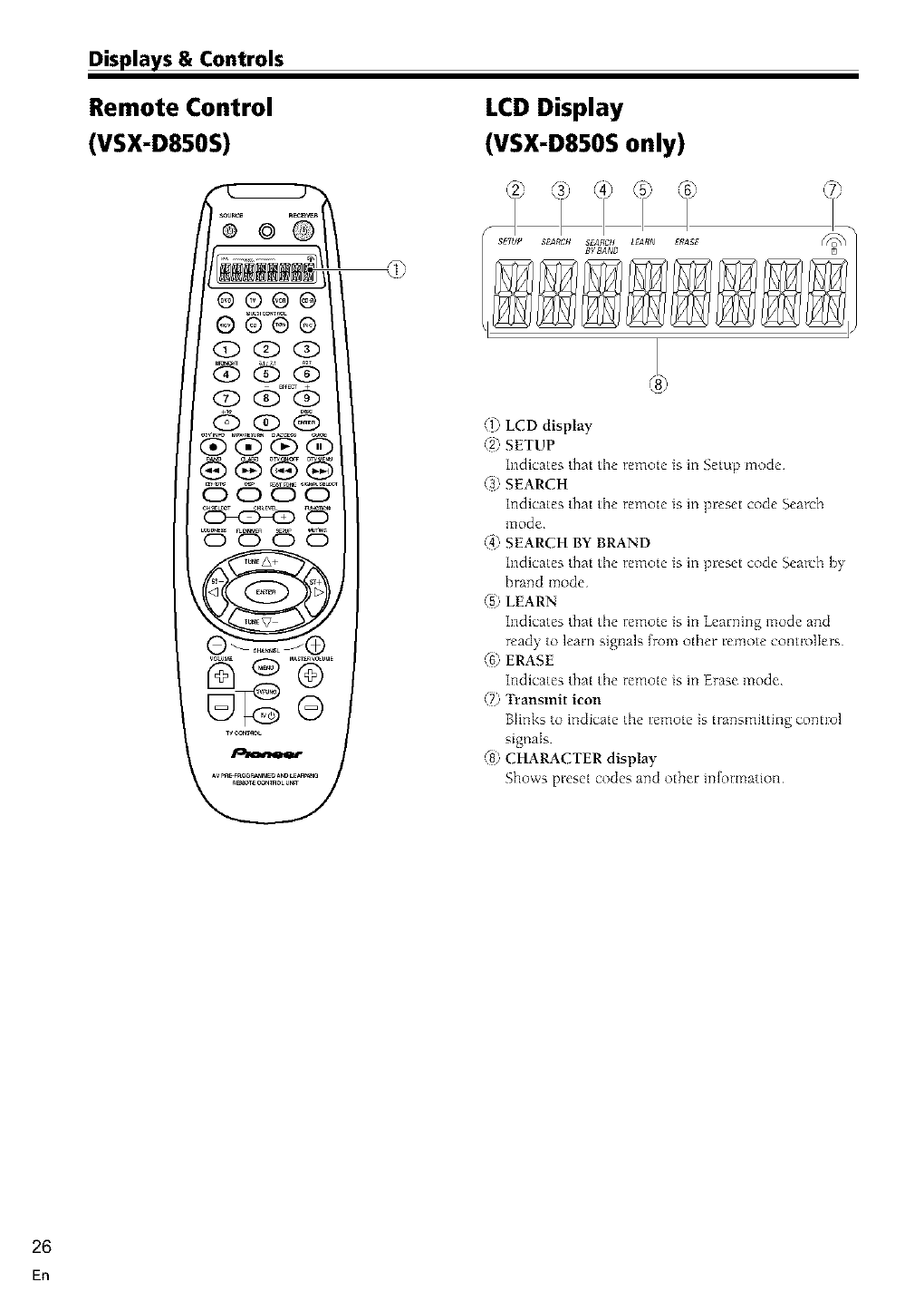
Remote Control
(VSX-D850S)
LCD Display
(VSX-D850S only)
®©
(1_ LCD display
"2) SETUP
Indicates that the remote is in Setup mode
(3_ SEARCH
indicates that the remote is in preset code Search
mode
@ SEARCH BY BRAND
Indicates that the remote is in preset code Search by
brand mode
"5) LEARN
indicates that the remote is in Learning mode and
ready to learn signals [tom other remote controllers
(f) ERASE
Indicates that the remote is in Erase mode
(Tj Transmit icon
Blinks to indicate the remote is transmitting control
signals
@ CHARACTER display
Shows preset codes and other inJormation
26
En
Learning about the Sound Modes
The sound modes are explained here
There are two cinema modes: IXI STANDARD, and ADVANCED THEATER These are designed to be used with multi
channel surround sound audio/visual sources (like DVDs and LDs) Intrinsic to home theater, these modes can deliver
realistic and powerful surround sound that recreates the movie theater experience You may need to experiment with
them to see which settings suit your home system and personal tastes
The DSP and STEREO modes are designed to be used with music sources but some DSP modes are also suited for
{din soundtracks Again, try different settings with various soundtracks to see which you like
E]D (STANDARD) mode
This mode is for pure decoding of Dolby Digital, DTS and Dolby Surround sources No special effects are added It is
good for enpying movies that have been recorded m Dolby Digital, DTS or Dolby Surround
You can identify Dolby Digital software by the P_ or I_._ marks Most Dolby Surround software is
marked I:Irl_, but unmarked software may also incorporate Dolby Surround
ADVANCED THEATER modes
MUSICAL
Simulates the acoustic environment of a large concert hall and is suitable for music or musical sources marked P_
(,,...o o ,.L) r_"
DRAMA
Simulates the relaxed environmem of a classic medimn size movie theater, and is suitable for watching dramas on
sources marked Du_ ( _ ) or mu_ou_
ACTION
Simulates the acoustic environment of a large modern movie theater You can enjo} the po\ver and dynamics of
motion picture audio which is best used with action mo_ies on sources marked ....... , _...,.,.. Lo_ Jpuuo_Nu
EXPANDED (VSX-DT10S)
This mode is especially designed to gixe sound depth to stereo sources The overall effect builds a dynamic and broad
sound space, allowing two channel (stereo) signals to faithfully' imitate a five speaker sound Use \;itb Do[by Pro
Logic for a stereo surround effect Ybu can also use with Dolby Digital sources Ior a \;ider stereo find than
STANDARD mode
5/6_D THEATER (VSX-D810S/D850S)
This mode is especially designed to give sound depth to stereo sources The overall effect builds a dynamic and
broad sound space, allo\_ing t\_o-channel (stereo) signals to faithfully imitate a six speaker sound The mode should
be used in co@unction \vitln Do[by Pro Logic for sources bearing the Ell3_ mark
27
En
Sound Modes
DSP modes
The DSP (Digital Signal Processing) modes allow you to transform your living room into a variety of different sonic
environmems when playing standard (two channel) stereo sources, Dolby Pro Logic sources, and Dolby Digital
sources DSP modes do not work when tile speakers are off
HALL 1
Simulates tile acoustic envirormlent of a large, wooden concert hall Complex delay of reflected sounds coupled with
Beverberation effects create the dynamic and beautiful sound characteristics of an orchestra performing m a concert
hall, making it suitable for classical music
HALL 2
Simulates the acoustic environmem of a concert hall with stone walls The rich reverberations and natural fullness of
the sound create the auditory impression of being in a concert hail, also making it suitable for classical music
JAZZ
Simulates the acoustic environmem of a jazz club Less delay on the reflected sounds emphasizes the sensation of
hearing a live band
DANCE
Simulates the acoustic environment and strong bass sound of a dance club A short delay on the reflected sounds
emulates the raw power of the dance music
THEATER 1
Adlusts the delay of the reflected sound to simulate the acoustic environment of a medium sized movie theater
THEATER 2
Simulates the acoustic environmem of a theater while maintaining proper localization of each channel
5/6Ch STEREO (VSX D810S/D850S)
This mode reproduces stereo sound but uses all the speakers m the system to reduce a rich, all-around sound
MEMO:
•When using 95 kHz PCM pla),back, STANDARD, ADVANCED THEATER, and DSP sound modes are not
available
28
En
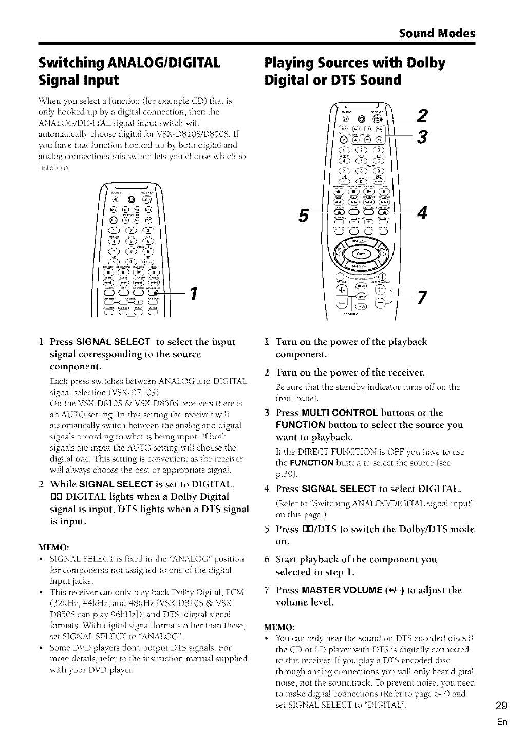
Sound Modes
Switching ANALOG/DIGITAL
Signal Input
When you select a function (for example CD) that is
only hooked up by a digital comlection, then tile
ANALOG/DIGITAL signal input switch will
automatically choose digital for VSX-D810S/D8505 If
you have that function hooked up by both digJtaI and
analog connections this switch lets you choose which to
listen to
@®@@
O@G®
@@@@
Playing Sources with Dolby
Digital or DTS Sound
2
3
1 Press SIGNAL SELECT to select the input 1
signal corresponding to the source
component. 2
Each press switches between ANALOG and DIGITAL
signal selection (VSX-D710S)
On the VSX D810S gr VSX D850S receiver-; there is
an AUTO setting In this setting the receiver will 3
automatically switch between the analog and digital
signals according to what is being input I[ both
signals are input the AUTO setting will choose the
digital one This setting is convenient as the receiver
will always choose the best m appropriate signal
2 While SIGNAL SELECT is set to DIGITAL, 4
Drl DIGITAL lights when a Dolby Digital
signal is input, DTS lights when a DTS signal
is input.
MEMO:
•SIGNAL SELECT is fixed in the "ANALOG" position
for components not assigned to one of the digital
input jacks
• This receiver can only play back Dolby Digital, PCM
(32kHz, 44kHz, and 48kHz [VSX D810S £r VSX
D8505 can play' 96kHz]), and DTS, digital signal
formats With digital signal (ormats other than these,
set SIGNAL SELECT to 'ANALOG"
• Some DVD players dont output DTS signals For
more details, refer to the instruction manual supplied
with your DVD player
5
6
7
Turn on the power of the playback
component.
Turn on the power of the receiver.
Be sure that the standby indicator turns off on the
(font panel
Press MULTI CONTROL buttons or the
FUNCTION button to select the source you
want to playback.
If the DIRECT FUNCTION is OFF you have to use
the FUNCTION button to select the source (see
p39)
Press SIGNAL SELECT to select DIGITAL.
(Rcfrr to 'Switching ANALOG/DIGITAL signal input"
on this page)
Press rlrl/DTS to switch the Dolby/DTS mode
Oil.
Start playback of the component you
selected in step 1.
Press MASTER VOLUME (+/-) to adjust the
volume level.
MEMO:
•You can only hear the sound on DTS encoded discs if
the CD m LD player with DTS is digitally connected
to this receiver I[ you play a DTS encoded disc
through analog connections you will only hear digital
noise, not the soundtrack To prevent noise, you need
to make digital connections (Re{er to page 6 7) and
set SIGNAL SELECT to 'DIGITAL" 29
En
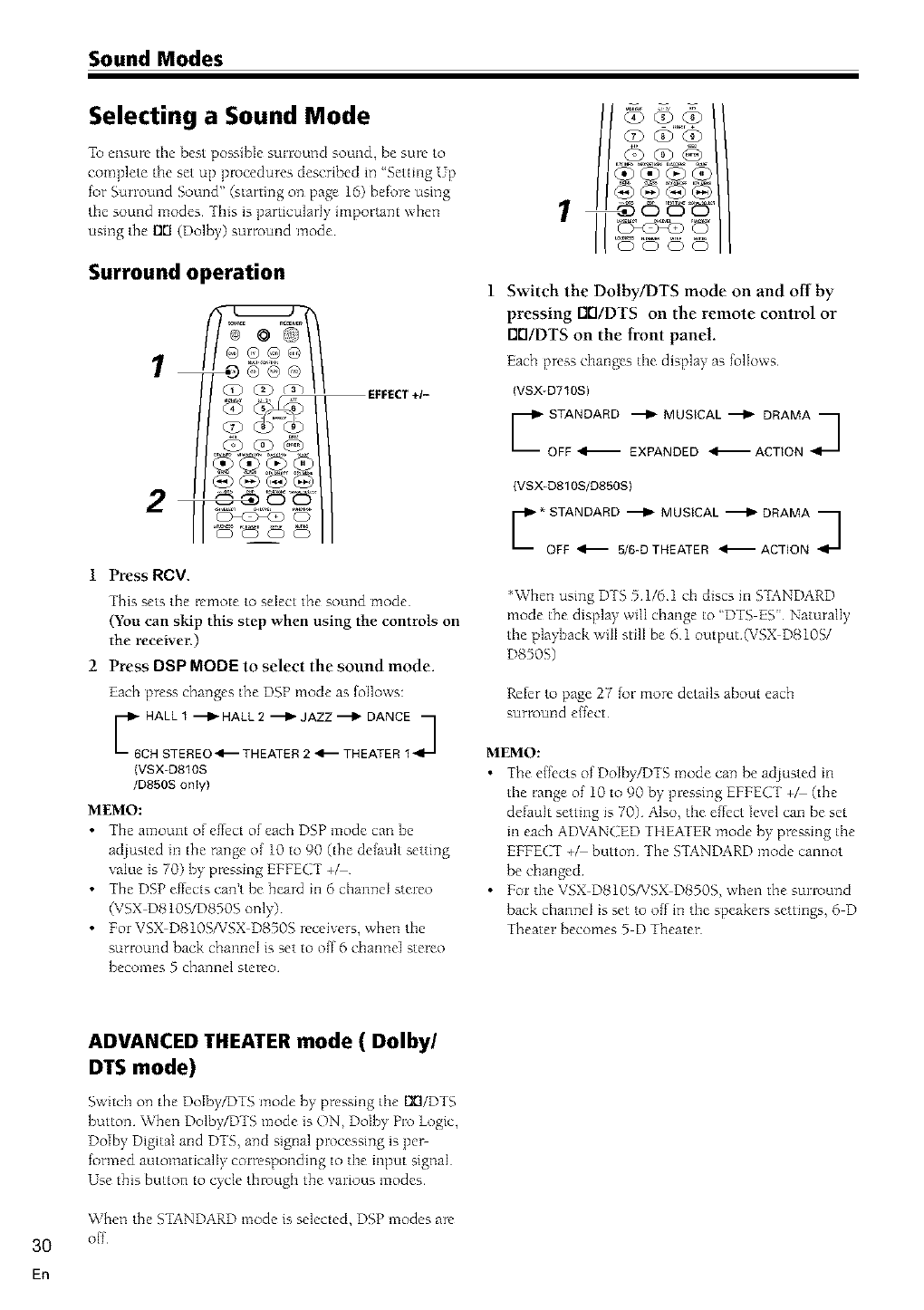
Sound Modes
Selecting a Sound Mode
To ensure tile best possible surround sound, be sure to
complete the set up procedures described in "Setting Up
for Surround Sound" (starting on page 16) before using
tile sound modes This is particularly important when
using the rlrl (Doll)y) surround mode
Surround operation
1
EFFECT+1-
2,,
1 Press RCV.
This sets the remote to select the sound mode
(You can skip this step when using the COlUrols on
the receiver.)
2 Press DSP MODE to select the sound mode.
Each press changes the DSP mode as lollows:
57r2L2ZZZ?
(VSX-D810S
/D850S oniy)
MEMO:
•7he amount of effect of ead_ DSP mode can be
adlusted in the range of 10 to 90 (the default setting
value is 70) by pressing EFFECT +_
•The DSP effects can't be heard in 6 channel stereo
(VSX DS10S/D850g only)
• ForVSX DS10SfVSX D8505 receivers, when the
surround back chamleI is set to off 6 channel stereo
becomes 5 channel stereo
Q) G) G)
Q) <O (X)
0000
Switch the Dolby/DTS mode on and off by
pressing EI0/DTS on the remote control or
Elt'I/DTS on the front panel.
Each press changes the display as follows
(VSX-D710S} Lr ri%TS
(VSX-D810S/D850S)
*When using DTS 5 1/6 1 ch discs in STANDARD
mode the display' wilI change to "DTS ES" Naturally
the playback will still be 61 output (VSX D810S/
D8505)
Refer to page 27 for more details about each
surround effect
MEMO:
• The effects of Dolby/DTS mode can be adlusted in
the range of 10 to 90 by pressing EFFECT +_ (the
default setting is 70) Also, the effect level can be set
in each ADVANCED THEATER mode by pressing the
EFFECT +_ button The STANDARD mode cannot
be changed
• For the VSX DS10SfVSX D8505, when the surround
back channel is set to off in the speakers settings, 6 D
Theater becomes 5 D Theater
3O
En
ADVANCED THEATER mode ( Dolby/
DTS mode)
Switch at1 the DoIby_)TS mode by pressing the [X]/DTS
button When Dolby/DTS mode is ON, Dolby Pro |ogle,
Dolby Digital and DTS, and signal processing is per-
formed automatically corresponding to the input signal
Use this button to cycle through the various modes
When the STANDARD mode is selected, DSP modes are
off
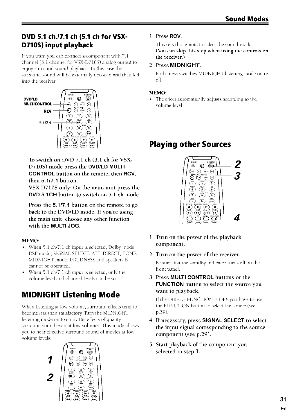
Sound Modes
DVD S.1 ch.17.1 ch (5.1 ch for VSX-
D710S) input playback
Ifyou want you can connect a component with 7l
channel (5 1channel _r VSX D710S) analog outputto
el_oy surround sound playback¸In thiscasethe
surround sound willbe externallydecoded and then fed
intothe receive];¸
DVDILD
MULTICONTROL_ _@ @
To switch on DVD 7.1 ch (5.1 ch for VSX-
D710S) mode press the DVD/LD MULTI
OONTROL button on the remote, then ROV,
then 5.117A button.
VSX-D710S only: On the main unit press the
DVD 5.1 C Hbutton to switch on 51 ch mode
Press the 5.1/7.1 button on the remote to go
back to the DVD/LD mode. If you're using
the main unit, choose any other function
with the MULTI dOG.
MEMO:
•When 5 1 oh/7 1 ch input is selected, Dolby mode,
DSP mode, SIGNAL SELECT, ATT, DIRECT, TONE,
MIDNIGHT mode, LOUDNESS and speakers B
cannot be operated
•When 5 1 oh/7 1 ch input is sebcted, only the
volume level and channel levels can be set
MIDNIGHT Listening Mode
When listening at low volume, surround eIfccts tend to
become less than satisfacto% Turnthe MIDNIGHT
listening mode on to enloy the ef[ects of quality
surround sound even at low volumes 7his mode allows
you to hear ef[cctive surround sound of movies at low
volume levels
1
1 Press RCV.
This sets the remote to select the sound mode
(You can skip this step when using the controls on
the receiver.)
2 Press MIDNIGHT.
Each press switches MIDNIGHT listening mode on or
off
MEMO:
•The effect automaticalI> adjusts according to the
volume levN
Playing other Sources
2
3
@@@@
OOO_ 4
1
2
Turn on the power of the playback
component.
Turn on the power of the receiver.
Be sure that the standby indicator turns o(fon the
(rout panel
3 Press MULTI OONTROL buttons or the
FUNOTION button to select the source you
want to playback.
1[ the DIRECT FUNCTION is OFF you have to use
the FUNCTION button to select the source (see
p39)
4 If necessary, press SIGNAL SELECT to select
the input signal corresponding to the source
component (see p29).
5 Start playback of the component you
selected in step 1.
31
En
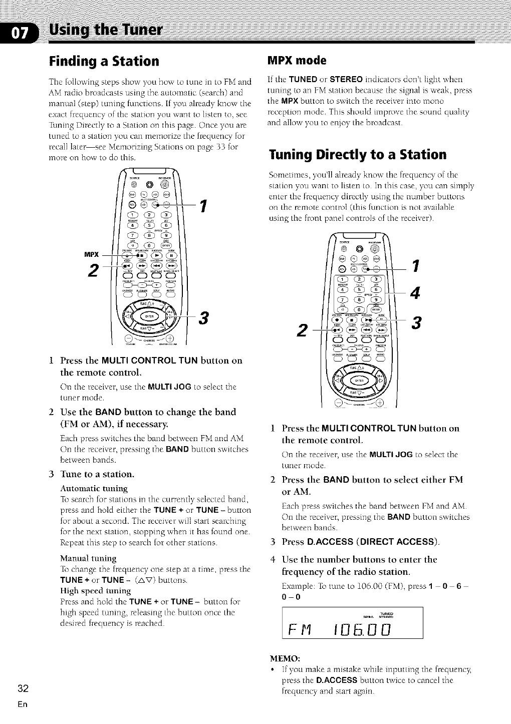
Finding a Station
The following steps show you how to tulle ill to PM and
AM radio broadcasts using the automatic (search) and
manual (step) tuning [unctions If you already know tile
exact fl:equency of tlne station you want to listen to, see
_ianing Directly to a Station on this page Once you are
tuned to a station you can memorize tile flequency for
recall later see Memonzing Stations on page 33 {or
more on how to do this
MPX mode
It tile TUNED or STEREO indicators don't light when
tuning to an FM station because the signal is weak, pl_ss
the MPX button to switch the receive]; into mono
reception mode¸ This should impl_ve the sound quality
and allow you to el_oy the broadcast¸
Tuning Directly to a Station
Sometimes, you'lI already know tile frequency of tile
station you want to listen to In this case, you can simply
enter tile frequency directly using the number buttons
on tile remote control (this function is not avaihNe
_t / using tile front [?and controls of tile receiver)
MPX __
2 1
4
Press the MULTI CONTROL TUN button on
the remote control.
On the receher, use the MULTI JOG to select the
tuner mode @_.o_
Use the BAND button to change the band
(FM or AM), if necessary.
Each press switches the band between FM and AM
On tile receiver, pressing the BAND button switches
between bands
3 Tune to a station.
Automatic tuning
_b search for stations in tile currently selected band,
press and hold either the TUNE + or TUNE -button
for about a second Tile receiver will start searching
for the next station, stopping when it has found one
Repeat this step to search tot other stations
1 Press the MULTI CONTROL TUN button on
the remote control.
()n the receiver, use the MULTI JOG to select the
tuner l_lode
2 Press the BAND button to select either FM
or AM.
Each press switches the band between FM and AM
On tile receiver, pressing the BAND button switches
between bands
3 Press D.ADDESS (BIRECTADDES8).
Manual tuning
_b change the frequency one step at a time, press tile
TUNE + or TUNE- (AV) buttons
High speed tuning
Press and hold the TUNE + or TUNE- button for
high speed tuning, releasmg the button once tile
desired frequency is reached
4Use the number buttons to enter the
frequency of the radio station.
Example: _b tune to 10600 (FM), press 106
0 0
m_m
Fl'q 106.00
32
En
MEMO:
•If you make a mistake while inputting tile fl;equency;
press the B.ABOESS button twice to cancel the
frequency and start again
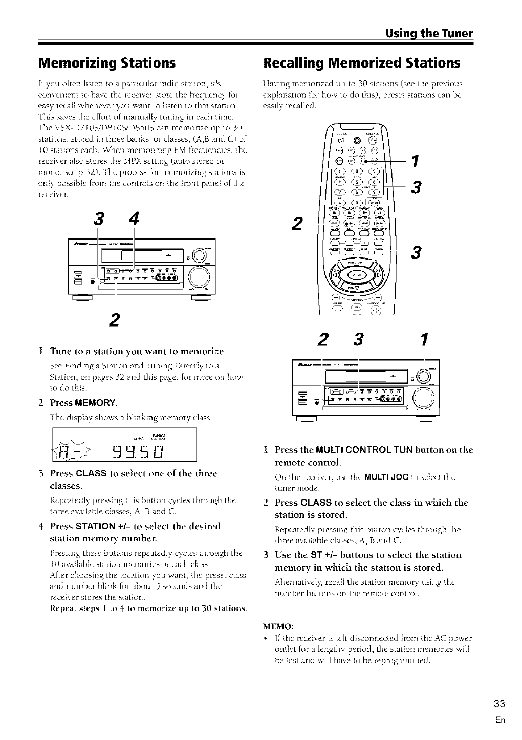
Using the Tuner
Memorizing Stations Recalling Memorized Stations
If you ohen listen to a particular radio station, it's
convenient to have the receiver store the (requency _r
easy recall whenever you want to listen to that station¸
This saves the e_rt of manualIy tuning ill each time¸
The VSX D7105/DSlOS/D850.S can memorize up to 30
stations, stored in three banks, or cIasses, (A,B and C) of
10 stations each¸ When memorizing FM fi:equencies, the
receiver also stol_s the MPX setting (auto stereo or
mono, see p32) The process _r memorizing stations is
onIy possible from the controls on the fl_nt panel o[ the
receivel:
Hazing memorized up to 30 stations (see the previous
explanation [or how to do this), preset stations can be
easily ¸ recalled¸
3 4 2 '
,_ _ _ _-_-_
2
1 Tune to a station you want to memorize.
.See Finding a Station and _aning Directly to a
.Station, on pages 32 and this page, (or more on how
to do this
2 Press MEMORY
The displa)+ shows a blinking memor)+ class
g_ 3.S U
3 Press CLASS to select one of the three
classes.
Repeatedly pressing this button cycles tbrougb the
three available classes, A, B and C
4 Press STATION +/- to select the desired
station memory number.
Pressing these buttons repeatedly cycles through the
10 available station memories in each class
After choosing the location you want, the preset class
and number blink for about 5 seconds and the
receiver stores the station
Repeat steps t to 4 to memorize up to 30 stations.
1
3
(10 (13 (13 (13
CD CD CD CD
3
_+
2 3 1
/
1 Press the MULTI CONTROL TUN button on the
remote control
On the receiver, use the MULTI JOG to select the
tuner mode
2 Press CLASS to select the class in which the
station is stored
Repeatedly pressing this button cycles through the
three available classes, A, B and C
3 Use the ST +/- buttons to select the station
memory in which the station is stored
Ahernativel)+, recall the station memory using the
number buttons on the remote control
MEMO:
•If the receiver is lea disconnected flom the AC power
outIet for a lengthy period, the station memories wilI
be lost and will have to be mprogrammed
33
En
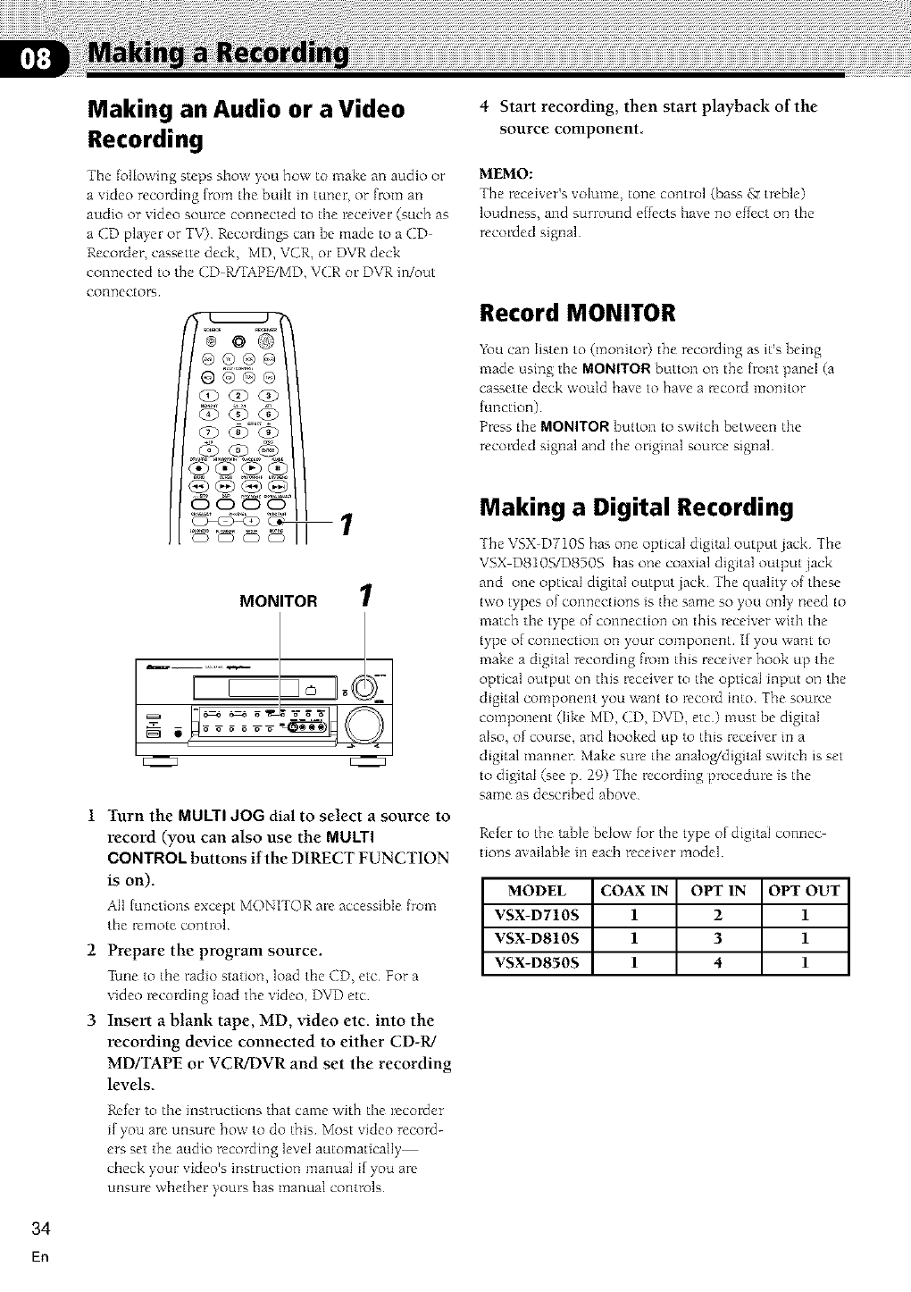
Making an Audio or a Video
Recording
The following steps show you how to make an audio or
a video recording {tom the built in tuner, or from an
audio or video source connected to tile receiver (such as
a CD player or TV) Recordings can be made to a CD
Recorder, cassette deck, MD, VCR, o1:DVR deck
connected to the CD WTAPK/MD, VCR or DVR in/out
connectors
4 Start recording, then start playback of the
source component
MEMO:
The receiver's volume, tone control (bass gr treble)
loudness, and surround elfccts have no effect on tile
recorded signal
Record MONITOR
MONITOR 1
1 Turn the MULTI JOG dial to select a source to
record (you can also use the MULTI
CONTROL buttons if the DIRECT FUNCTION
is on).
All {unctions except MONITOR are accessible {rom
the remote control
2 Prepare the program source.
Piane to the radio station, load the CD, etc For a
video recording load the video, DVD etc
3 Insert a blank tape, MD, video etc. into the
recording device connected to either CD-R/
MD/TAPE or VCR/DVR and set the recording
levels
Refer to the instructions that came with the recorder
if you are unsure how to do this Most video record-
ers set the audio recording level automatically
check your video's instruction manual if you are
unsure whether yours has manual controls
You can listen to (monitor) the recording as it's being
made using the MONITOR button on the front panel (a
cassette deck would have to have a record monitor
[unction)
Press the MONITOR button to switch between the
recorded signal and the original source signal
Making a Digital Recording
The VSX DT10S has one optical digital output jack The
VSX D810S/D850S has one coaxial digital output jack
and one optical digital output jack The quality of these
two types of connections is the same so you only need to
match the type of connection on this receiver with the
type of connection on your component if you want to
make a digital recording from this receiver hook up the
optical output on this receiver to the optical input on the
digital component you want to record into The somve
component (like MD, CD, DVD, etc) must be digital
also, of course, and hooked up to this receiver in a
digital manner Make sure the analo_digitaI switch is set
to digital (see p 29) -fhe recording procedure is the
same as described above
Refer to the table below for the type of digital connec
tions available in each receiver model
MODEL COAX IN OPT IN OPT OUT
VSX-D710S 1 2 1
VSX-D810S l 3 l
VSX-D850S 141
34
En
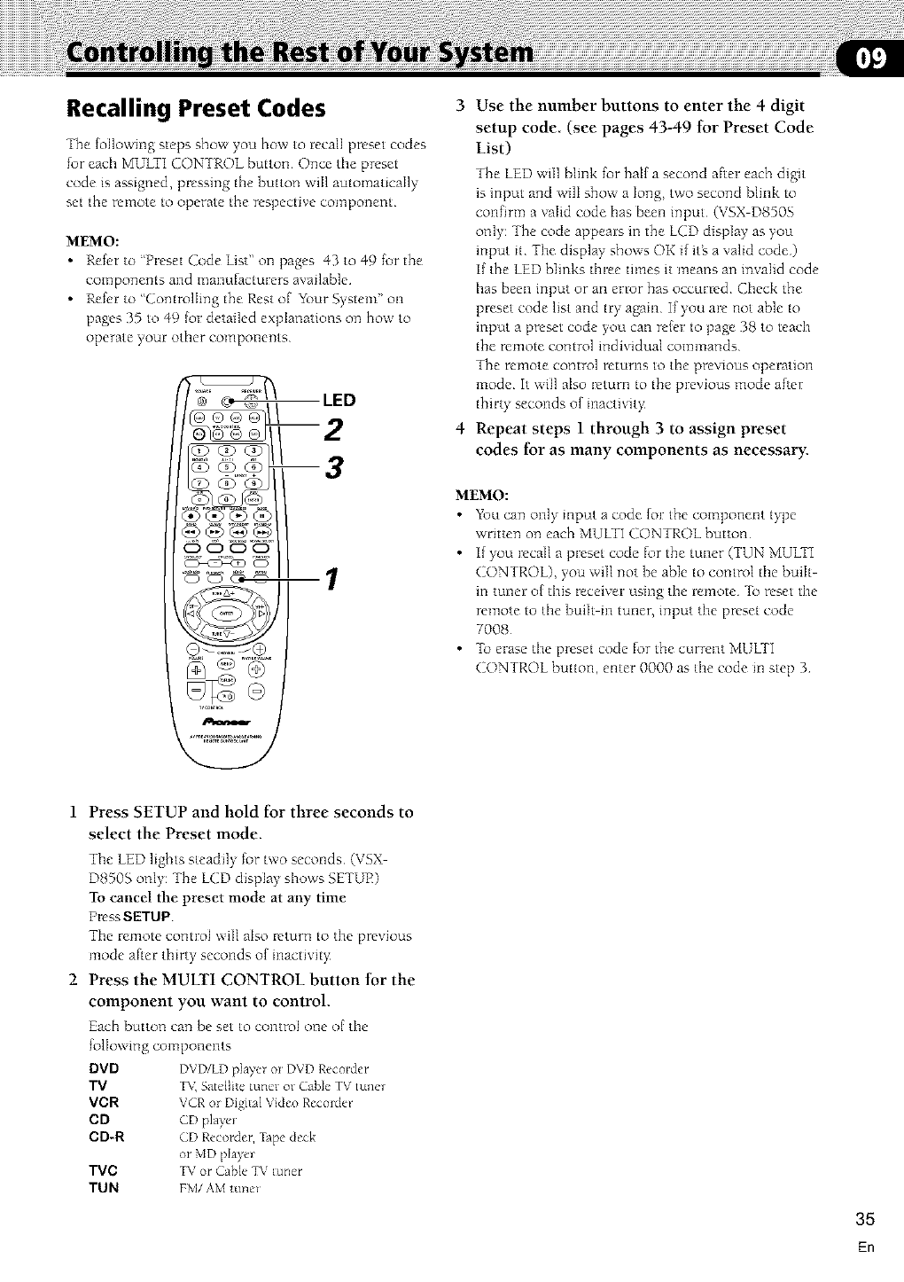
Recalling Preset Codes
The k}Ilowing steps show you how to recall preset codes
for each MULTI CONTROL button Once tile preset
code is assigned, pressing the button will automatically
set the remote to operate the respective component
MEMO:
•Refer to 'Preset ([ode List" on pages 43 to 49 for the
components and manufacturers available
• Refer to "Controlling the Rest of Ybur System" on
pages 35 to 49 k)r detailed explanations on bow to
operate your other components
LED
m2
m3
@Q:9@ @
CD CD CD C3
co !
0 .... ®
Use the number buttons to enter the 4 digit
setup code (see pages 43-49 for Preset Code
List)
The LED will blink for half a second after each digit
is input and will show a long, two second blink to
confirm a valid code has been input (VSX D8505
only: The code appears in the LCD display as you
input it The display' shows OK if itg a valid code)
I[ the LED blinks three times it means an invalid code
has been input or an error has occurred Check the
preset code list and try again If you are not able to
input a preset code you can refer to page 38 to teach
the remote control individual commands
The remote control returns to the previous operation
mode It will also return to the previous mode after
thirty seconds of inactivity
Repeat steps 1 through 3 to assign preset
codes for as many components as necessary.
MEMO:
•You can onl_ input a code {or the component bpe
written on each MUIXI CONTROL button
• I[ you recaI1a preset code for the tuner (TUN MULXI
CONTROL), you will not be able to control the built-
in tuner of this receiver using the remote To reset the
remote to the built in tuner, input the preset code
7008
•To erasethe preset code for the current MULTI
CONTROL button, enter 0000 as the code m step 3
1 Press SETUP and hold for three seconds to
select the Preset mode.
The LED ligbts steadily for two seconds (VSX
D8505 only: The LCD display shows SETUE)
To cancel the preset mode at any time
PmssSETUP
The remote control will also return to the previous
mode after thirty seconds of inactivity:
2 Press the MULTI CONTROL button for the
component you want to control
Each button can be set to control one of the
following components
DVD DVD/LD pJ%er o_ DVD Recolder
TV T_( Satdlite tuner or Cable TV tunel
VCR VCR o_ Digital Video Recoide_
CD CD playe_
CD-R CD Recorder, Tape deck
or MD pl%e_
TVC TV or Cable TV tuner
TUN FM/AM tune_
35
En
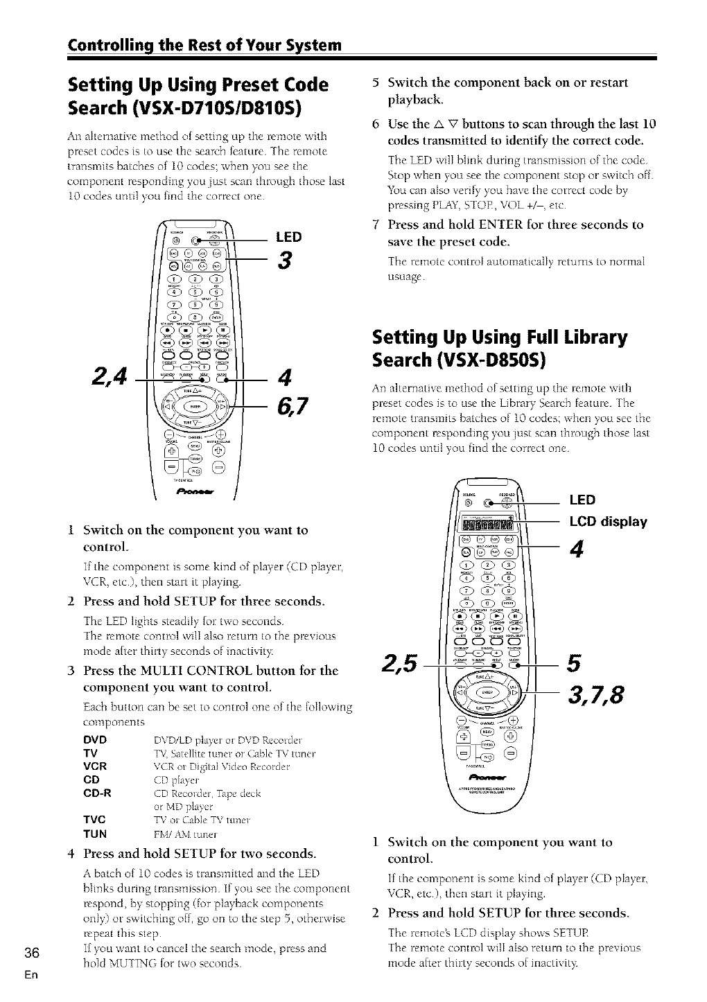
Controlling the Rest of Your System
36
En
Setting Up Using Preset Code
Search (VSX-D710S/D810S)
All alternative method of setting up the remote with
preset codes is to use tile search feature The remote
transmits batches of 10 codes; when you see tile
component responding you just scan through those last
10 codes until you find tile correct one
2,4
LED
0000
Q .... Q
Switch on the component you want to
control.
If tile component is some kind of playeF (CD player,
_vCR, etc), then _tart it pJaying
Press and hold SETUP for three seconds.
The LED lights steadily {or two seconds
The remote control will also retunn to the previous
mode a{ter thirty seconds of inactivit}
Press the MULTI CONTROL button tor the
component you want to control.
Each button can be set to control one of the {ollowmg
CO123poilen [s
DVD DVD/LD player or DVD Recordm
TV TV Satellite' tuner oz Cable TV mne_
VCR VCR or Digital Video Recorder
CD CD pla}e_
CD-R CD Recorder, TJpe deck
o/MD player
TVC TV ol Cable TV tunel
TUN FM/AM tune_
4 Press and hold SETUP tor two seconds.
A batch of 10 codes is transmitted and the LED
blinks during transmission If you see the component
respond, by stopping (for playback componems
only) or switching off, go on to tlnestep 5, otherwise
repeat this step
If you want to cancel tlne search mode, press and
hold MUTING {or two seconds
5 Switch the component back on or restart
playback.
6 Use the A V buttons to scan through the last 10
codes transmitted to identity the correct code.
Ihe LED will blink during transmission of the code
Stop when you see the component stop or switch of[
Ybu can also verif) you have the correct code by
pressing PLAY,STOR, VOL +_, etc
7 Press and hold ENTER for three seconds to
save the preset code.
The remote control automatically returns to normal
USLlage
Setting Up Using Full Library
Search (VSX-D850S)
An alternative method of setting up the remote with
preset codes is to use the Library Search feature The
remote transmits batches of 10 codes; when you see the
component responding you just scan through those last
10 codes until you lind the correct one
LED
-- LCD display
--4
_0
1 Switch on the component you want to
control.
If the component is some kind of playeF (CD pJayer,
VCR, etc), then start it playing
2 Press and hold SETUP for three seconds
The remoteg LCD display shows SETUR
The remote control will also return to the previous
mode after thirty seconds of inactivity:
Controlling the Rest of Your System
3Use the <I > buttons to select the Full
Library Search mode.
The remote _,LCD disphy shows SEARCH
4 Press the MULTI CONTROL button for the
component you want to control
Each button can be set to control one of the following
COII]poI]ents
DVD DVD/LD pJa}er o_ DVD Recotde_
TV T_ Satellite tuner or CaNe TV tune_
VOR VCR m Digital Video Recordel
CD CD playe_
CD-R CD Recorder, >ape deck
or MD pla) el
TVC TV or Cable TV toner
TUN FM/AM tune_
5 Press and hold SETUP for two seconds.
A batch of 10 codes is transmitted and the LED
blinks during transmission
If you see the component respond, by stopping (for
playback componems only) or switching off, go on to
the step 6, otherwise repeat this step After the ten
codes have been sent the search icon blinks
If you want to cancel the seawb mode, press and
hold MUTING for two seconds
6 Switch the component back on or restart
playback.
7 Use the A V buttons to scan through the last
10 codes transmitted to identify the correct
code
The transmission icon is on while the codes are sent
out Stop when you see the component stop or
switch off -fbe LCD display' shows the ID
Ybu can also verify you have the correct code by
pressing PLAY,STOE, VOL +_, etc
8 Press and hold ENTER for three seconds to
save the preset code.
2 Press and hold SETUP tor three seconds.
Setting Up Using Brand Name
Search (VSX-D850S only)
An alternative method of setting up the remote with
preset codes is to use the Brand Search feature The
remote transmits batches of 10 codes; when you see the
component responding you just scan through those last
10 codes until you fred the correct one
1 Switch on the component you want to control.
If the component is some kind of player (CD player,
VCR, etc), then start it playing
The remote _,LCD display shows SETUE
The remote control wilI also return to the previous
mode after thirty seconds of inactivi D
Use the <_ t> buttons to select the Brand
Search mode, then press ENTER
The remote _,LCD display shows BRAND SEARCH
Press the MULTI CONTROL button for the
component you want to control.
Each button can be set to control one of the following
COlllponents
DVD DVD/LD player m DVD Recmde_
TV TV,Satellite tuner or Cable TV tuner
VCR VCR or Digital Video Reco_de_
CD CD pla}e_
CD-R CD Recmde_, TJpe deck
o/MD player
TVC TV or Cable TV tune/
TUN FM/AM tuner
Use the A V buttons to select the brand of
the component.
Tbe brand names appear in the remote_ LCD display:
I[ the brand of your component doesn't appear then
you can't use this feature
6 Press and hold SETUP tor two seconds.
7
8
A batch ofi0codes is transmitted and the transmission
icon is on while the codes are sent out After all ten
codes have been sent the seawh icon blinks
If you see the corn ponent respond, by stopping (for
phyback components only) or switching off, go on to
the step 6, otherwise repeat this step
If you want to caned the search mode, press and bold
MUTING lor two seconds
Switch the component back on or restart
playback.
Use the A V buttons to scan through the last 10
codes transmitted to identity the correct code.
The transmission icon is on while the codes are sent
out Stop when you see the component stop or
switch off The display shows the ID
You can also verify' you have the correct code by
pressing PLAY,STOE, VOL +&, etc
Press and hold ENTER for three seconds to
save the preset code
37
En
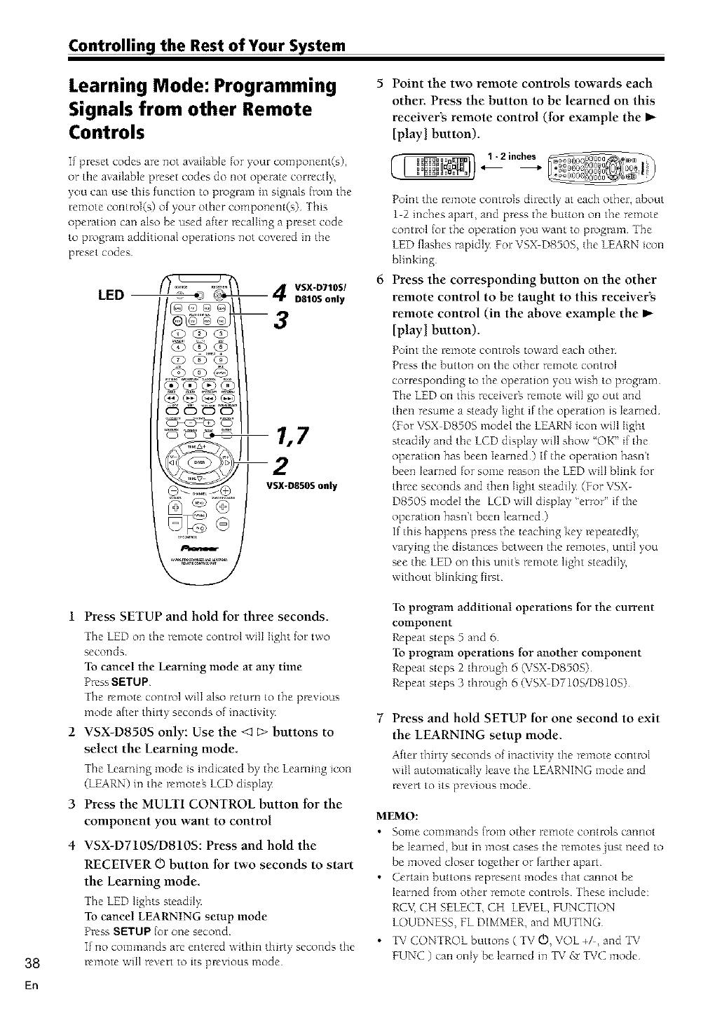
Controlling the Rest of Your System
Learning Mode: Programming
Signals from other Remote
Controls
If preset codes are not available for your component(s),
or tile available preset codes do not operate correctly,
you call use this functio_ to program ill signals {tom the
remote control(s) of your other componem(s) This
operation can also be used after recalling a preset code
to program additional operations not covered in the
preset codes
(2) <xS"<b
OO (?O(E) (iO
o .. ,............
CD CD CDCD
_o
--4 VSX-D710S/
D810S only
--3
1,7
--2
VSX-D850S only
Point the two remote controls towards each
other. Press the button to be learned on this
receiver's remote control (tor example the
[play I button).
Point tile remote controls directly at each other, about
1 2 inches apart, and press the button on the remote
control [or the operation you want to program The
LED flashes rapidl), For VSX D8505, tile LEARN icon
blinking
Press the corresponding button on the other
remote control to be taught to this receiver's
remote control (in the above example the _-
[playl button).
Point tile remote controls toward each other
Press tile button on tile other remote control
corresponding to the operation yrou WiShtOprogram
The LED on this receiverg remote will go out and
then resume a steady light if the operation is learned
(For VSX D850S model tile LEARN icon will light
steadily and tile LCD display' will show 'OK" if the
operation has been learned) If the operation hasn't
been learned for some reason the LED wilI blink lot
three seconds and then light steadiI> (For VSX-
D850S model the LCD will display 'error" if the
operation hasn't been learned)
If this happens press the teaching key mpeatedI 5
varying the distances between tile remotes, until you
see tile LED on this unitg remote light steadiI 5
without blinking flr-;t
38
1 Press SETUP and hold for three seconds.
The LED o_ the remote control will light tot two
secoIlds
To cancel the Learning mode at any time
Press SETUP
The remote ccmtrol will also return to the previous
mode alter thirt), seco_lds of inactivit),
2 VSX-D850S only: Use the < E> buttons to
select the Learning mode.
The |earning mode is indicated by the Learning icon
(LEARN) in tile remoteg LCD display:
3 Press the MULTI CONTROL button tor the
component you want to control
4 VSX-D710S/DS10S: Press and hold the
RECEIVER O button tor two seconds to start
the Learning mode
The LED lights steadily
To cancel LEARNING setup mode
Press SETUP {or one second
If no commands are entered within thirty seconds tile
remote will revert to its previous mode
To program additional operations [or the current
component
Repeat steps '5a_ld 6
To program operations tot another component
Repeat steps 2 through 6 (VSX D850S)
Repeat steps 3 through 6 (VSX D710S/D810S)
Press and hold SETUP for one second to exit
the LEARNING setup mode.
After thirty secotlds of inactivity tile remote control
will automatically leave the LEARNING mode and
revert to its previous mode
MEMO:
• Solne colnlnands _roln other re_]ote controls cailnot
be learned, but m most cases the remotes just need to
be moved closer together or farther apart
• Certain buttons represent modes that cannot be
learned from other remote controls These include:
RCV, CH SELECT, CH LEVEL, FUNCTION
LOUDNESS, FL DIMMER, and MUTING
• TV CONTROL buttons ( TV O, VOL +F, and TV
FUNC ) call only be learned in TV &rTVC mode
El1
Controlling the Rest of Your System
Erasing One of the Remote
Control Button Settings
This erases one of the buttons you have programmed
and restores tile factory installed preset to that button
VSX D71OSIDSIOS:
1 Press SETUP and hold for three seconds
Tile LED on tile remote control will light for two
secotlds
2 Press the MULTI CONTROL button relating
to the function of the button to be cleared
The remote control will return to the previous mode
after thirty seconds of mactivit),
3 Press the RECEIVER © button twice within
three seconds to start erase mode
The LED blinks
4 Press the button to be cleared for three
seconds.
The LED ligllts steadil), for three secotlds atld then
goes off
5 Repeat steps 4 to erase other codes.
6 Press and hold the SETUP button for one
second to exit the erase mode.
vsx D8505:
1 Press SETUP and hold for three seconds
The LED on the remote control will light for two
seconds and the display' shows SETUP
2 Use the < t> buttons to select the Erase mode.
The LCD display' shows ERASE
3 Press the MULTI CONTROL button relating
to the function of the button to be cleared.
4 Press the button you want to clear.
5 Repeat steps 3-4 to erase other codes.
Clearing All the Remote
Control Settings
Clears all presets, all learned functions and restores the
factory presets
1 Press SETUP and hold for three seconds.
For the VSX DT10S and VSX D810S the LED on the
remote control lights for two seconds For the VSX
D8505 the SETUP icon lights
If you want to cancel the Clearing mode, press
SETUP
The remote control will also return to the pre ious
mode after thirty seconds of inactivit_
2 Use the number buttons to enter 0123
The LED light {or half a second for each digit input
On the VSX-D7105 and VSX D8105 the LED lights
{or two seconds to indicate that the setings have been
restored to the Jactory presets (If the LED blinks
three times, then you made a mistake with the
code--try re-entering it) On the VSX D850S the
LCD displays 0123 and then "OK" Jor two seconds if
the [our digit code has been accepted if any error has
occurred display' will blink three times
Direct Function
The direct lunction is a useful leature which allows you
keep the receiver in one function (for example, CD)
while putting the remote control in a different function
This could let you, [or example, use the remote control
to set up and listen to a CD on the receiver and then use
the remote control to rewind a tape in your VCR while
you continue to listen to your CD player
When the DIRECT function is ON any MULTI
CONTROL button you press will change the function of
both the receiver and the remote control When you
turn the DIRECT function OFE you can operate the
remote control without aJJecting the receiver Thus you
could switch the remote control the VCR and operate
that component while the mceiver plays a diftcrent
compotlent
To set a MULTI CONTROL button to DIRECT ON or
DIRECT OFF:
1 Press SETUP and hold tor three seconds.
On the VSX D7105 and VSX D810S the LED on the
remote control will light for two seconds Ot_ the
VSX-D850S the LCD display SETUP icon will light
I[ you want to cancel the Direct Function mode, press
SETUP
The remote co_ltrol will also return to the pre ious
mode after thirty secondsof inactivit_
2 Press the MULTI CONTROL button that you
want to set up.
Use the number buttons to enter 9990
(DIRECT ON) or 9995 (DIRECT OFF)
The LED will ligllt for half a second on each digit
input Then, on the VSX-D710S and VSX DS10S the
LED will light {or two seconds to indicate that itg
been correctly set (If the LED blinks three times,
then you made a mistake with the code try m
entering it) On the VSX-D850S, the LCD will display
'OK" to show the lout digit code has been accepted
if it hasn't been accepted the display will blink three
[ii_les
MEMO:
•TV CONT doesnt have this feature and thus can't use
the DIRECT FUNCTION
39
En
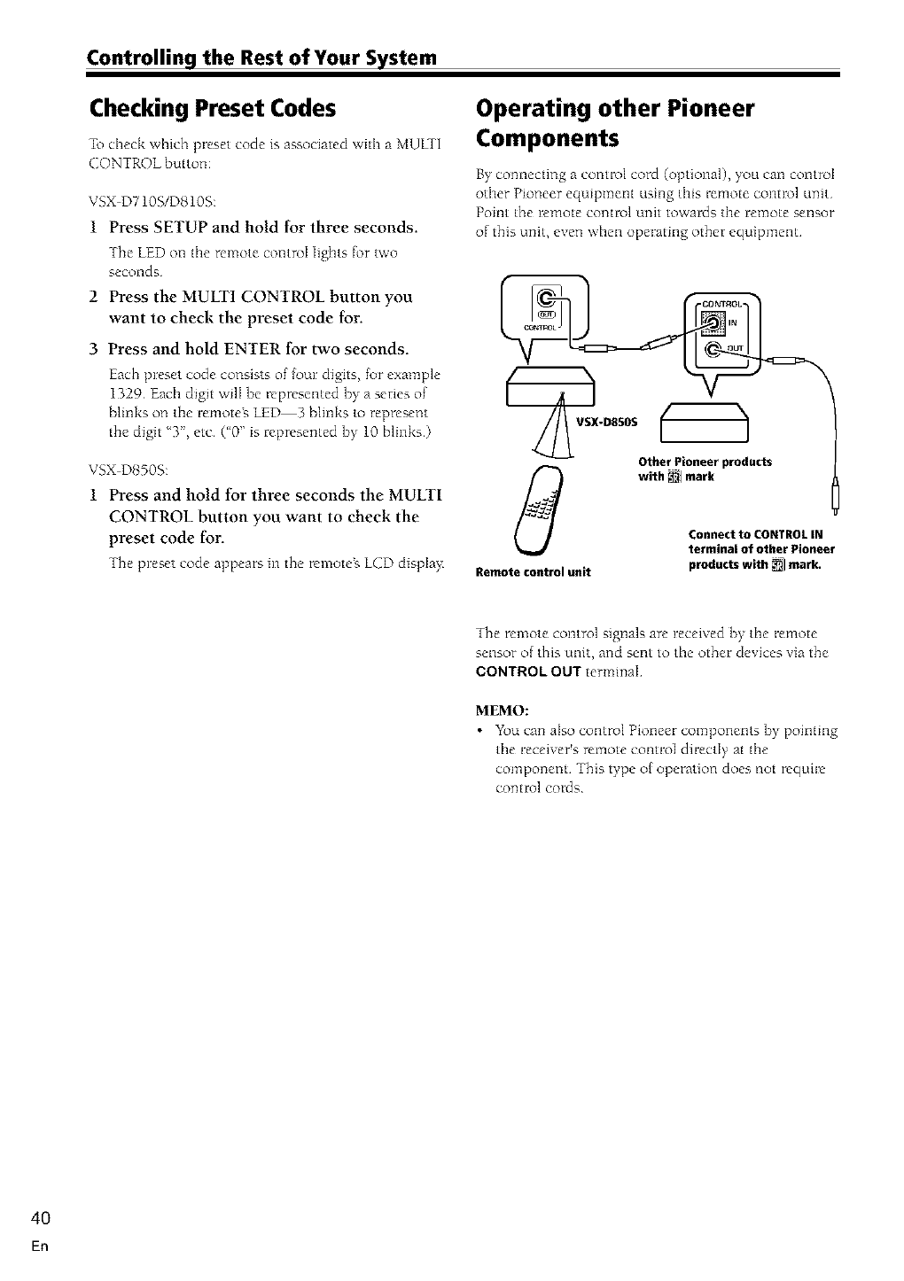
Controlling the Rest of Your System
Checking Preset Codes
To check which preset code is associated with a MUITI
CONTROL button:
VSX D710S/D810S:
1 Press SETUP and hold for three seconds.
The LED on tile remote control lights for two
seconds
2 Press the MULTI CONTROL button you
want to check the preset code tor.
3 Press and hold ENTER for two seconds.
Each preset code co_sists of four digtts, for example
1329 Each digit will be mpresemed by a series of
blinks on the remoteg LED 3 blinks to Bepresent
the digit '3"_ etc ('0" is represented by 10 blinks)
VSXD8505:
1 Press and hold for three seconds the MULTI
CONTROL button you want to check the
preset code for.
The preset code appears ill the remote_ LCDdispla),
Operating other Pioneer
Components
By comlecting a control cord (optional), you can control
other Pioneer equipment using this Bemote control unit
Point the remote control unit towards the remote sensor
of this unit, even when operating other equipment
Other Pioneer products
with _1 mark
Connect to CONTROL IN
termlnal of other Pioneer
products with _1 mark.
Remote control unit
The remote control signals are received by the remote
sensor of this unit, and sent to the other devices via the
CONTROL OUT terminaI
MEMO:
•YZ_ucan aIso control Pioneer components by pointing
the receiver's remote control directly at the
component This type of operation does not require
control cords
4O
En
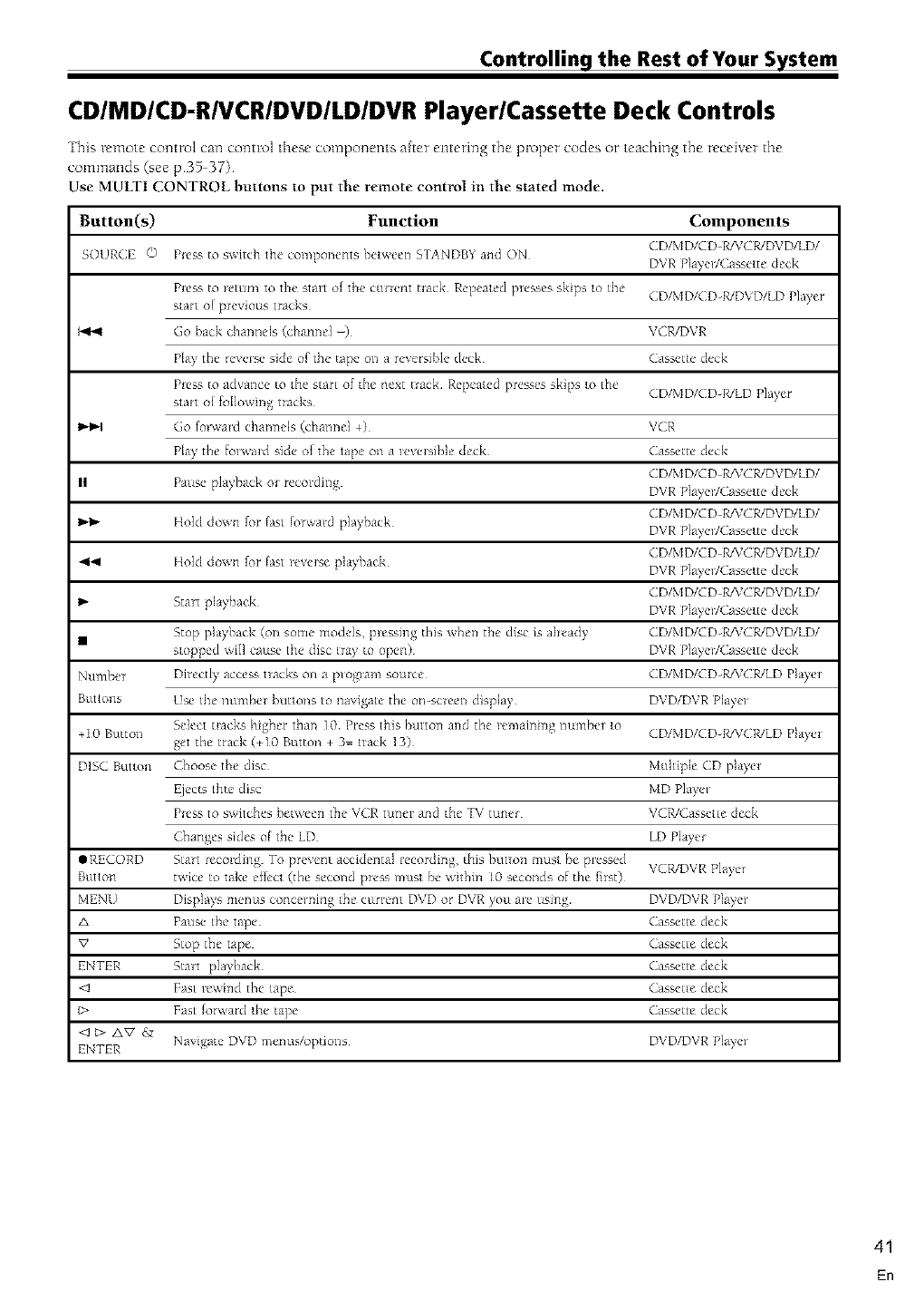
Controlling the Rest of Your System
CDIMDICD-RIVCRIDVDILDIDVR Player/Cassette Deck Controls
This remote comro] can comro] tlnese compotlems after entering the proper codes or teaching the receiver the
commands (see p35 37)
Use MULTI CONTROL buttons to put the remote control in the stated mode.
Button(s) Function Components
( D/MDICD R/VCR/DVD/LD/
SOURCE O P_e_-.to s_ itch the components hd_e_11 ST_NDB_ and ON DVR Pla)e_/(assdte deck
P_ess to _eturn to the st,m of the cuHent uack Repeald p_esses skips Io the (D/MD/(D-R/D_D/LD Pla_er
sla_l o[ p_evious tracks
I_ Go hack channds (channel -) V(R/DVR
Pla? the reverse side of the tape o1_a rexersihle deck ( assetle deck
P_ess to advm_ce to 1he s_art of the next uack Repealed presses skips Io the
sla_l ol follox ing tracks (D/MD/CD-R/LD Pla}er
I,,'_,-I Go fo/wald chamlels (channel +) VCR
Play the fo_x'alcl side o{ the tape on a _evelsihle deck ( asseue deck
( D/MD/CD R/VCR/DVD/LD/
II Pause pla) back o_ recoidillg DVR Pla}el/(assdte deck
( D/MD/CD R/VCR/DVD/LD/
Hokl down for lasl Iorwald pla)back DVR Pla}el/(assdte deck
( D/MD/CD R/VCR/DVD/LD/
4_ Hokl down for lasl _e_e_se pla}hack DVR Pla}e_/(assdte deck
( D/MD/CD R/VCR/DVD/LD/
Stair pla}hack DVR Pla)e_/(asselte deck
• Stop playback (on some models, plessing this xhel_ the disc is already (D/MD/CD-R/VCWDVD/LD/
sloppd will cause the disc nay to open) DVR Pla?el/( assdte deck
Numhel Directly access hacks on a p_og_am somce (D/MD/CD-R/V(WLD Playm
Buttons Use the numbel hutlons to na_igale the on-sc_eel_ display DVD/DVR Pla}e_
Select t_acks higher than 10 Press this butto_ m_d the _emaini_g lmmbm [o (D/MD/CD-R/V(R/LD Pla)'m
+10 Buttol_ get the track (+10 Button + 3= hack 13)
D1S( Buuon Choose the disc Multiple (D pla)'e_
Ejecls thte disc MD Pla}e/
P_ess to s_ itches hetwee_ the V(R tuf_m and the TV tuf_e_ VCR/( asselte deck
Changes sides ol the LD LD Pla}el
@RECORD Strut *eco_ding To prexent accidental _ecording, this hLitlOnm_ts{ be p_essed
Button t,_'ice to take eifecl (the second press musl be \ithin [0 seconds of the filst) VCWDVR Pla}e/
NtENU Displa}s menus concerning the cunent DVD or DVR )ou a_e using DVD/DVR Pla)e_
A Pause the tape ( assette deck
V Stop the tape (assette deck
ENTER Start pla)back (asseue deck
<J Fast _e_i_cl the tape ( asseue deck
t> Fast forward _he tape ( asseue deck
ENTER Navigate DVD menus/option,s DVD/DVR Pla)el
41
En
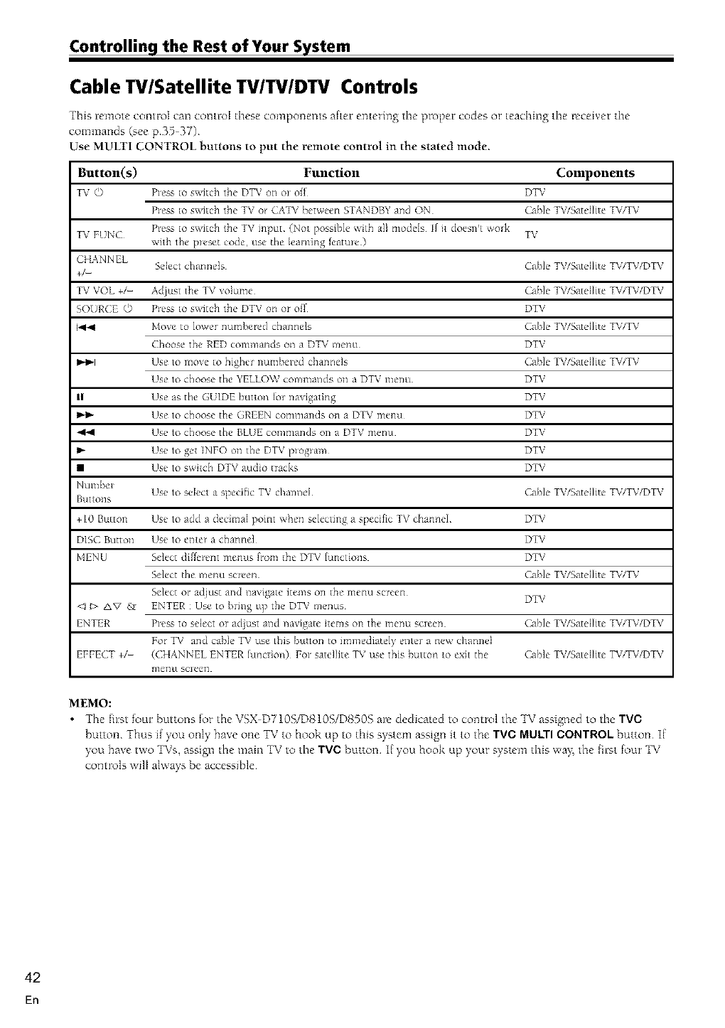
Controlling the Rest of Your System
Cable TV/Satellite Tv/'rV/DTV Controls
This remote control can control these componems after entering the proper codes or teaching the receiver the
commands (see p35 37)
Use MULTI CONTROL Buttons to put the remote control in the stated mode.
Button(s) Function Components
TV O P]ess to switch the DTV on o_ of_ DTV
P_ess to switch the TV o_ CATV bet_een STANDBY ,rod ON Cable TV/S,_tellite TV/TV
TV FUN( P_ess to switch the TV input (Nol possible _ith all models If it doeslft wod¢ TV
with the p_eset cocle, use the [earning leatme )
CHANNEL Select channels Cable TV/Satellite TV/TV/DTV
+/-
TV VOL +/- Adiust the TV volume Cable TV/Satellite TV/TV/DTV
SOlJR( E O P]css to switch the DTV on or oil DTV
I<l_l Move to lower numbered channels Cable TV/Satellite TV/TV
Choose the RED commands on a DTV menu DTV
I_m,-I Use to move to higher numbered channels Cable TV/Satdlite TV/TV
Use to choose the YELLO_ commands on a DTV me_J DTV
II Use as the GUIDE bution lot navigating DTV
Use to choose the GREEN commands on a DTV menu DTV
_l_ Use to choose the BEUE commands on a DTV menu DTV
I_ Use to get 1NFO on the DTV p_og_am DTV
• Use to switch DTV audio tracks DTV
Number Use to select a specific TV channel Cable TV/Satellite TV/TV/DTV
gLJttO;lS
+10 Button Use to add a decimal point when selecting a specific TV channel DTV
DISC Button Use to e_e_ a channel DTV
MENU Select di%_cnt menus [rom _he DTV lunctions DTV
Select the menu screen Cable TV/Satellite TV/TV
Select or at!just and navigate items on the menu screen DTV
<J I> AV & ENTER : Use to bring up the DTV menus
ENTER P_css to select or adiust and navigate items on the menu screen Cable TV/Satellite TV/TV/DTV
For TV and cable TV use this button to immediately enter a new channel
EFFECT +/- (CHANNEL ENTER hmction) Fo_ satellite TV use this button _oexit the Cable TV/Satellite TV/TV/DTV
menu sclee/]
MEMO:
•The first fore: buttons for the VSX D710S/D810S/D8505 are dedicated to control the TV assigned to the TVC
Button Thu _,ff)<_u onl)_hm,_ one TV 1ohook up to this _,yr_,temassign1it 1othe TVC MULTI CONTROL button K
_ou hae t\_o TVs, assign the mare TV to the TVC button If you hook up _our s_stem this \vay_the first four TV
contrt_ls wflI aBvays be accessible
42
En
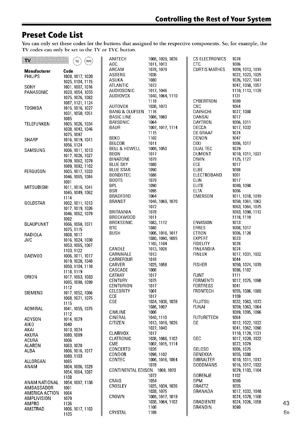
Controlling the Rest of Your System
Preset Code List
You can only set these codes for the buttons that assigned to the respective components. So, tbr exaInple, the
TV codes can only be set to the TV or 1WC button.
@ @
Manufact.rer Code
PHILIPS I008,1017,1020
I02R, 110_ 1115
SONY 1001,1007,1016
PANASONIC 1023,1054,1055
1075,1070,1002
1087,1121,1124
TOSHIBA 1015,1016,1027
1031,1050,1051
1085
TELEFUNKEN I005,I026,I034
1038,1042,1040
1075,1097
SHARP 1016,1019,1041
1056,1124
SAMSUNG 1006,1011,1013
1017,1026,1027
1039,1062,1079
1089,1092,1102
FERBUSON 1005,1017,1033
1046,1065,1084
1081
MITSUBISHI 1011,1016,1041
1045,1049,1062
1114
BOLDSTAR 1002,1011,1013
1017,1019,1026
1046,1062,1079
1082
BLAUPUNKT 1086,1066,1071
1075,1115
RADIOLA 1008,1017
JVC 1016,1024,1030
1053,1065,1067
1103,1122
DAEWO0 1006,1011,1017
1019,1026,1040
1050,1104,1110
1118,1119
ORION 1017,1063,1083
1085,1096,1099
1112
SIEMENS 1017,1052,1066
1088,1071,1075
1115
ADMIRAL 1041,1055,1075
1112
ADYSON 1014,1079
AIK0 1040
AKAI 1013,1074
AKURA 1080,1069
ACURA 1006
ALARBN 1083,1076
ALBA I006,1016,1017
1080,1103
ALLORGAN 1085
ANAM 1004,1000,1029
1054,1064,1087
1108
ANAM NATIONAL 1054,I087, 1108
AMBASSADOR 1081
AMERICA ACTION 1084
AMPLIVISION 1079
AMPRO 1126
AMSTRAD 1006,1017,1103
1105
ANITECH 1006,1029,1030
AOC 1011,1013
ARCAM 1070,1079
ASBERB 1030
ASUKA 1080
ATLANTIC 1073
AUDIOSRNIC 1017,1046
AUDIOVOX 1040,1084,1110
1118
AUTOVOX 1036,1073
BANG&OLUFSEN 1116
BASIC LINE 1006,1080
BAYSONIC 1064
BAUR 1007,1017,1114
1115
BEKO 1102
BELCRR 1011
BELL& HOWELL 1009,1050
BEON 1017
BINATONE 1079
BLUESKY 1080
BLUESTAR 1090
BONDSTEC 1086
BOOTS 1079
BPL 1090
BSR 1095
BRADFORD 1064
BRANDT 1046,1069,1070
1072
BRITANNIA 1078
BRRCKWOOD 1011
BRRKSONIC 1083,1112
BTC 1080
BUSH 1000,1018,1017
1080,1080,1095
1103,1104
CANDLE 1013,1026
CARNIVALE 1013
CARREFOUR 1016
CARVER 1025,1058
CASCADE 1006
CATHAY 1017
CENTURY 1075
CENTURION 1017
CELEBRITY 1001
CCE 1017
CBE 1034,1036,1038
1086,1097
ClMLINE 1006
ClNERAL 1040,1110
CITIZEN 1013,1019,1026
1027,1040
CLARIVOX 1017
CLATRONIC 1036,1086,1102
CME 1007,1015,1114
CONCERTO 1026
CONDOR 1098,1102
CONTEC 1006,1016,1064
1070
CONTINENTALEDISON 1069,1070
1072
CRAIG 1054
CROSLEY 1025,1034,1036
1030,1075
CROWN 1006,1017,1019
1036,1084,1102
1106
CRYSTAL 1109
CSELECTRONICS 1078
CTC 1086
CURTISMATHES 1009,1013,1019
1022,1023,1025
1026,1027,1041
1047,1050,1057
1110,1113,1129
1131
CYBERTRON 1080
CXC 1064
DAINICHI 1077,1080
DANSAI 1017
DAYTRON 1006,1011
DECCA 1017,1032
DE BRAAF 1074
DENON 1047
DIXI 1006,1017
DUALTEC 1079
DUMONT 1010,1011,1031
DWlN 1125,1127
ECE 1017
ELBE 1088
ELECTROBAND 1001
ELIN 1017
ELITE 1080,1098
ELTA 1006
EMERSON 1011,1018,1019
1050,1061,1082
1063,1064,1075
1083,1090,1112
1118,1119
ENVISION 1013
ERRES 1008,1017
ETRON 1006,1120
EXPERT 1073
FIDELITY 1078
FINLANDIA 1074
FINLUX 1017,1031,1032
1044
FISHER 1050,1074,1079
1096,1102
FLINT 1111
FORMENTI 1017,1075,1098
FORTRESS 1041
FRONTECH 1055,1086,1089
1109
FUJITSU 1032,1063,1073
FUNAI 1059,1063,1064
1089,1095,1096
FUTURETECH 1064
BE 1012,1022,1023
1041,1062,1090
1110,1129,1131
6EC 1017,1020,1032
1072,1079
6ELOSO 1006,1075
6ENEXXA 1055,1080
BIBRALTER 1010,1011,1013
600DMANS 1016,1017,1032
1079,1103,1104
BORENJE 1102
6PM 1080
6RAETZ 1055
GRANADA 1017,1032,1048
1074,1079,1100
BRADIENTE 1024,1026,1058
BRANDIN 1090 43
En
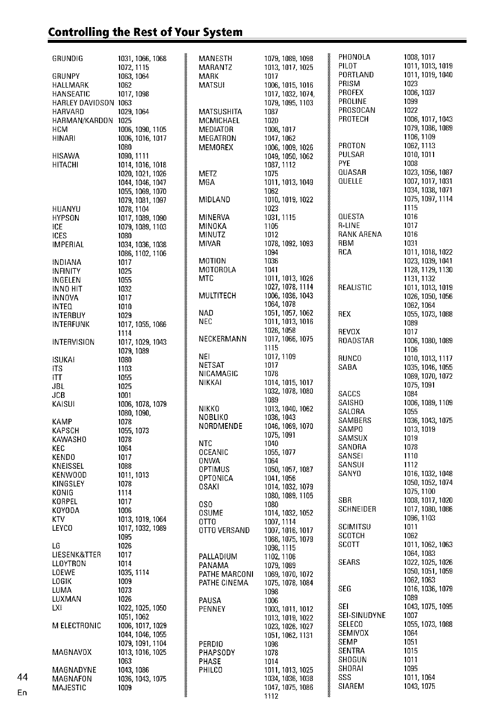
Controlling the Rest of Your System
44
En
ORUNDIO 1031,1066,1066
1072,1115
ORUNPY 1063,1064
HALLMARK 1062
HANSEATIC 1017,1098
HARLEYDAVIDSDN 1063
HARVARD 1029,1064
HARMAN/KARDDN 1025
HCM 1006,1090,1105
HINARI 1006,1016,1017
1080
HISAWA 1090,1111
HITACHI 1014,1016,1018
1020,1021,1026
1044,1046,1047
1055,1069,1070
1079,1081,1097
HUANYU 1078,1104
HYPSDN 1017,1089,1090
ICE 1079,1089,1103
ICES 1080
IMPERIAL 1034,1036,1036
1086,1102,1106
INDIANA 1017
INFINITY 1025
INGELEN 1055
INNO HIT 1032
INNOVA 1017
INTEQ 1010
INTERBUY 1029
INTERPDNK 1017,1055,1086
1114
INTERVISION 1017,1029,1043
1079,1089
ISUKAt 1080
ITS 1103
ITT 1055
JBL 1025
JCO 1001
KAISDI 1006,1078,1079
1060,1090,
KAMP 1076
KAPSCH 1055,1073
KAWASHO 1076
KEC 1064
KENDO 1017
KNEISSEL 1088
KENWOOD 1011,1013
KINOSLEY 1078
KONIO 1114
KORPEL 1017
KOYODA 1006
KTV 1013,1019,1064
LEYCO 1017,1032,1089
1095
LO 1026
LIESENK&TTER 1017
LLOYTRON 1014
LOEWE 1035,1114
LOOIK 1009
LUMA 1073
LUXMAN 1026
LXI 1022,1025,1050
1051,1062
M ELECTRONIC 1006,1017,1029
1044,1046,1055
1079,1091,1104
MAONAVOX 1013,1016,1025
1063
MAGNADYNE 1043,1086
MAONAFON 1036,1043,1075
MAJESTIC 1009
MANESTH
MARANTZ
MARK
MATSDI
MATSUSHITA
MCMICHAEL
MEDIATOR
MEOATRON
MEMOREX
METZ
MOA
MIDLAND
MINERVA
MINOKA
MINUTZ
MIVAR
MOTION
MOTOROLA
MTC
MULTITECH
NAD
NEC
NECKERMANN
NEI
NETSAT
NICAMAOIC
NIKKAI
NIKKO
NOBLIKO
NORDMENDE
NTC
OCEANIC
0NWA
0PTIMDS
0PTONICA
OSAKI
0SO
0SUME
OTTO
OTTOVERSAND
PALLADIUM
PANAMA
PATHEMARCONI
PATHECINEMA
PAUSA
PENNEY
PERDIO
PHAPSODY
PHASE
PHILCO
1079,1089,1098
1013,1017,1025
1017
1006,1015,1016
1017,1032,1074,
1079,1095,1103
1087
1020
1006,1017
1047,1062
1006,1009,1026
1049,1050,1062
1067,1112
1075
1011,1013,1049
1062
1010,1019,1022
1023
1031,1115
1105
1012
1076,1092,1093
1094
1036
1041
1011,1013,1026
1027,1078,1114
1006,1036,1043
1064,1078
1051,1057,1062
1011,1013,1016
1026,1058
1017,1066,1075
1115
1017,1109
1017
1078
1014,1015,1017
1032,107&1080
1089
1013,1040,1062
1036,1043
1046,1069,1070
1075,1091
1040
1055,1077
1064
1050,1057,1087
1041,1056
1014,1032,1079
1060,1089,1105
1080
1014,1032,1052
1007,1114
1007,1016,1017
1066,1075,1079
1096,1115
1102,1106
1079,1089
1069,1070,1072
1075,107&1084
1096
1006
1003,1011,1012
1013,1019,1022
1023,1026,1027
1051,1062,1131
1096
1078
1014
1011,1013,1025
1034,1036,1038
1047,1075,1086
1112
PHONOLA
PILOT
PORTLAND
PRISM
PROFEX
PROLINE
PROSOCAN
PROTECH
PROTON
PULSAR
PYE
QUASAR
QUELLE
QUESTA
R-LINE
RANK ARENA
RBM
RCA
REALISTIC
REX
REVOX
ROADSTAR
RUNCO
SABA
SACCS
SAISHO
SALORA
SAMBERS
SAMPO
SAMSUX
SANDRA
SANSEI
SANSDI
SANYO
SBR
SCHNEIDER
SClMITSD
SCOTCH
SCOTT
SEARS
SE6
SEI
SEI-SINUDYNE
SELECO
SEMIVOX
SEMP
SENTRA
SHOGUN
SHORAI
SSS
SIAREM
1008,1017
1011,1013,1019
1011,1019,1040
1023
1006,1037
1099
1022
1006,1017,1043
1079,1066,1089
1106,1109
1062,1113
1010,1011
1008
1023,1056,1087
1007,1017,1031
1034,1036,1071
1075,1097,1114
1115
1016
1017
1016
1031
1011,1016,1022
1023,1039,1041
1128,1129,1130
1131,1132
1011,1013,1019
1026,1050,1056
1062,1064
1055,1073,1088
1089
1017
1006,1060,1089
1106
1010,1013,1117
1035,1046,1055
1069,1070,1072
1075,1091
1084
1006,1069,1109
1055
1036,1043,1075
1013,1019
1019
1078
1110
1112
1016,1032,1048
1050,1052,1074
1075,1100
1008,1017,1020
1017,1060,1086
1096,1103
1011
1062
1011,1062,1063
1064,1063
1022,1025,1026
1050,1051,1059
1062,1063
1016,1036,1079
1089
1043,1075,1095
1007
1055,1073,1086
1064
1051
1015
1011
1095
1011,1064
1043,1075
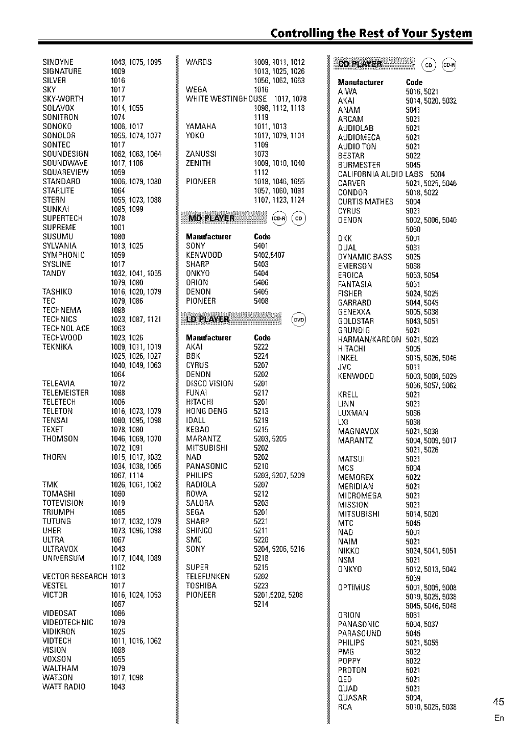
Controlling the Rest of Your System
SINDYNE 1043,1075,1095
SIGNATURE 1009
SILVER 1016
SKY 1017
SKY-WORTH 1017
SDLAVDX 1014,1055
SDNITRDN 1074
SDNOKO 1006,1017
SDNOLDR 1055,1074,1077
SDNTEC 1017
SDUNDESIDN 1062,1063,1064
SDUNDWAVE 1017,1106
SQUAREVIEW 1059
STANDARD 1006,1079,1080
STARLITE 1064
STERN 1055,1073,1088
SUNKAI I095, 1099
SUPERTECH 1078
SUPREME 1001
SUSUMU 1080
SYLVANIA 1013,1025
SYMPHONIC 1059
SYSLINE 1017
TANDY 1032,1041,1055
1079,1080
TASHIKO 1016,1020,1079
TEC 1079,1086
TECHNEMA 1098
TECHNICS 1023,1087,1121
TECHNOLACE 1063
TECHWOOD 1023,1026
TEKNIKA 1009,1011,1019
1025,1026,1027
1040,1049,1063
1064
TELEAVlA 1072
TELEMEISTER 1098
TELETECH 1006
TELETON 1016,1073,1079
TENSAI 1060,1095,1098
TEXET 1078,1080
THOMSON 1046,1069,1070
1072,1091
THORN 1015,1017,1032
1034,1038,1065
1067,1114
TMK 1026,1061,1062
TOMASHI 1090
TOTEVlSION 1019
TRIUMPH 1065
TUTUND 1017,1032,1079
UHER 1073,1096,1098
ULTRA 1067
ULTRAVOX 1043
UNIVERSUM 1017,1044,1089
1102
VECTORRESEARCH1013
VESTEL 1017
VICTOR 1016,1024,1053
1087
VIDEOSAT 1086
VIDEOTECHNIC 1079
VIDIKRON 1025
VIDTECH 1011,1016,1062
VISION 1098
VOXSON 1055
WALTHAM 1079
WATSON 1017,1098
WATT RADIO 1043
WARDS I009, 1011,1012
I013, 1025,1026
I056, 1062,1063
WEDA 1016
WRITE WESTINDHOUSE 1017,1078
1098,1112,1118
1119
YAMAHA I011, 1013
YOKO 1017,1079,1101
1109
ZANUSSI 1073
ZENITH 1009,1010,1040
1112
PIONEER 1018,1046,1055
1057,1060,1091
1107,1123,1124
Manufacturer Cede
SONY 5401
KENWOOD 5402,5407
SHARP 5403
ONKYO 5404
ORION 5406
DENON 5405
PIONEER 5408
Manufacturer Code
AKAI 5222
BBK 5224
CYRUS 5207
DENON 5202
DISCOVISION 5201
FUNAI 5217
HITACHI 5201
ROND DEND 5213
IDALL 5219
KEBAO 5215
MARANTZ 5203,5205
MITSUBISHI 5202
NAD 5202
PANASONIC 5210
PHILIPS 5203,5207,5209
RADIOLA 5207
ROWA 5212
SALORA 5203
SEDA 5201
SHARP 5221
SHINCO 5211
SMC 5220
SONY 5204,5206,5216
5218
SUPER 5215
TELEFUNKEN 5202
TOSHIBA 5223
PIONEER 5201,5202,5208
5214
Manufacturer Code
AIWA 5016,5021
AKAI 5014,5020,5032
ANAM 5041
ARCAM 5021
AUDIOLAB 5021
AUDIOMECA 5021
AUDIO TON 5021
BESTAR 5022
BURMESTER 5045
CALIFORNIAAUDIO LABS 5004
CARVER 5021,5025,5046
CONDOR 5018,5022
CURTISMATHES 5004
CYRUS 5021
DENON 5002,5006,5040
5060
DKK 5001
DUAL 5031
DYNAMIC BASS 5025
EMERSON 5038
EROICA 5053,5054
FANTASIA 5051
FISHER 5024,5025
6ARRARD 5044,5045
6ENEXXA 5005,5038
6OLDSTAR 5043,5051
DRUNDID 5021
HARMAN/KARDON 5021,5023
HITACHI 5005
INKEL 5015,5026,5046
JVC 5011
KENWOOD 5003,5008,5029
5056,5057,5062
KRELL 5021
LINN 5021
LUXMAN 5036
LXI 5038
MADNAVOX 5021,5038
MARANTZ 5004,5009,5017
5021,5026
MATSUI 5021
MCS 5004
MEMOREX 5022
MERIDIAN 5021
MICROMEBA 5021
MISSION 5021
MITSUBISHI 5014,5020
MTC 5045
NAD 5001
NAIM 5021
NIKKO 5024,5041,5051
NSM 5021
ONKYO 5012,5013,5042
5059
OPTIMUS 5001,5005,5008
5019,5025,5038
5045,5046,5048
ORION 5061
PANASONIC 5004,5037
PARASOUND 5045
PHILIPS 5021,5055
PMD 5022
POPPY 5022
PROTON 5021
QED 5021
QUAD 5021
QUASAR 5004,
RCA 5010,5025,5038 45
En
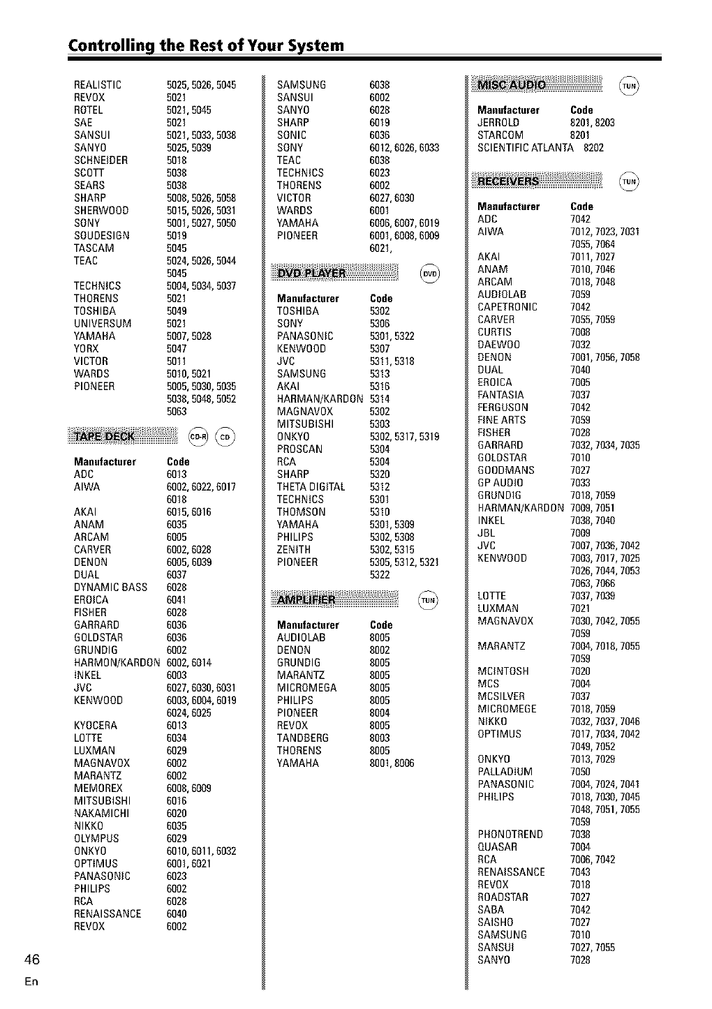
Controlling the Rest of Your System
46
En
REALISTIC 5625,5026,5045
REVOX 5021
ROTEL 5621,5045
SAE 5021
SANSUI 5621,5033,5036
SANYO 5625,5039
SCHNEIDER 5616
SCOTT 5636
SEARS 5636
SHARP R666,5026,5058
SHERWOOD 5615,5026,5031
SONY 5661,5027,5050
SOUDESIBN 5619
TASCAM 5045
TEAC 5624,5026,5044
5645
TECHNICS 5604,5034,5037
THORENS 5621
TOSHIBA 5649
UNIVERSUM 5021
YAMAHA 5607,5028
YORX 5047
VICTOR 5611
WARDS 5610,5021
PIONEER 5605,5036,5035
5036,5048,5052
5663
Manufacturer Code
ADC 6013
AIWA 6002,6022,6017
6616
AKAI 6615,6016
ANAM 6035
ARCAM 6005
CARVER 6602,6028
DENON 6605,6039
DUAL 6037
DYNAMIC BASS 6626
EROICA 6041
FISHER 6628
BARRARD 6036
BOLDSTAR 6036
BRUNOIB 6002
HARMON/KARDON 6662,6014
INKEL 6003
JVC 6627,6036,6031
KENWOOD 6663,6004,6619
6624,6025
KYOCERA 6013
LOTTE 6034
LUXMAN 6029
MABNAVOX 6002
MARANTZ 6002
MEMOREX 6666,6009
MITSUBISHI 6016
NAKAMICHI 6620
NIKKO 6035
OLYMPUS 6629
ONKYO 6610,6011,6032
OPTIMUS 6661,6021
PANASONIC 6023
PHILIPS 6002
RCA 6626
RENAISSANCE 6640
REVOX 6002
SAMSUNB 6638
SANSUI 6002
SANYO 6628
SHARP 6619
SONIC 6036
SONY 6612,6026,6033
TEAC 6636
TECHNICS 6023
THORENS 6002
VICTOR 6627,6036
WARDS 6001
YAMAHA 6606,6007,6019
PIONEER 6601,6008,6009
6621,
Manufacturer Code
TOSHIBA 5302
SONY 5306
PANASONIC 5301,5322
KENWOOD 5307
JVC 5311,5318
SAMSUNB 5313
AKAI 0316
HARMAN/KARDON 5314
MAB NAVOX 5302
MITSUBISHI 5303
ONKYO 5362,5317,5319
PROSCAN 5304
RCA 5304
SHARP 5320
THETADIGITAL 5312
TECHNICS 5301
THOMSON 5310
YAMAHA 5301,5309
PHILIPS 5362,5308
ZENITH 5302,5315
PIONEER 5305,5312,5321
5322
Manufacturer Code
AUBIOLAB 8005
DENON 8002
BRUNOIB 8005
MARANTZ 8005
MICROMEOA 8065
PHILIPS 8605
PIONEER 8004
REVOX 8005
TANDBERB 8003
THORENS 8005
YAMAHA 8661,6006
Manufacturer Code
JERROLO 8201,6203
STARCOM 8201
SCIENTIFICATLANTA 8202
Manufacturer Code
ADC 7042
AIWA 7012,7023,7031
7055,7064
AKAI 7011,7027
ANAM 7016,7046
ARCAM 7018,7046
AUOIOLAB 7059
CAPETRONIC 7042
CARVER 7055,7059
CURTIS 7006
DAEWOO 7032
DENON 7001,7056,7058
DUAL 7046
EROICA 7005
FANTASIA 7037
FEROOSON 7042
FINEARTS 7059
FISHER 7028
BARRARD 7032,7034,7035
BOLOSTAR 7016
BOODMANS 7027
BP AUDIO 7033
BRONDIB 7016,7059
HARMAN/KARDON 7009,7051
INKEL 7038,7040
JBL 7009
JVC 7007,7036,7042
KENWOOD 7003,7017,7025
7026,7044,7053
7063,7066
LOTTE 7037,7039
LUXMAN 7021
MABNAVOX 7036,7042,7055
7059
MARANTZ 7004,7016,7055
7059
MClNTOSH 7026
MCS 7004
MCSILVER 7037
MICROMEGE 7016,7059
NIKKO 7032,7037,7046
OPTIMUS 7017,7034,7042
7049,7052
ONKYO 7013,7029
PALLADIUM 7056
PANASONIC 7004,7024,7041
PRILIPS 7018,7030,7045
7048,7051,7055
7059
PHONOTREND 7038
QUASAR 7004
RCA 7006,7042
RENAISSANCE 7043
REVOX 7016
ROADSTAR 7027
SABA 7042
SAISHO 7027
SAMSUNG 7016
SANSUI 7027,7055
SANY0 7028
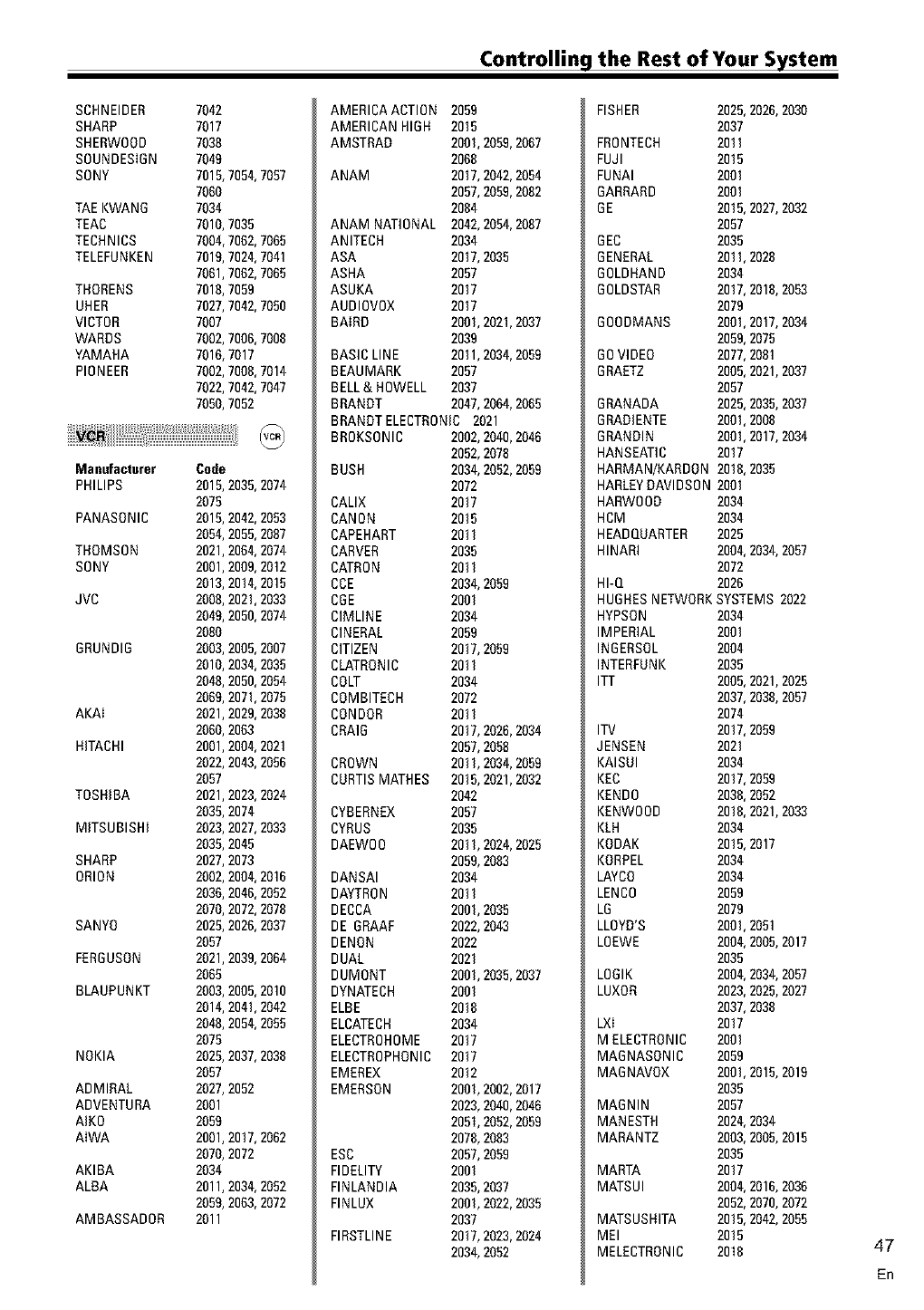
Controlling the Rest of Your System
SCHNEIDER
SHARP
SHERWOOD
SOUNDESIDN
SONY
TAE KWANO
TEAC
TECHNICS
TELEFUNKEN
THORENS
UHER
VICTOR
WARDS
YAMAHA
PIONEER
Mal|ufact.rer
PHILIPS
PANASONIC
THOMSON
SONY
JVC
ORUNDIO
AKAI
HITACHI
TOSHIBA
MITSUBISHI
SHARP
ORION
SANYO
FERGUSON
BLAUPUNKT
NOKIA
ADMIRAL
ADVENTURA
AIKO
AIWA
AKIBA
ALBA
AMBASSADOR
7042
7017
7038
7049
7015,7054,7057
7060
7034
7010,7035
7004,7062,7065
7019,7024,7041
7061,7062,7065
7018,7059
7027,7042,7050
7007
7002,7006,7008
7016,7017
7002,7008,7014
7022,7042,7047
7050,7052
Code
2015,2035,2074
2075
2015,2042,2053
2054,2055,2087
2021,2064,2074
2001,2009,2012
2013,2014,2015
2008,2021,2033
2049,2050,2074
2080
2003,2005,2007
2010,2034,2035
2048,2050,2054
2069,2071,2075
2021,2029,2038
2060,2063
2001,2004,2021
2022,2043,2056
2057
2021,2023,2024
2035,2074
2023,2027,2033
2035,2045
2027,2073
2002,2004,2016
2036,2046,2052
2070,2072,2078
2025,2026,2037
2057
2021,2039,2064
2065
2003,2005,2010
2014,2041,2042
2048,2054,2055
2075
202R,2037,2038
2057
2027,2052
2001
2059
2001,2017,2062
2070,2072
2034
2011,2034,2052
2059,2063,2072
2011
AMERICA ACTION 2059
AMERICAN HIGH 2015
AMSTRAD 2001,2059,2067
2068
ANAM 2017,2042,2054
2057,2059,2082
2084
ANAM NATIONAL 2042,2054,2087
ANITECH 2034
ASA 2017,2035
ASHA 2057
ASUKA 2017
AUDIOVOX 2017
BAIRD 2001,2021,2037
2039
BASIC LINE 2011,2034,2059
BEAUMARK 2057
BELL& HOWELL 2037
BRANDT 2047,2064,2065
BRANOT ELECTRONIC 2021
BROKSONIC 2002,2040,2046
2052,2078
BUSH 2034,2052,2059
2072
CALIX 2017
CANON 2015
CAPEHART 2011
CARVER 2035
CATRON 2011
CCE 2034,2059
COE 2001
CIMLINE 2034
CINERAL 2059
CITIZEN 2017,2059
CLATRONIC 2011
COLT 2034
COMBITECH 2072
CONDOR 2011
CRAIG 2017,2026,2034
2057,2058
CROWN 201I, 2034,2059
CURTISMATHES 2015,2021,2032
2042
CYBERNEX 2057
CYRUS 2035
DAEWOO 2011,2024,2025
2059,2083
DANSAI 2034
DAYTRON 2011
DECCA 2001,2035
DE ORAAP 2022,2043
DENON 2022
DUAL 2021
DUMONT 2001,2035,2037
DYNATECH 2001
ELBE 2018
ELCATECH 2034
ELECTROHOME 2017
ELECTROPHONIC 2017
EMEREX 2012
EMERSON 2001,2002,2017
2023,2040,2046
2051,2052,2059
2078,2083
ESC 2057,2059
FIDELITY 2001
FINLANDIA 2035,2037
FINLUX 2001,2022,2035
2037
FIRSTLINE 2017,2023,2024
2034,2052
FISHER 2025,2026,2030
2037
FRONTECH 2011
FUJI 2015
FUNAI 2001
DARRARD 2001
DE 2015,2027,2032
2057
DEC 2035
GENERAL 2011,2028
DOLDHAND 2034
6OLDSTAR 2017,2018,2053
2079
6OODMANS 2001,2017,2034
2059,2075
60 VIDEO 2077,2081
DRAETZ 2005,2021,2037
2057
GRANADA 2025,2035,2037
DRAOIENTE 2001,2008
DRANOIN 2001,2017,2034
HANSEATIC 2017
HARMAN/KARDON 2018,2035
HARLEYOAVlDSON 2001
HARWOOD 2034
HCM 2034
HEADQUARTER 2025
HINARI 2004,2034,2057
2072
HI-Q 2026
HUGHESNETWORKSYSTEMS 2022
HYPSON 2034
IMPERIAL 2001
INDERSOL 2004
INTERPUNK 2035
ITT 2005,2021,2025
2037,2038,2057
2074
ITV 2017,2059
JENSEN 2021
KAISUI 2034
KEC 2017,2059
KENDO 2038,2052
KENWOOD 2018,2021,2033
KLH 2034
KODAK 2015,2017
KORPEL 2034
LAYCO 2034
LENCO 2059
LG 2079
LLOYD'S 2001,2051
LOEWE 2004,2005,2017
2035
LOOIK 2004,2034,2057
LUXOR 2023,2025,2027
2037,2038
LXI 2017
M ELECTRONIC 2001
MADNASONIC 2059
MADNAVOX 2001,2015,2019
2035
MAGNIN 2057
MANESTH 2024,2034
MARANTZ 2003,2005,2015
2035
MARTA 2017
MATSUI 2004,2016,2036
2052,2070,2072
MATSUSHITA 2015,2042,2055
MEI 2015
MELECTRONIC 2018 47
En
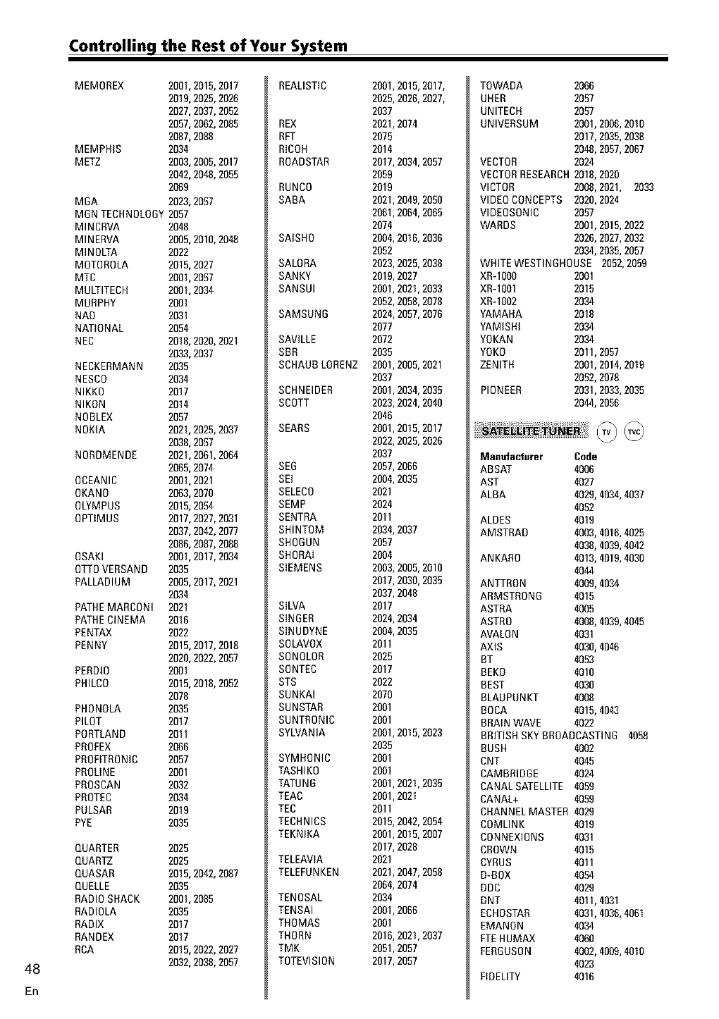
Controlling the Rest of Your System
48
En
MEMOREX 2001,2015,2017
2019,2025,2026
2027,2037,2052
2057,2062,2065
2087,2088
MEMPHIS 2034
METZ 2003,2005,2017
2042,2048,2059
2069
MOA 2023,2097
MBN TECHNOLOGY2057
MINCRVA 2048
MINERVA 2005,2010,2048
MINOLTA 2022
MOTOROLA 2015,2027
MTC 2001,2097
MULTITECH 2001,2034
MURPHY 2001
NAB 2031
NATIONAL 2054
NEC 2018,2020,2021
2033,2037
NECKERMANN 2035
NESCO 2034
NIKKO 2017
NIKON 2014
NOBLEX 2057
NOKIA 2021,2025,2037
2038,2097
NORDMENDE 2021,2061,2064
2065,2074
OCEANIC 2001,2021
OKANO 2063,2070
OLYMPUS 2015,2094
OPTIMUS 2017,2027,2031
2037,2042,2077
2086,2087,2068
OSAKI 2001,2017,2034
OTTOVERSAND 2035
PALLADIUM 2005,2017,2021
2034
PATHEMARCONI 2021
PATHECINEMA 2016
PENTAX 2022
PENNY 2015,2017,2016
2020,2022,2057
PERDIO 2001
PHILCO 2015,2018,2052
2078
PHONOLA 2035
PILOT 2017
PORTLAND 2011
PROFEX 2066
PROFITRONIC 2057
PROLINE 2001
PROSCAN 2032
PROTEC 2034
PULSAR 2019
PYE 2035
QUARTER 2025
QUARTZ 2025
QUASAR 2015,2042,2087
QUELLE 2035
RADIOSHACK 2001,2085
RADIOLA 2035
RADIX 2017
RANDEX 2017
RCA 2015,2022,2027
2032,2038,2057
REALISTIC
REX
RFT
RICOH
ROADSTAR
RUNCO
SABA
SAISHO
SALORA
SANKY
SANSUI
SAMSUN6
SAVlLLE
SBR
SCHAUBLORENZ
SCHNEIDER
SCOTT
SEARS
SEG
SEI
SELECO
SEMP
SENTRA
SHINTOM
SHOGUN
SHORN
SIEMENS
SILVA
SINGER
SINUDYNE
SOLAVOX
SONOLOR
SONTEC
STS
SUNKAI
SUNSTAR
SUNTRONIC
SYLVANIA
SYMHONIC
TASHIKO
TATUNG
TEAC
TEC
TECHNICS
TEKNIKA
TELEAVlA
TELEFUNKEN
TENOSAL
TENSAI
THOMAS
THORN
TMK
TOTEVISION
2001,2015,2017,
2025,2026,2027,
2037
2021,2074
2075
2014
2017,2034,2097
2059
2019
2021,2049,2090
2061,2064,2065
2074
2004,2016,2036
2052
2023,2025,2038
2019,2027
2001,2021,2033
2052,205&2078
2024,2057,2076
2077
2072
2035
2001,2005,2021
2037
2001,2034,2035
2023,2024,2040
2046
2001,2015,2017
2022,2025,2026
2037
2057,2066
2004,2035
2021
2024
2011
2034,2037
2057
2004
2003,2005,2010
2017,2030,2035
2037,2048
2017
2024,2034
2004,2035
2011
2025
2017
2022
2070
2001
2001
2001,2015,2023
2035
2001
2001
2001,2021,2035
2001,2021
2011
2015,2042,2094
2001,2015,2007
2017,2028
2021
2021,2047,2098
2064,2074
2034
2001,2066
2001
2016,2021,2037
2051,2057
2017,2057
TOWADA 2066
UHER 2057
UNITECH 2057
UNIVERSUM 2001,2006,2010
2017,2035,2038
2048,2057,2067
VECTOR 2024
VECTORRESEARCH2018,2020
VICTOR 2008,2021, 2033
VIDEO CONCEPTS 2020,2024
VlDEOSONIC 2097
WARDS 2001,2015,2022
2026,2027,2032
2034,2035,2057
WHITE WESTINGHOUSE 2052,2059
XR-10O0 2001
XR-10Ol 2015
XR-1002 2034
YAMAHA 2018
YAMISHI 2034
YOKAN 2034
YOKO 2011,2057
ZENITH 2001,2014,2019
2092,2076
PIONEER 2031,2033,2035
2044,2056
Ma.ufacturer Code
ABSAT 4006
AST 4027
ALBA 4029,4034,4037
4052
ALDES 4019
AMSTRAD 4003,4016,4025
4038,4039,4042
ANKARO 4013,4019,4030
4044
ANTTRON 4009,4034
ARMSTRONG 4015
ASTRA 4005
ASTRO 4008,4039,4045
AVALON 4031
AXIS 4030,4046
BT 4053
BEKO 4010
BEST 4030
BLAOPUNKT 4008
BOCA 4015,4043
BRAINWAVE 4022
BRITISHSKYBROADCASTING 4058
BUSH 4002
CNT 4045
CAMBRIDGE 4024
CANAL SATELLITE 4059
CANAL+ 4059
CHANNEL MASTER 4029
COMLINK 4019
CONNEXIONS 4031
CROWN 4015
CYRUS 4011
D-BOX 4094
DDC 4029
DNT 4011,4031
ECHOSTAR 4031,4036,4061
EMANON 4034
FTEHUMAX 4060
FERBUSON 4002,4009,4010
4023
FIDELITY 4016
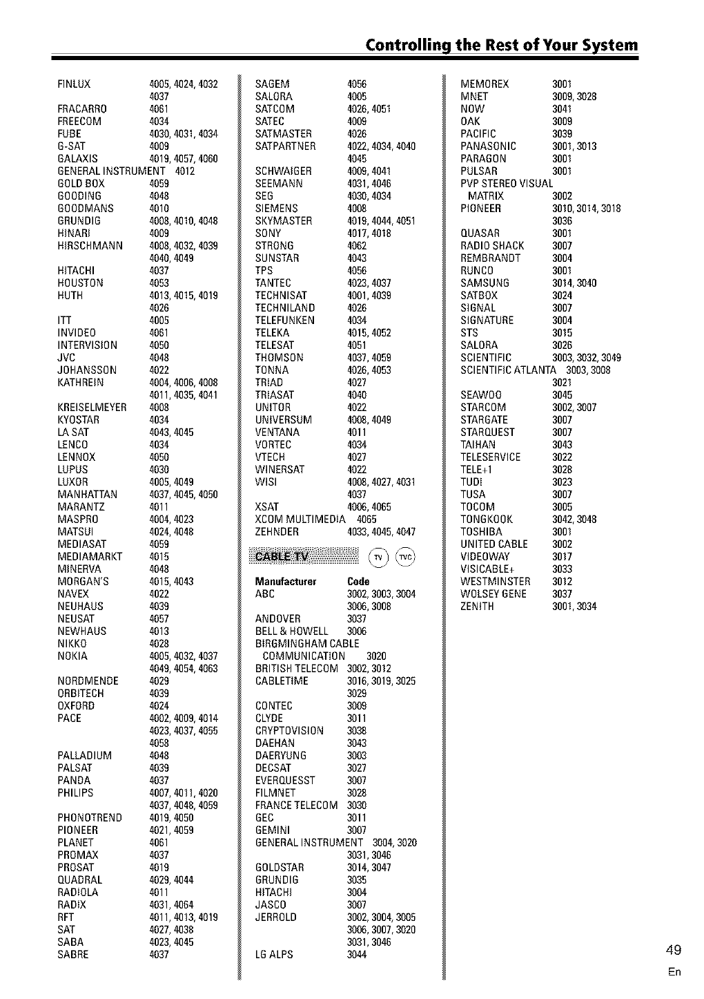
Controlling the Rest of Your System
FINLUX 4005,4024,4032
4037
FRACARR0 4061
FREECOM 4034
FUBE 4030,4031,4034
B-SAT 4009
6ALAXIS 4019,4097,4060
GENERALINSTRUMENT 4012
BOLDBOX 4059
600OIN6 4048
60GDMANS 4010
GRUNDIG 4008,4010,4048
HINARI 4009
HIRSCHMANN 4008,4032,4039
4040,4049
HITACHI 4037
HOUSTON 4053
HUTH 4013,4015,4019
4026
ITT 4005
INVIDEO 4061
INTERVISION 4050
JVC 4048
JGHANSSGN 4022
KATHREIN 4004,4006,4008
4011,4035,4041
KREISELMEYER 4008
KYOSTAR 4034
LASAT 4043,4045
LENCG 4034
LENNOX 4050
LUPUS 4030
LUXOR 4005,4049
MAN HATTAN 4037,4045,4050
MARANTZ 4011
MASPRO 4004,4023
MATSUI 4024,4048
MEDIASAT 4059
MEDIAMARKT 4015
MINERVA 4048
MORGAN'S 4015,4043
NAVEX 4022
NEUHAUS 4039
NEUSAT 4057
NEWHAUS 4013
NIKKO 4028
NOKIA 4005,4032,4037
4049,4054,4063
NORDMENDE 4029
0RBITECH 4039
OXFORD 4024
PACE 4002,4009,4014
4023,4037,4055
4058
PALLADIUM 4048
PALSAT 4039
PANDA 4037
PHILIPS 4007,401I, 4020
4037,4048,4059
PHGNGTREND 4019,4050
PIONEER 4021,4059
PLANET 4061
PROMAX 4037
PROSAT 4019
QUADRAL 4029,4044
RADIOLA 4011
RADIX 4031,4064
RFT 4011,4013,4019
SAT 4027,4038
SAGA 4023,4045
SABRE 4037
SAOEM 4056
SALORA 4005
SATCOM 4026,4051
SATEC 4009
SATMASTER 4026
SATPARTNER 4022,4034,4040
4045
SCHWAIGER 4009,4041
SEEMANN 4031,4046
SEG 4030,4034
SIEMENS 4008
SKYMASTER 4019,4044,4051
SONY 4017,4018
STRONG 4062
SUNSTAR 4043
TPS 4056
TANTEC 4023,4037
TECHNISAT 4001,4039
TECHNILAND 4026
TELEFUNKEN 4034
TELEKA 4015,4052
TELESAT 4051
THOMSON 4037,4059
TGNNA 4026,4053
TRIAD 4027
TRIASAT 4040
UNITOR 4022
UNIVERSUM 4008,4049
VENTANA 4011
VORTEC 4034
VTECH 4027
WINERSAT 4022
WlSI 4008,4027,4031
4037
XSAT 4006,4065
XCOM MULTIMEDIA 4065
ZEHNDER 4033,4045,4047
Ma.ufacturer Code
ARC 3002,3003,3004
3006,3008
ANDOVER 3037
BELL& HOWELL 3006
BIRBMINGHAM CABLE
COMMUNICATION 3020
BRITISHTELECOM 3002,3012
CABLETIME 3016,3019,3025
3029
CGNTEC 3009
CLYDE 3011
CRYPTGVlSIGN 3038
DAEHAN 3043
DAERYUNG 3003
DECSAT 3027
EVERQUESST 3007
FILMNET 3028
FRANCETELECOM 3030
6EC 3011
GEMINI 3007
GENERALINSTRUMENT 3004,3020
3031,3046
60LDSTAR 3014,3047
GRUNDIG 3035
HITACHI 3004
JASC0 3007
JERROLD 3002,3004,3005
3006,3007,3020
3031,3046
LGALPS 3044
MEMOREX 3001
MNET 3009,3028
NOW 3041
OAK 3009
PACIFIC 3039
PANASONIC 3001,3013
PARAGON 3001
PULSAR 3001
PVPSTEREOVISUAL
MATRIX 3002
PIONEER 3010,3014,3018
3036
QUASAR 3001
RADIOSHACK 3007
REMBRANDT 3004
RUNCO 3001
SAMSUNG 3014,3040
SATBOX 3024
SIGNAL 3007
SIGNATURE 3004
STS 3015
SALGRA 3026
SCIENTIFIC 3003,3032,3049
SCIENTIFICATLANTA 3003,3008
3021
SEAWGO 3045
STARCGM 3002,3007
STARBATE 3007
STARQUEST 3007
TAIHAN 3043
TELESERVICE 3022
TELE+I 3028
TUDI 3023
TUSA 3007
TOCOM 3005
TONGKOOK 3042,3048
TOSHIBA 3001
UNITEDCABLE 3002
VIDEOWAY 3017
VISICABLE+ 3033
WESTMINSTER 3012
WOLSEYOENE 3037
ZENITH 3001,3034
49
En
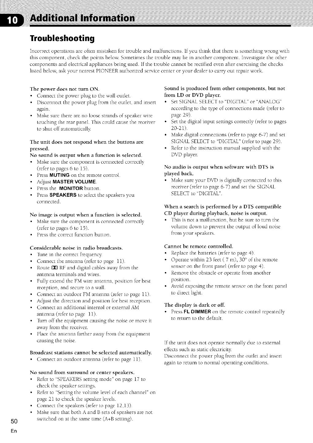
Troubleshooting
Incorrect operations are often mistaken tot trouble and malfunctions If you think that there is something wrong with
this component, check the points below¸ Sometimes the trouble may lie in another component¸ Investigate the other
components and electrical appliances being used¸ If the trouble cannot be rectified even after exercising the checks
listed beIo_ ask your nearest PIONEER authorized se_ice center or your dealer to carry out repair work¸
5O
En
The power does not turn ON.
Connect the power plug to the wail outlet
•Disconnect tile power plug {tom the outlet, and insert
again
•Make sure there are no loose strands of speaker wire
touching tile real: panel This could cause the receiver
to shut off automaticaI1),
The unit does not respond when the buttons are
pressed.
No sound is output when a fimction is selected.
•Make sure the component is ccmnected correctly
(refer to pages 6 to 15)
• Press MUTING on the remote control
• Adiust MASTER VOkUME
•Press the MONITOR button
• Press SPEAKERS to select the speakers),ou
connected
No image is output when a function is selected,
• Make sure the component is connected correctly
(refer to pages 6 to 15)
• Press the correct [unction button
Considerable noise in radio broadcasts,
• Tune in the correct {rcquenc_
Connect the antenna (refer to page 11)
• Route rlrl RF and digital cables away fl:om the
antenna terminals and wires
• Fully extend the FM wire antenna, position for best
reception, and secure to a wail
Connect an outdoor FM antenna (refer to page 11)
• Adiust the direction and position lot best reception
Connect an additional internal or external AM
antenna (refer to page 11)
• 7bin off the equipment causing the noise or move it
away flom the receiver
• Place the antenna farther away [tom the equipment
causing the noise
Broadcast stations cannot be selected automatically:
Connect an outdoor antenna (refer to page 11)
No sound from surround or center speakers.
• Refer to "SPE4.KERS setting mode" on page 17 to
check the speaker settings
• Refer to ' Setdng the volume level of each cbamlel" on
page 21 to check the speaker levels
Connect the speakers (refer to page 12,13)
• Make sure that both A and B sets of speakers are not
switched on at the same time (A+B setting)
Sound is produced from other components, but not
from LD or DVD player.
• Set SIGNAL SELECT to 'DIGITAL" or "ANALOG"
according to the type of connections made (refer to
page 29)
• Set the digital input settings correctly (reIer to pages
20 21)
• Make digital connections (refer to page 5 7) and set
SIGNAL SELECT to 'DIGITAL" (refer to page 29)
• Refer to the instruction manual supplied with the
DVD player
No audio is output when software with DTS is
played back.
• Make sure your DVD is digitally ccmnected to this
receiver (refer to page 6 7) and set the SIGNAL
SELECT to 'DIGITAL"
When a search is perIbrmed by a DTS compatible
CD player during playback, noise is output.
•Tbis is not a malfunction, but be sure to turn the
volume down to prevent the output of loud noise
[rom your speakers
Cannot be remote controlled,
•Replace the batteries (refer to page 4)
• Operate within 23 feet ( 7 m), 30° of the remote
sensor on the h:ont panel (refer to page 4)
•Remove the obstacle or operate flom another
position
•Avoid exposing the remote sensor on the front panel
to direct ligbt
The display is dark or of[,.
•Press FL DIMMER on the remote control repeatedly
to return to the default
If the unit does not operate normally due to external
effects such as static electrici b
Disconnect the power plug [tom the outlet and insert
again to return to normal operating conditions
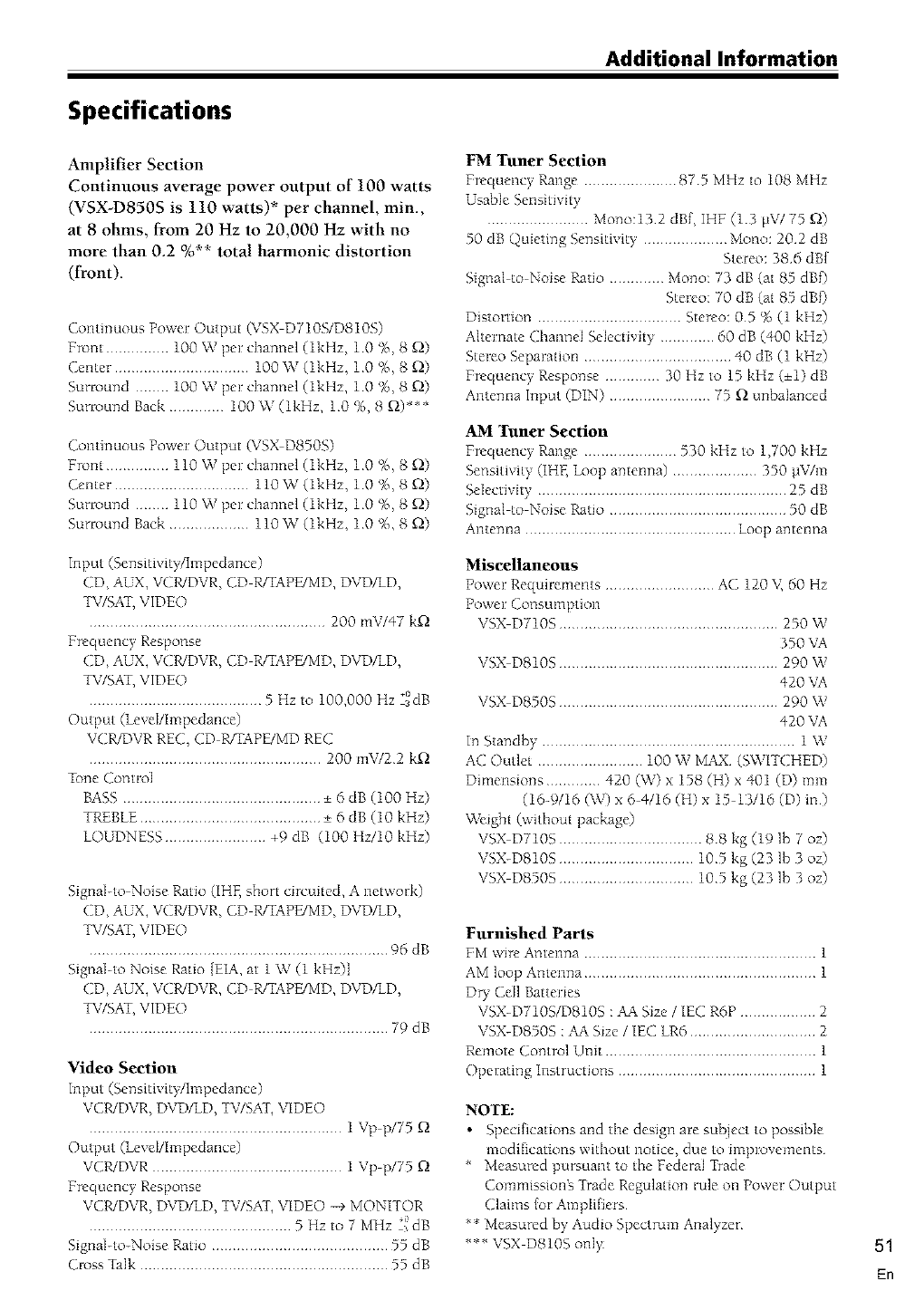
Additional Information
Specifications
Amplifier Section
Continuous average power output of 100 watts
(VSX-D850S is 110 watts)* per channel, min.,
at 8 ohms, from 20 Hz to 20,000 Hz with no
more than 02 %** total harmonic distortion
(front).
Continuous Power Output (VSX D710S/D810S)
Front ............... 100 W per channel (lkHz, 10 %, 8 Q)
Center ................................ 100 W (lkHz, 10 %, 8 [2)
Surround ........ 100 W per chamlel (lkHz, 10 %, 8 [2)
Surround Back ............. 100 W (lkHz, 10 %, 8 f_)***
Continuous Power Output (VSX D850S)
Front ............... 110 W per channel (lkHz, 10 %, 8 Q)
Center ................................ 110 W (lkHz, 10 %, 8 Q)
Surround ........ 110 W per channel (lkHz, 10 %, 8 [2)
Sunound Back ................... 110 W (lkHz, 10 %, 8 Q)
Input (Sensitivity/Impedance)
CD, AUX, VCR/DVR, CD R/TAPE/MD, DVD/LD,
TV/SAT,VIDEO
........................................................ 200 mV/47 k_
Frequency Response
CD, AUX, VCWDVR, CD R/TAPE/MD, DVD/LD,
TV/SAT,VIDEO
......................................... 5 Hz to 100,000 Hz "a°dB
Output (lcveI/Impedance)
VCR/DVR RE(;, CD R/TAPE/MD REC
....................................................... 200 roW22 k_
_bne Control
BASS ............................................... + 6 dB (100 Hz)
TREBLE........................................... + 6 dB (10 kHz)
LOUDNESS ........................ +9 dB 100 Hz/10 kHz)
Signal-to Noise Ratio (IHF, short circuited, A network)
CD, AUX, VCR/DVR, CD R/TAPE/MD, DVD/LD,
TV/SAT,VIDEO
....................................................................... 96 dB
Signal-to Noise Ratio [EIA, at 1W (1 kHz)]
CD, AUX, VCR/DVR, CD R/TAPE/MD, DVD/LD,
TV/SAT,VIDEO
....................................................................... 79dB
Video Section
Input (Sensitivity/I mpeda nce)
VCR/DVR, DVD/LD, TV/SAT, VIDEO
............................................................ 1 Vp p/75
Output (lcveI/Impedance)
VCWDVR ............................................. 1 Vp p/75
Frequency Response
VCWDVR, DVD/LD, TV/SAT, VIDEO -+ MONITOR
................................................ 5 Hz to 7 MHz "'idB
Signal-to-Noise Ratio .......................................... 55 dB
(;l>ss Talk ........................................................... 55 dB
FM Tuner Section
Frequency Range ...................... 875 MHz to 108 MHz
Usable Sensitivity
........................ Mono:13 2 dBf, IHF (13 gV/75 Q)
50 dB Quieting Sensitivity .................... Mono: 202 dB
Stereo: 386 dBf
Signal to Noise Ratio ............. Mono: 73 dB (at 85 dBf)
Stereo: 70 dB (at 85 dBf)
Distortion .................................. Stereo: 05 %(1 kHz)
Alternate Channel Selectivity ............. 60 dB (400 kHz)
Stereo Separation ................................... 40 dB (1 kHz)
Frequency Response ............. 30 Hz to 15 kHz (+1) dB
Antenna Input (DIN) ........................ 75 _ unbalanced
AM Tuner Section
Frequency Range ...................... 530 kHz to 1,700 kHz
Sensitivity (IHF, Loop antenna) .................... 350 laV/m
Selectivity ........................................................... 25 dB
Signal to Noise Ratio .......................................... 50 dB
Antenna .................................................. Loop at?tenna
Miscellaneous
Power Requirements .......................... AC 120 V, 60 Hz
Power Consumption
VSX D710S .................................................... 250 W
350 VA
VSX D810S .................................................... 290 W
420 VA
VSX D8505 .................................................... 290 W
420 VA
It? Standby ............................................................ 1 W
AC Outlet ......................... 100 W MAX (SWITCHED)
Dimensions ............. 420 (%0 x 158 (H) x 401 (D) mm
(16-9/16 (W) x 6 4/16 (H) x 15 13116 (D) in)
_Veight (without package)
VSX D710S .................................. 88 kg (19 lb 7 oz)
VSX-D810S ................................ 105 kg (23 lb 3 oz)
VSX D850S ................................ 105 kg (23 lb 3 oz)
Furnished Parts
FM wire Antenna ....................................................... 1
AM loop Antenna ....................................................... 1
DW Ceil Batteries
VSX-D710S/D810S : AA Size /IEC R6P .................. 2
VSX-D850S : ,CA Size /IEC LR6 .............................. 2
Remote Control Unit .................................................. 1
Operating Instructions ............................................... 1
NOTE:
•Specifications and the design are subject to possible
modifications without notice, due to improvements
* Measured pursuant to the Federal Trade
Commissiong Trade Regulation rule on Power Output
Claims for Amplifiers
** Measured by Audio Spectrum Analyzer
*** VSX DS10S only 51
En
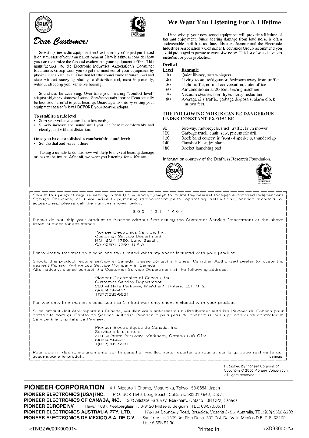
@
Selecting fine audio equipment such as flue unit you've just pmchased
is only Ihe start of yore ¸nmsical enjoyment. N ow it's time to consider how
you can maxhnize the lull told excitem6nt yore ¸ eqlupment oflers This
ir_anulucturer and the glectr_)nic ]llduslries Association's Cort£uln6r
Electronics Group want you u) get the most out of yore ¸ eqlupment by
playing it at a sale level. One that lets the sound conle Ibrough loud and
clear without annoying blaring or distortion and, most hnportantly,
without aflecting yore ¸ sensitive hearing.
Sound can be deceiving. Ovel time yore" hearing 'comfbrt level"
adapts to higher volumesof sound So what sounds ;_normaP'can actually
be luud and harnl_l to your Ilearing Guard against this by setting your
equipment at a sale level BEFORE yore" hearing adapts.
To establish a sati' level:
• Sta1_ yore volume contlol at a low setlulg
• Slowly incl_ase the sound until you can hear it com_rtably and
clearly, mid without distortion.
Once you have established a comtbr tabte sound level:
• Set the dial and leave it there
Taking aminule to do this now will help to prevent hearlug damage
or loss in the _mre After all, we want you listening let a lifelune
We Want You Listening For A Lifetime
Used wisely, your new sound equipment will provide a lifetime of
fun and enjoyment. Since hearing damage flora loud noise is often
undetectable until it is too lule, this maimfacturer and the Electronic
hldustries Assoclutioi_'s Consumer Elecu'onics Group recommend you
avoid prolonged exposul'e to excessive I_oise This list of sound levels is
included for your pl'otecdon.
Decibel
30 Quiet library, soft whispers
40 Living room, relYigerator, bedroom away Itom traffic
50 Light traI/3c, normal conversation, quiet office
66 Air conditioner at 2B feet, sewing machine
70 Vacuum cleaner, hair dryer, noisy restaurant
80 Average city traffic, garbage disposals, alarm clock
at two feet.
THE FOLLOWING NOISES CAN BE DANGEROUS
UNDER CONSTANT EXPOSURE
9B
106
126
14B
180
Subway, motorcycle, truck traffic, lawn mower
Garbage b'uck, chain saw, pneumatic drill
Rock band concert in fronl of speakers, thunderclap
Gunshot blast, jet plane
Rocket launching pad
Int_)rrllagon courtesy of the Deafnes_ Research Foundation.
@
_I
Should Lhls product f_,quire service it/ tile U S A and you wish to locates the nearest Plun@@r Authoriz_d [r/d_spender/t
Service Cof_/pal_y, or if you wish to purchase replao@mel_t pa_ts, op@ratlng instructiol_s, servtc@ rY_al_ua]s, or
accessories, pleas@ call the nur_/b@f shown below
800 42/ /404
Please do not ship your product to Pioneer without first calling the CustorT/@r S@fvlcez Department at the above
listed number for ass_stal_C@
£qor/eer Electronics Sefvlct% [rl(
Customer Service Departl /_r/t
RO BOX /760, Long Beach,
CA 90801 I760, u S A
For warranty luformation please See the Lil /ited Warranty sheet Jr/eluded with your product
Should this product requlre service it/ Canada, please 00r/tact a Pioneer Car/adlarl Authorized Dealer to locate', the
i_e_rest Ploneer Authorized Service Cor_lpany in Canad_
Alterr/atively, please contact the Customer Selvice Department at the following address;
Pioneer Electlonics of Garlada, Ir/c
(';ustorT/er Service Depart/T/ellt
300 Allstate Parkway, Markham, O_ltar_o L3R OP2
(9051479 44 I 1
/ 18771283 590/
For warranty information please see the Lil /ited Warranty sheet irlcluded with your product
ISi ce produd dolt @tre r6,,pard_ au Canada, veuillez vous adresser & un distllbuteur autoris_ Pioneer du Canada pour I
obtenir lu nora du C@ntr_ d@ Service,, autons@ P_on@@r le plus pr@s de,, chez vous Vous pouvez aussl contacter le I
Service a la cllunt&lu de P_or/eer:
Pioneer lectloniques du Canada, [r/c
Selvice & la cller/t_le
300, Allstate Parkway, Markham, Ontario L3R OP2
(9051479-44 I 1
/ 18771283 590/
Pour obtt_nir des rt,r/selgrlements sur [a garanti(_, veui[lez vous reporter au feuillet sur la garantle restrelr/te qu_
aCCOl_pagr/@ le produit _Ole_ZL
-I
Published by Pioneer Corporation¸
Copyright © 2000 Pioneer C0rp0ratl0n
All rigi/ts reselved
PIONEER CORPORATION 4 1. Megur0 1 Ch0me. Megur0 ku. Tokyo 153-8654. Japan
PIONEER ELECTRONICS [USA] INC. PQ BOX 1540. Long Beach, Calilomia 90801 1540. USA
PIONEER ELECTRONICS OF CANADA, INC. 300 Allstate Parkway. Markham. Ontario L3R OP2. Canada
PIONEER EUROPE NV Haven 1087, Keetberglaan 1, B 9120 Mebeb, Belgium TEL: 03/5700511
PIONEER ELECTRONICS AUSTRALIA PTY. LTD. 178-184 Boundary Roadr Braesider V ctoria 3195. Australiar TEL: [0319586 6300
PIONEER ELECTRONICS DE MEXICO S.A. DE C.V. San Lorenzo 1009 3er Piso Desp 302 C01 Del Valle Mexico DF CP 03100
TEL: 5 688 52 90
<TN GZW/00K00001> Printed in <XRB3004-A>
