Pismolabs Technology P193067 Peplink, Pepwave, Pismo Labs Wireless Product User Manual
Pismo Labs Technology Limited Peplink, Pepwave, Pismo Labs Wireless Product
UserManual.wiki
>
Pismolabs Technology
>
P193067 User Manual
User manual
Navigation menu
Upload a User Manual
Namespaces
Wiki Guide
HTML
PDF
Info
Views
User Manual
Discussion / Help
Navigation

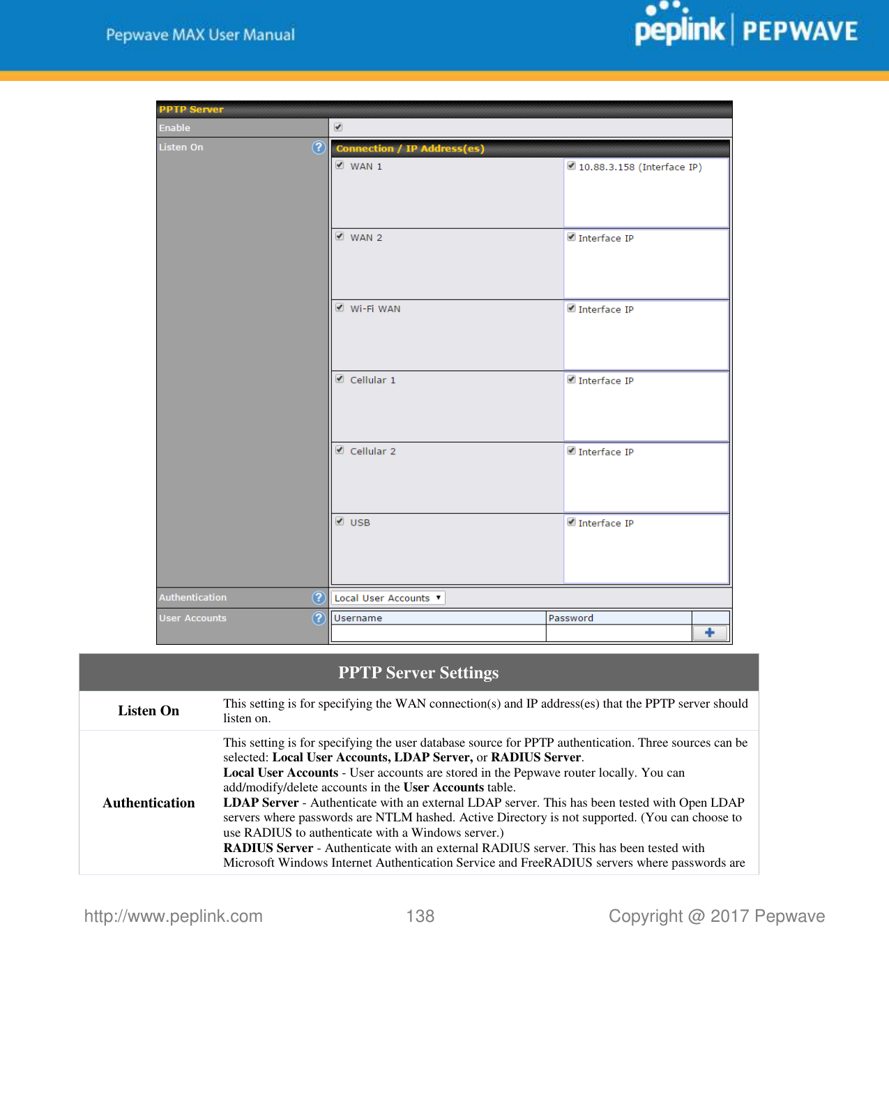
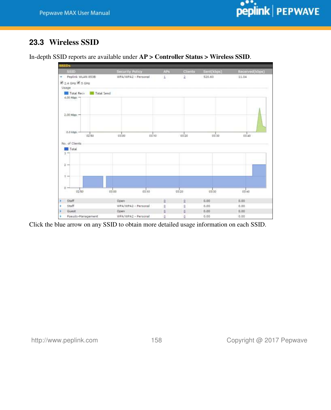

![http://www.peplink.com 203 Copyright @ 2017 Pepwave Česky [Czech] [Jméno výrobce] tímto prohlašuje, že tento [typ zařízení] je ve shodě se základními požadavky a dalšími příslušnými ustanoveními směrnice 1999/5/ES. Dansk [Danish] Undertegnede [fabrikantens navn] erklærer herved, at følgende udstyr [udstyrets typebetegnelse] overholder de væsentlige krav og øvrige relevante krav i direktiv 1999/5/EF. Deutsch [German] Hiermit erklärt [Name des Herstellers], dass sich das Gerät [Gerätetyp] in Übereinstimmung mit den grundlegenden Anforderungen und den übrigen einschlägigen Bestimmungen der Richtlinie 1999/5/EG befindet. Eesti [Estonian] Käesolevaga kinnitab [tootja nimi = name of manufacturer] seadme [seadme tüüp = type of equipment] vastavust direktiivi 1999/5/EÜ põhinõuetele ja nimetatud direktiivist tulenevatele teistele asjakohastele sätetele. English Hereby, [name of manufacturer], declares that this [type of equipment] is in compliance with the essential requirements and other relevant provisions of Directive 1999/5/EC. Español [Spanish] Por medio de la presente [nombre del fabricante] declara que el [clase de equipo] cumple con los requisitos esenciales y cualesquiera otras disposiciones aplicables o exigibles de la Directiva 1999/5/CE. Ελληνική [Greek] ΜΕ ΤΗΝ ΠΑΡΟΥΣΑ [name of manufacturer] ΔΗΛΩΝΕΙ ΟΤΙ [type of equipment] ΣΥΜΜΟΡΦΩΝΕΤΑΙ ΠΡΟΣ ΤΙΣ ΟΥΣΙΩΔΕΙΣ ΑΠΑΙΤΗΣΕΙΣ ΚΑΙ ΤΙΣ ΛΟΙΠΕΣ ΣΧΕΤΙΚΕΣ ΔΙΑΤΑΞΕΙΣ ΤΗΣ ΟΔΗΓΙΑΣ 1999/5/ΕΚ. Français [French] Par la présente [nom du fabricant] déclare que l'appareil [type d'appareil] est conforme aux exigences essentielles et aux autres dispositions pertinentes de la directive 1999/5/CE. Italiano [Italian] Con la presente [nome del costruttore] dichiara che questo [tipo di apparecchio] è conforme ai requisiti essenziali ed alle altre disposizioni pertinenti stabilite dalla direttiva 1999/5/CE. Latviski [Latvian] Ar šo [name of manufacturer / izgatavotāja nosaukums] deklarē, ka [type of equipment / iekārtas tips] atbilst Direktīvas 1999/5/EK būtiskajām prasībām un citiem ar to saistītajiem noteikumiem. Lietuvių [Lithuanian] Šiuo [manufacturer name] deklaruoja, kad šis [equipment type] atitinka esminius reikalavimus ir kitas 1999/5/EB Direktyvos nuostatas. Nederlands [Dutch] Hierbij verklaart [naam van de fabrikant] dat het toestel [type van toestel] in overeenstemming is met de essentiële eisen en de andere relevante bepalingen van richtlijn 1999/5/EG. Malti [Maltese] Hawnhekk, [isem tal-manifattur], jiddikjara li dan [il-mudel tal-prodott] jikkonforma mal-ħtiġijiet essenzjali u ma provvedimenti oħrajn relevanti li hemm fid-Dirrettiva 1999/5/EC. Magyar [Hungarian] Alulírott, [gyártó neve] nyilatkozom, hogy a [... típus]megfelel a vonatkozó alapvetõ követelményeknek és az 1999/5/EC irányelv egyéb elõírásainak. Polski [Polish] Niniejszym [nazwa producenta] oświadcza, że [nazwa wyrobu] jest zgodny z zasadniczymi wymogami oraz pozostałymi stosownymi postanowieniami Dyrektywy 1999/5/EC. Português [Portuguese] [Nome do fabricante] declara que este [tipo de equipamento] está conforme com os requisitos essenciais e outras disposições da Directiva 1999/5/CE. Slovensko [Slovenian] [Ime proizvajalca] izjavlja, da je ta [tip opreme] v skladu z bistvenimi zahtevami in ostalimi relevantnimi določili direktive 1999/5/ES. Slovensky [Slovak] [Meno výrobcu] týmto vyhlasuje, že [typ zariadenia]spĺňa základné požiadavky a všetky príslušné ustanovenia Smernice 1999/5/ES. Suomi [Finnish] [Valmistaja = manufacturer] vakuuttaa täten että [type of equipment = laitteen tyyppimerkintä] tyyppinen laite on direktiivin 1999/5/EY oleellisten vaatimusten ja sitä koskevien direktiivin muiden ehtojen mukainen. Svenska [Swedish] Härmed intygar [företag] att denna [utrustningstyp] står I överensstämmelse med de väsentliga egenskapskrav och övriga relevanta bestämmelser som framgår av direktiv 1999/5/EG.](https://usermanual.wiki/Pismolabs-Technology/P193067/User-Guide-3761905-Page-203.png)
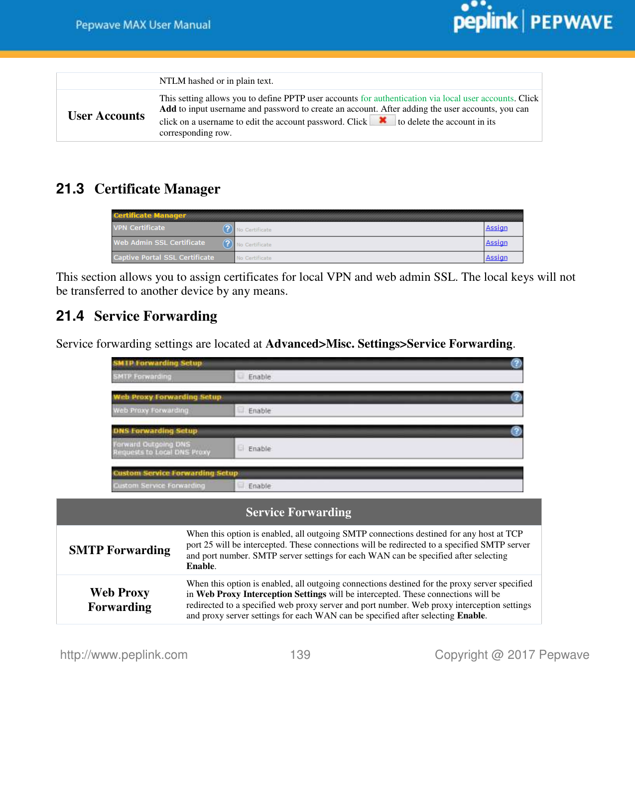
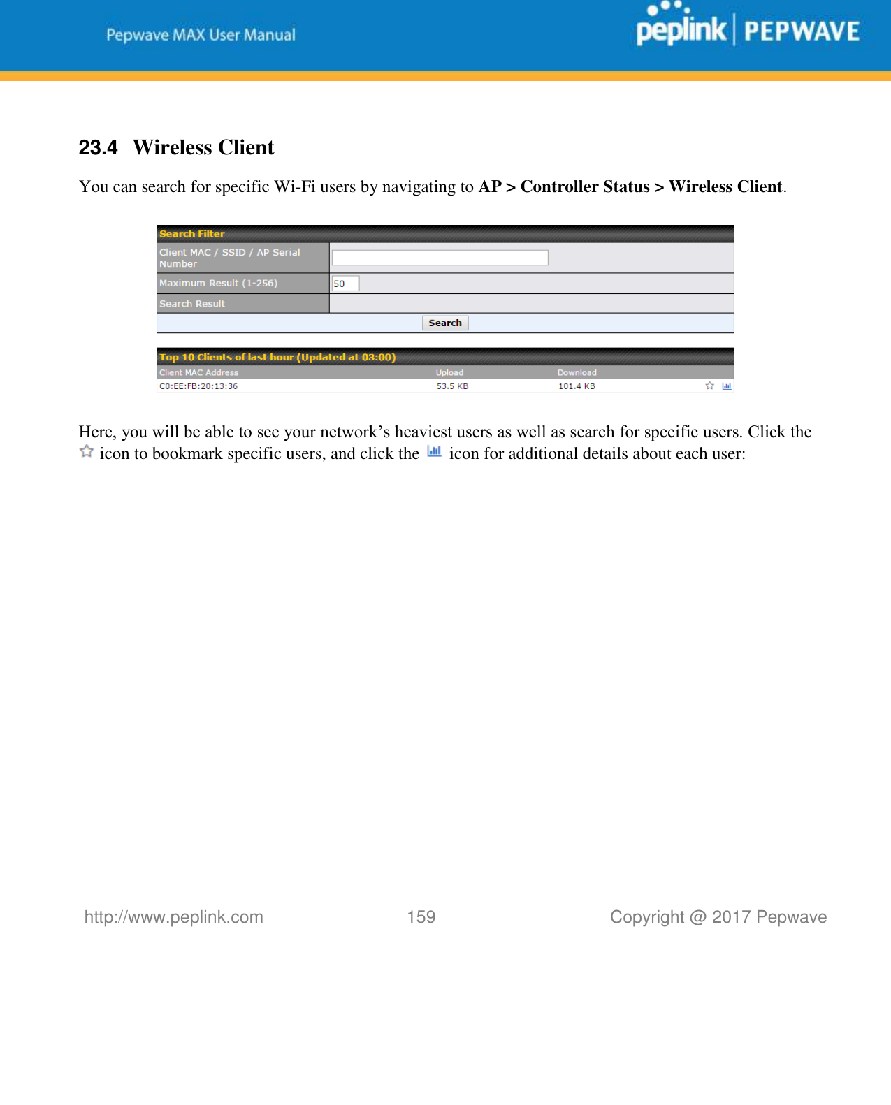
![http://www.peplink.com 204 Copyright @ 2017 Pepwave 4. NCC for Pepwave Routers For MAX Transit, MAX BR1 MK2, MAX BR1 MK2 LTE WLAN [警語] 「電磁波曝露量 MPE 標準值 1mW/cm2,本產品使用時建議應距離人體 24 cm」 電磁波 「減少電磁波影響,請妥適使用」。 [警語內容] (1) 電磁波警語標示:「減少電磁波影響,請妥適使用」。 標示方式:必須標示於設備本體適當位置及設備外包裝及使用說明書上。 低功率電波輻射性電機管理辦法 第十二條 經型式認證合格之低功率射頻電機,非經許可,公司、商號或使用者均不得擅自變更頻率、加大功率或變更原設計之特性及功能。 第十四條 低功率射頻電機之使用不得影響飛航安全及干擾合法通信;經發現有干擾現象時,應立即停用,並改善至無干擾時方得繼續使用。前項合法通信,指依電信法規定作業之無線電通信。低功率射頻電機須忍受合法通信或工業、科學及醫療用電波輻射性電機設備之干擾。 本行動寬頻設備的行動寬頻頻段(LTE900/LTE1800) 警告使用者: 此為甲類資訊技術設備,於居住環境中使用時,可能會造成射頻擾動,在此種情況下,使用者會被要求採取某些適當的對策。](https://usermanual.wiki/Pismolabs-Technology/P193067/User-Guide-3761905-Page-204.png)