PJNF Technologies 100-S WIRELESS RAIN SENSOR User Manual manual
PJNF Technologies, Inc. WIRELESS RAIN SENSOR manual
Users Manual
12
Disclaimer
This device does not provide automatic protection from hurricanes.
If your electric power fails, the automatic storm shutter control will
not function. Of course, your conventional electric storm shutter
controls will not function either. In the event of stormy weather,
when an electric power outage is likely, lower your storm shutters
just as you would with conventional storm shutter controls.
Liability
PJNF Technologies, Inc. assumes no liability for any damage to
original shutter drive equipment (motors, limit switches, slats, etc.)
resulting from use of the DryLanai
™
Automatic Storm Shutter
Control System. Changes or modifications not expressly approved
by PJNF Technologies, Inc. could void the user’s authority to
operate the equipment.
DryLanai
™
AUTOMATIC STORM SHUTTER CONTROL
OPERATING INSTRUCTIONS
Thank you for purchasing the DryLanai
™
Automatic Storm
Shutter Control. It will reliably protect your furniture, rugs and
other valuable possessions from rain damage and relieve you of the
need to mop up your porch or lanai floor after every rain shower.
Your safety and the safety of others are very important.
Important safety messages have been provided throughout this
manual and are repeated at the beginning of these instructions in
accordance with electrical safety regulations. Always read and
obey all safety messages.

2
This is the safety alert symbol.
This symbol alerts you to potential hazards that can kill or hurt you
and others.
All safety messages follow the safety alert symbol and the word
“WARNING.” This means:
WARNING
You can be killed or seriously injured if you don’t follow
instructions.
Safety messages will tell you what the potential hazard is and how
to reduce the chance of injury.
WARNING Electrical Shock Hazard
Disconnect electrical power at the circuit breaker box before
installing or servicing the DryLanai
™
Controller. Failure to do so
can result in death or electrical shock.
WARNING
This product must be connected to a grounded, metal, permanent
wiring system; or an equipment-grounding conductor must be run
with the circuit conductors and connected to the equipment-
grounding terminal or lead on the product.
11
• If the Controller detects a system fault (the signal light is
lit continuously), you may be unable to raise or lower your
shutters using the ZONE switches and the UP and DOWN
switches as described above. If this happens, your shutters
can be raised or lowered using the pushbutton switches
located on the bottom of the Controller enclosure (beneath
the ZONE
1 switch) until the fault is corrected. Use a non-
conductive pointed object, such as the tip of a ball-point
pen, to press these switches.
It may be possible to eliminate the fault indicated on the
Controller panel by disconnecting the electrical power at
the circuit breaker box for approximately ten seconds and
then reconnecting the power. The Controller will power up
again in the auto mode.
• If necessary, the Controller can be reset by following these
steps:
1. Touch the ZONE 1, ZONE 2 and MODE switches
simultaneously and continuously until both the auto
and manual lights blink.
2. The Rain Sensors must be “re-enrolled” following the
procedure outlined in the previous section of these
instructions.
10
back to the auto mode. Ordinarily, Rain Sensor grids will
dry out spontaneously within a few minutes, and manually
drying them is not required.
• Your shutters will not close automatically if rain is not
coming into your lanai. Rain drops must strike the grid on
the front surface of a Rain Sensor in order to trigger the
automatic closure of your shutters.
• Clean your Controller and Rain Sensors periodically using
a soft damp cloth. Remember to toggle the Controller to
the manual mode when cleaning the Rain Sensors to avoid
accidentally closing your shutters. Do not attempt to polish
the Rain Sensor grids with solvents or abrasive materials;
this will reduce the useful lifetime of the Rain Sensor.
• Each Rain Sensor supplied with your DryLanai
™
Automatic Storm Shutter Control System contains a
CR-123 Lithium battery that should function for many
months under ordinary conditions. The battery light on
the Controller panel will alert you when batteries need
replacement. When this happens, replace the batteries in
all of your Rain Sensors.
• To replace Rain Sensor Batteries, follow these steps:
1. Toggle the Controller to the manual mode.
2. Remove the screws on the bottom panel of the Rain
Sensor.
3. Remove the old battery and replace it with a fresh CR-
123 Lithium battery.
4. Replace the bottom panel and secure it with the screws
you removed in Step 1.
5. Repeat Steps 2 – 4 for all Rain Sensors.
6. Replace the Rain Sensors in their original locations
7. Toggle the Controller back to the auto mode.
3
WARNING
To reduce the risk of fire, electric shock or injury to persons,
installation work and electrical wiring must be done by a qualified
person or persons in accordance with all applicable codes and
standards. The controller is for indoor use only.
WARNING
This product has no user serviceable parts. Do not open the Wall
Controller enclosure or attempt to perform alterations or
maintenance on the Controller wiring. All servicing should be
performed by an authorized service representative.
WARNING
To reduce the risk of fire or electric shock, install this controller
only with tubular roll down shutter operator/motors rated
maximum 2.75A each.
WARNING
This appliance has been evaluated for fire and shock only, not
entrapment. The controller may be used only with louver and
shutter operators for which the application has been evaluated by
UL. The maximum weight of each shutter shall not exceed 350
pounds.

4
Important: Read and Save These Instructions.
They will:
• Make operation of your automatic storm shutters easier.
• Help you in the future if you have questions.
How Your Automatic Storm Shutter Control Works
The DryLanai
™
Automatic Storm Shutter Control System consists
of a Controller, which is mounted on a wall inside your home, and
one or more Rain Sensors, which sit on on your porch or lanai
floor.
You can raise and lower your storm shutters using the touch
controls on the front panel of the Controller, the same as if you
were using conventional switches.
When rain drops strike the grid on the front surface of any Rain
Sensor, the Rain Sensor sends a radio frequency (RF) signal to the
Controller, which automatically closes all the shutters. When rain
is over, the shutters can be raised again using the touch switches on
the front panel of the Controller.
The Rain Sensors are powered by long-life batteries. Each Rain
Sensor continuously monitors the voltage of its battery. When the
battery voltage falls below a predetermined level, the Rain Sensor
sends a special RF signal to the Controller that closes all the
shutters and lights a warning light on the front panel of the
Controller, advising you to replace the batteries. This assures that
your automatic shutter control will not fail because of dead
batteries.
9
• If the signal light on the Controller panel does not light
when a Rain Sensor pushbutton switch is pressed, the Rain
Sensor must be “enrolled” so the Rain Sensor and
Controller can communicate. This is achieved by bringing
the Rain Sensor into close proximity with the Controller
(4 feet or less) and performing the following steps:
• Touch ZONE 1 switch and ZONE 2 switches
simultaneously and continuously until all the ZONE lights
begin to flash. While the lights are flashing, momentarily
press the pushbutton switch on the rear side of the Rain
Sensor. The signal light will light momentarily and the
flashing ZONE lights will go out. Test to ensure the
process was successful by momentarily depressing the
pushbutton switch on the rear side of the Rain Sensor
again. The signal light on the panel will momentarily
light.
• Repeat this sequence for the other Rain Sensors.
Your automatic shutter control system is now fully operational.
Additional Important Information
• The Rain Sensor sends a signal to the Controller when it
senses that the grid on its front surface is changing from
dry to wet. Even though it takes only one rain drop on a
grid to initiate the signal, the grid must be completely dry
when rain first strikes it. Raising your shutters immediately
after a rain shower may cause the automatic system to
malfunction if another shower occurs before your Rain
Sensor grids have completely dried off. You can prevent
this from happening by toggling the Controller to the
manual mode, drying the Rain Sensor grids with a tissue,
paper towel or soft cloth, and then toggling the Controller
8
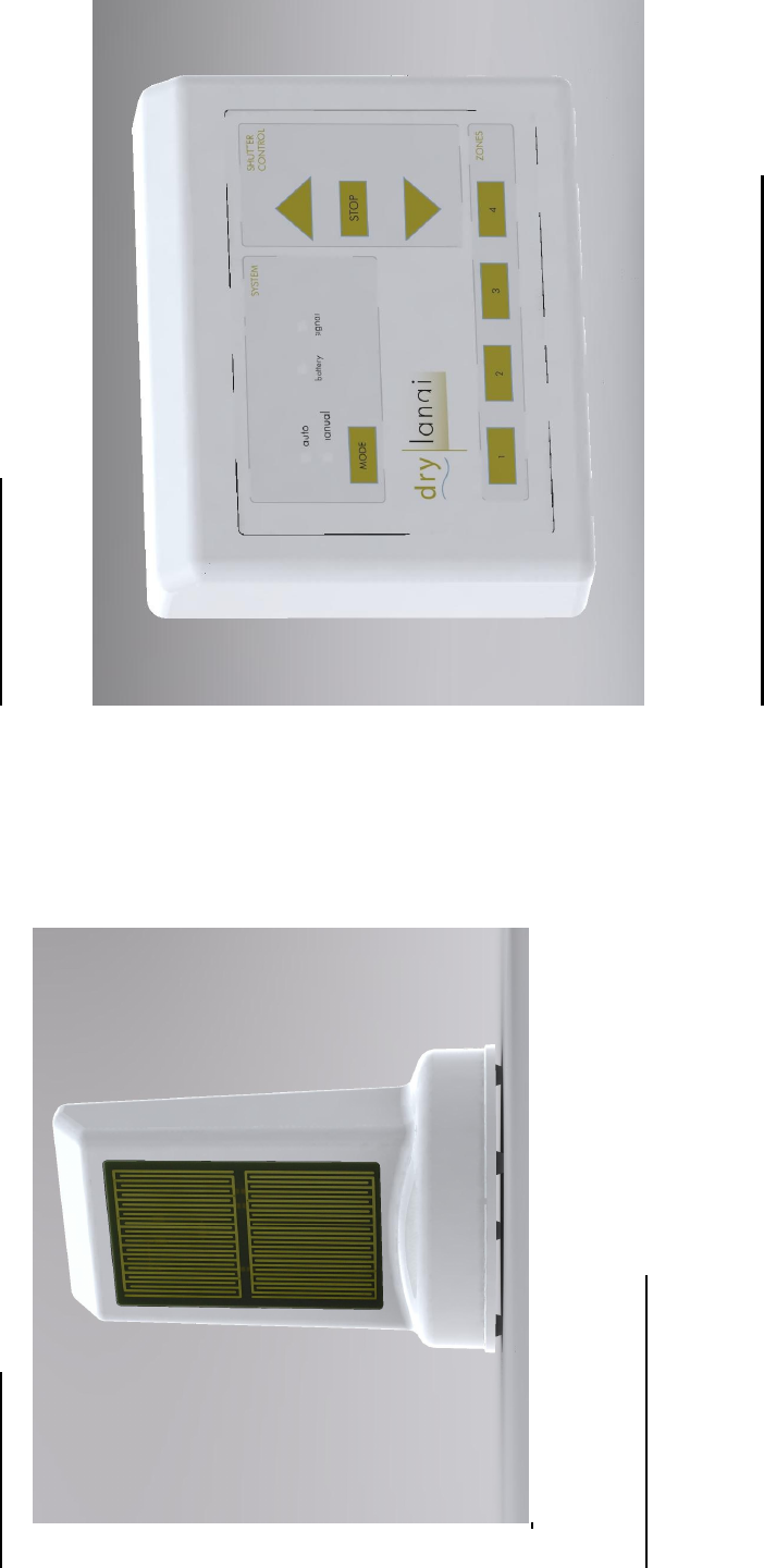
The Rain Sensors
Figure 2
Locating the Rain Sensors
One Rain Sensor is required for each screened exposure. For
example, if your lanai has screens facing East, South and West,
you need three Rain Sensors.
• Place a Rain Sensor on the floor within 12 inches of each
screened exposure with its detection grid facing the screen.
Check for viable RF links between the Rain Sensors and
the Controller by momentarily pressing the pushbutton
switch on the rear side of each Rain Sensor. The signal
light on the Controller panel will momentarily light when
each Rain Sensor switch is pressed.
5
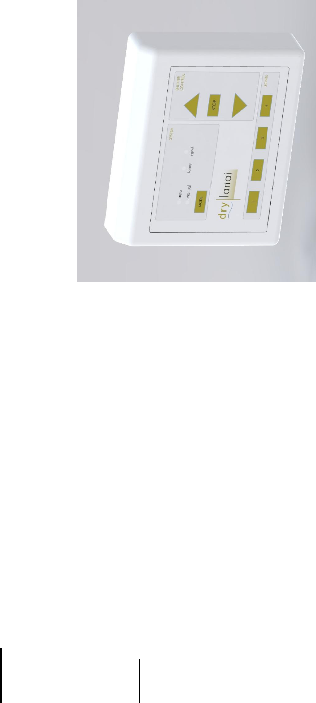
The Wall Controller
Figure 1
Description of the Wall Controller Touch Panel
The front Touch Panel of the Wall Controller provides means for
manually controlling your storm shutters and monitoring the state
of the DryLanai
™
Automatic Storm Shutter Control System.
• The MODE switch toggles the controller from manual
mode to auto (automatic) mode and back. In the auto
mode, the Controller is activated by RF signals from the
Rain Sensors. This is the normal operating mode of the
Shutter Control System. In the manual mode, the

6
Controller is not activated by signals from the Rain
Sensors. This enables you to clean the surfaces of the Rain
Sensors without activating the shutter controls and prevents
accidental closure of the shutters when you are using
liquids such as water, cleaning solutions and insecticides in
the vicinity of the Rain Sensors.
• The Controller reverts to the auto mode approximately
sixty minutes after having been toggled to the manual
mode. This helps to ensure that your shutters will be
controlled automatically if you forget to toggle the
Controller back to auto mode. The small lights above the
MODE switch indicate whether the Controller is in the
manual mode or the auto mode. Touch the MODE
switch and watch the mode lights change from auto to
manual. Touch the MODE switch again and watch the
mode lights change from manual back to auto. If the
electric power fails, the Wall Controller will start up again
in the auto mode.
• The light immediately to the right of the auto and manual
lights indicates the status of the Rain Sensor batteries. If
the battery in any Rain Sensor requires replacement, the
Controller will automatically close all the shutters and the
battery light will light continuously, alerting you to
replace the Rain Sensor batteries.
• The light immediately to the right of the battery light
indicates the status of the RF link between the Rain Sensors
and the Controller. Momentary lighting of this light
indicates that an RF signal is being received from a Rain
Sensor. If the system encounters a fault, such as RF
interference or malfunction of a component, the signal
light will light continuously, alerting you to seek technical
assistance.
7
• The touch switches labeled 1, 2, 3 and 4 near the bottom of
the panel enable you to raise or lower your storm shutters.
This works in both the auto mode and the manual mode.
Touching one or more of the ZONE switches lights the
light directly above the respective switch. While these
lights are lit, you can raise or lower the selected shutters by
touching the triangular UP switch or the triangular DOWN
switch. You cannot raise or lower a shutter if the light
above its corresponding switch is not lit. You can stop the
moving shutters at any time by touching the rectangular
STOP switch. The STOP switch overrides all manual
mode or auto mode operations.
WARNING Electrical Shock Hazard
Do not open the Controller enclosure to attempt to remedy a
system fault. Failure to observe this warning can result in
electrical shock or death. If your Controller requires repair or
replacement, call a qualified electrical service technician.

13
FCC Statements for the Wall Controller:
NOTE: This equipment has been tested and found to comply with
the limit for a Class B digital device, pursuant to part 15 of the
FCC Rules. These limits are designed to provide reasonable
protection against harmful interference in a residential installation.
This equipment generates, uses, and can radiate radio frequency
energy and, if not installed and used in accordance with the
instructions, may cause harmful interference to radio
communications. However, there is no guarantee that interference
will not occur in a particular installation. If this equipment does
cause harmful interference to radio or television reception, which
can be determined by turning the equipment off and on, the user is
encourage to try to correct the interference by one or the following
measures:
• Reorient or relocate the receiving antenna.
• Increase the separation between the equipment and receiver.
• Connect the equipment into an outlet on a circuit different from
that to which the receiver is connected.
• Consult the dealer or an experienced radio/TV technician for
help.
Changes or modifications not expressly approved by the
responsible party could void the user’s authority to operate the
equipment.

14
FCC Statements for the Rain Sensor:
Operation is subject to the following two conditions: (1) this
device may not cause interference, and (2) this device must accept
any interference, including interference that may cause undesired
operation of the device.
This device may only be used with the approved antennas that are
shipped with the unit and installed by the manufacturer. The use
of any other antennas will invalidate the unit’s FCC Part 15
certification.
To reduce potential radio interference to other users, the antenna
type and its gain should be so chosen that the equivalent
isotropically radiated power (e.i.r.p.) is not more than that
permitted for successful communication. Operating the device
with the supplied, internal antennas will ensure that this
requirement is met.
Changes or modifications not expressly approved by the
responsible party could void the user’s authority to operate the
equipment.
Manufactured by:
PJNF Technologies, Inc.
805 Bentwater Circle #104
Naples, FL 34108
(239) 594-2603