POINTER TELOCATION RMU17UHF-NXUS User Manual
POINTER TELOCATION Ltd.
UserManual.wiki
>
POINTER TELOCATION
>
RMU17UHF-NXUS User Manual
>
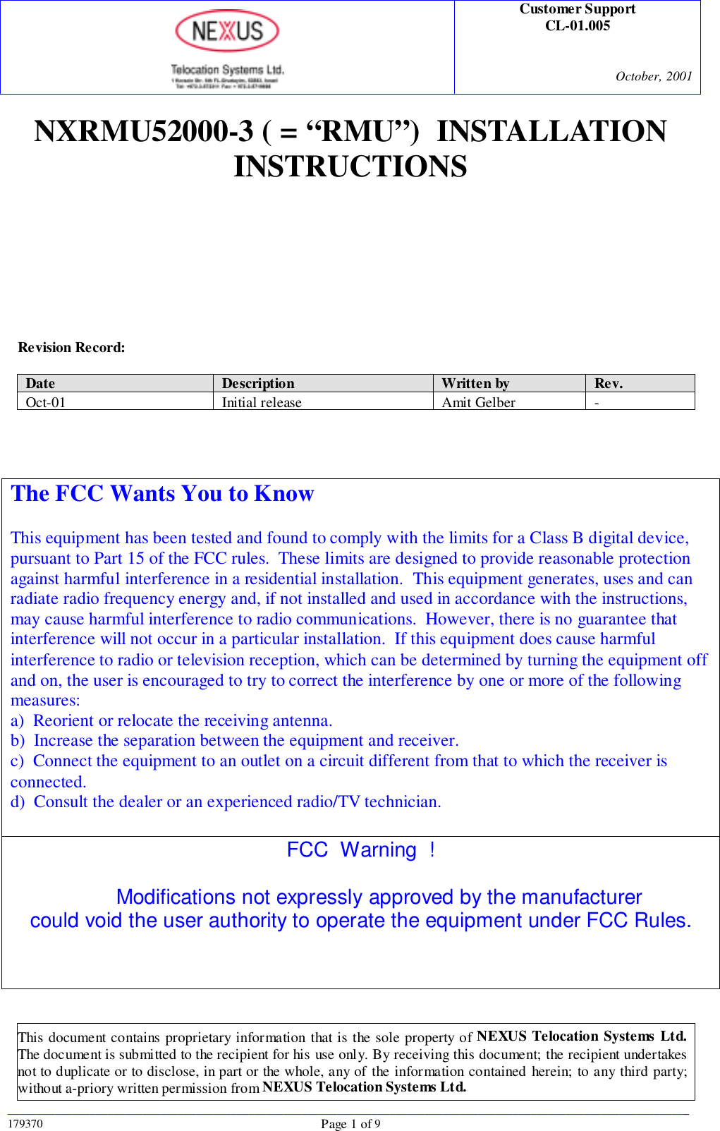
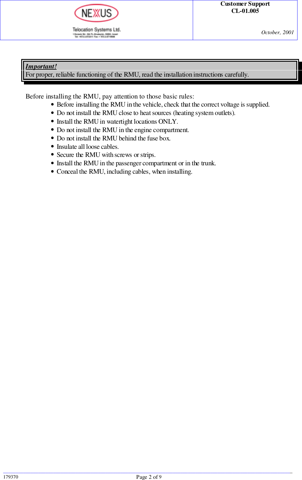
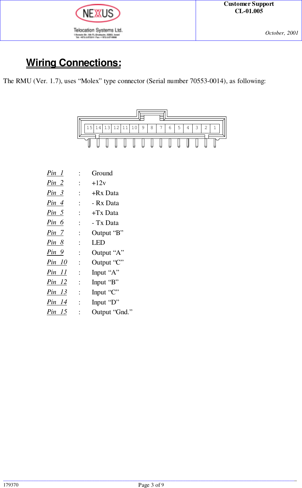
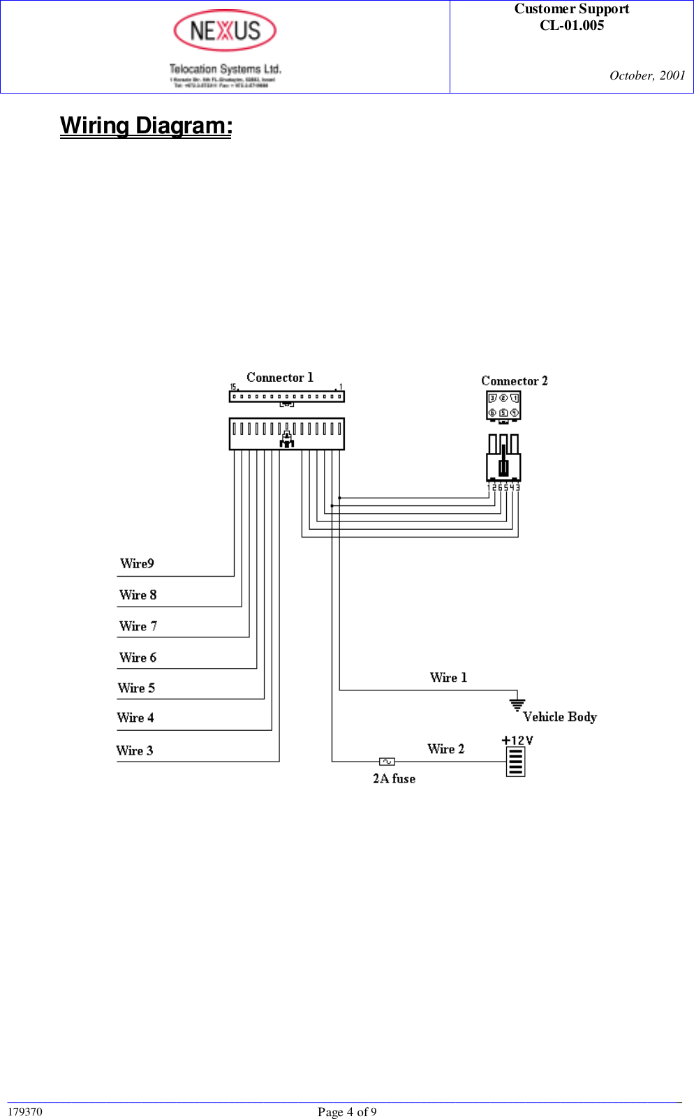
User Manual
Contents
1.
User Manual
2.
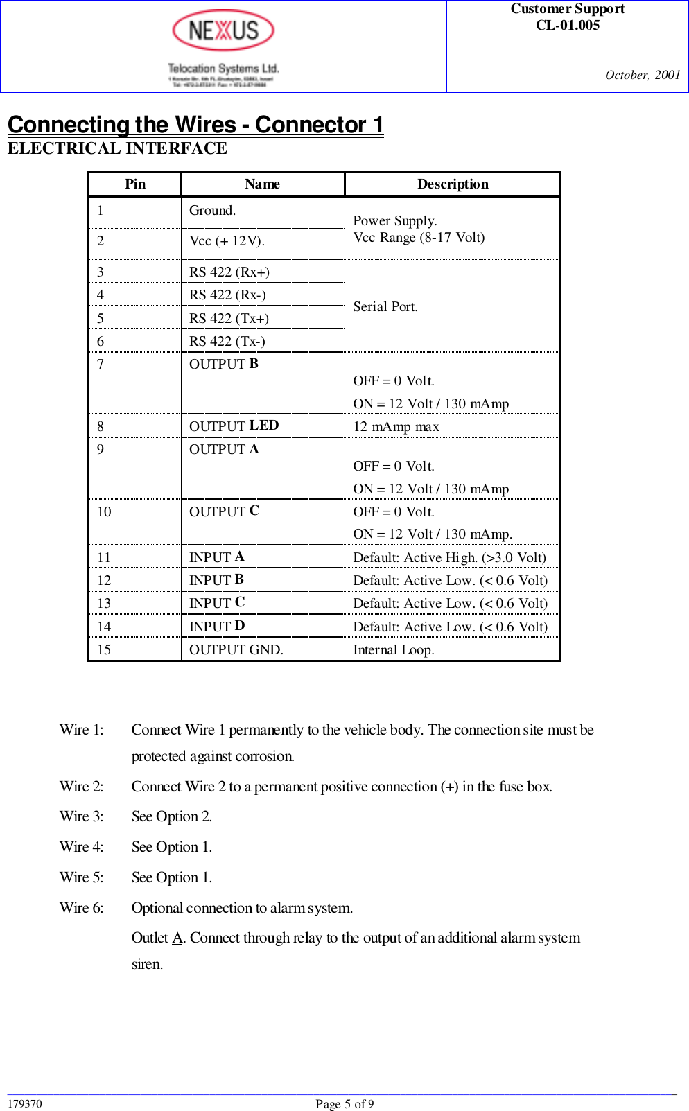
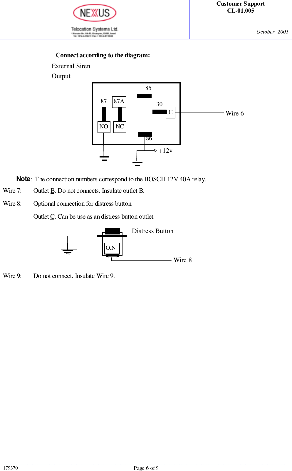
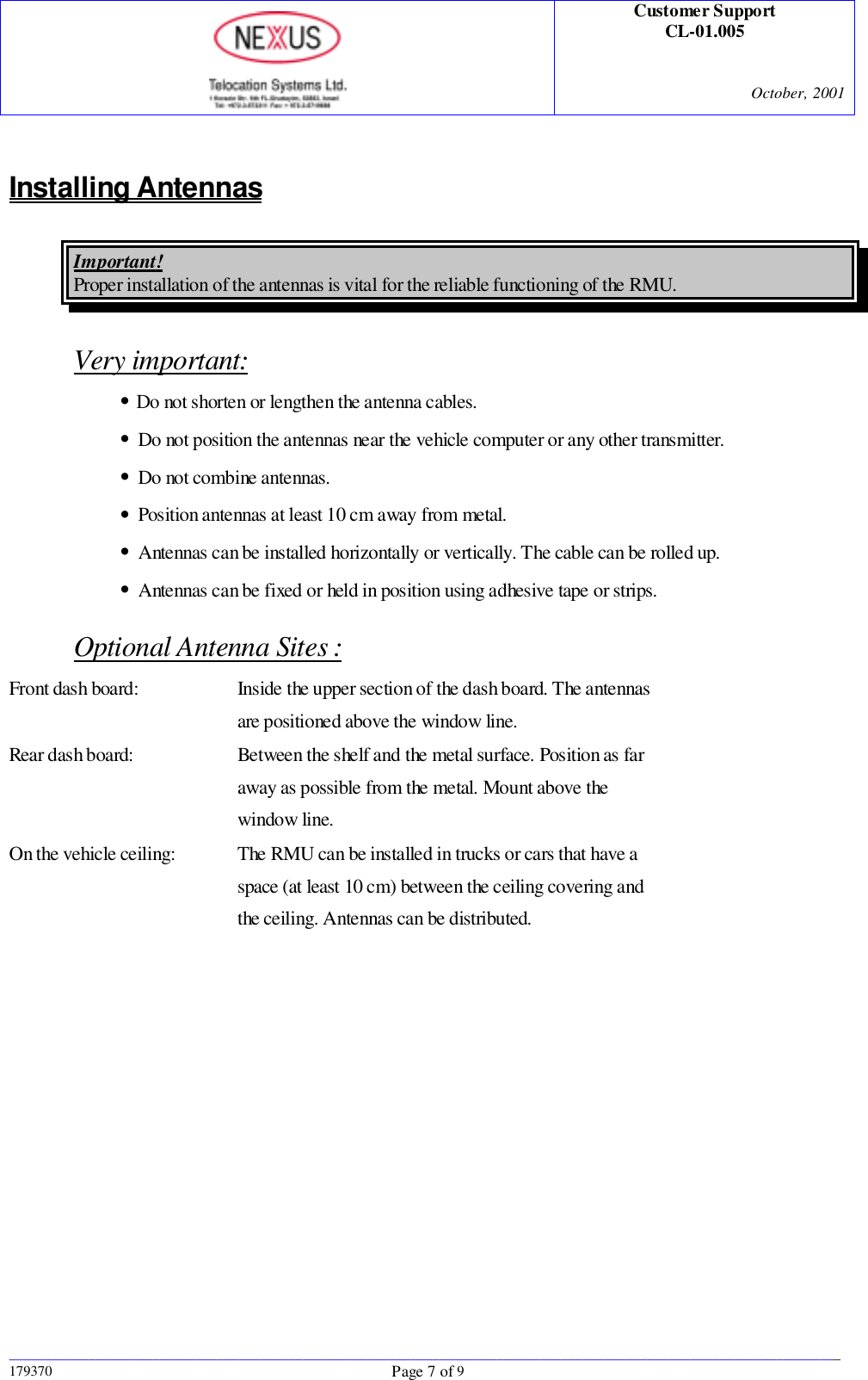
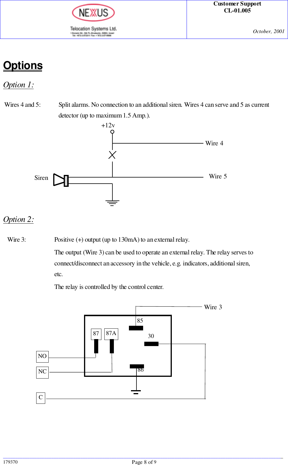
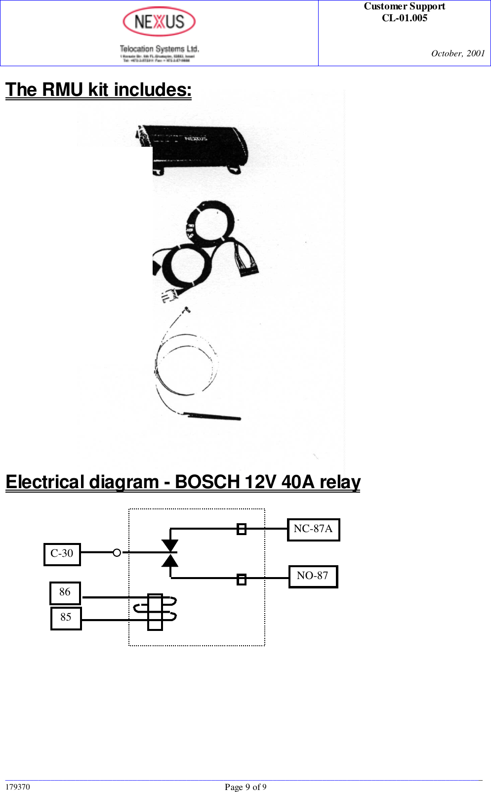
Revised Installation Manual
User Manual
Navigation menu
Upload a User Manual
Namespaces
Wiki Guide
HTML
PDF
Info
Views
User Manual
Discussion / Help
Navigation