PORTMAN ELECTRONICS GST-8000 GST8000 GPRS / GPS TRACKING SYSTEM User Manual gst8000 v2 0 1
PORTMAN ELECTRONICS (DONGGUAN) CO., LTD. GST8000 GPRS / GPS TRACKING SYSTEM gst8000 v2 0 1
UserManual.wiki
>
PORTMAN ELECTRONICS
>
GST 8000 User Manual
manual
Navigation menu
Upload a User Manual
Namespaces
Wiki Guide
HTML
PDF
Info
Views
User Manual
Discussion / Help
Navigation
![8C. MAIN INTERFACE 1. [User detail:] If the SIM card is password protected, user can input the “SIM PIN” window to set password of SIM Card. Set UNIT ID and UNIT password of for the device. Note: Device ID length does not more than 4-characters, otherwise SBD compressed packet will more than 30 bytes, and communication data fee is double.](https://usermanual.wiki/PORTMAN-ELECTRONICS/GST-8000/User-Guide-1228148-Page-9.png)
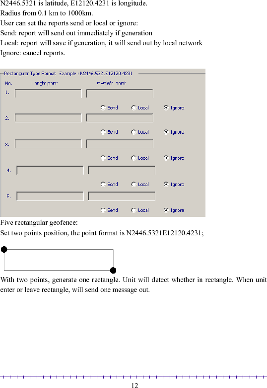
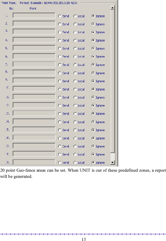
![11in order to make the connection. If the report sending using GPRS connection fails, the report will be sent to the ‘primary’ SMS number first. The report will be resent, when the GPRS connection becomes available. 2. [Geofence:] Four Circular Geofence and one self-geofence: Circular Geofence must set origin and radius: Origin format :N2446.5321E12120.4231;](https://usermanual.wiki/PORTMAN-ELECTRONICS/GST-8000/User-Guide-1228148-Page-12.png)
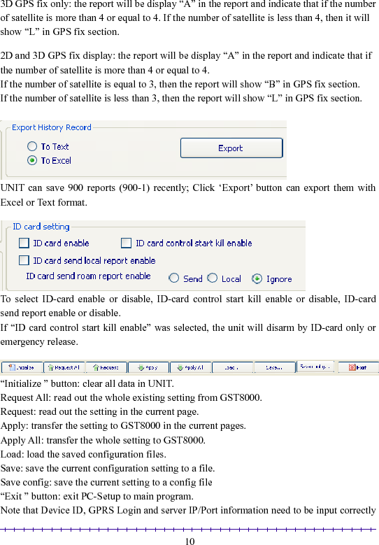
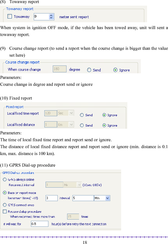
![143. [Report:] Automatic report can be configured in this section. To activate the function(s), please select “√” in checkbox and fill in data in the textbox. The reports will be summarized as (1) Local Intelligent report](https://usermanual.wiki/PORTMAN-ELECTRONICS/GST-8000/User-Guide-1228148-Page-15.png)
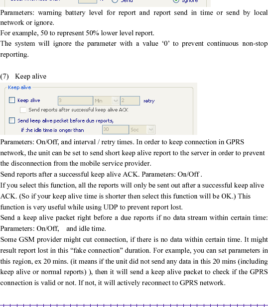
![15Parameters: report time when moving, report time when stop, threshold speed, send stop report after a preset value and to choose the reports send or ignore. Report when speed less than a preset value (refer the following 1.5 Km/Hr), and it will send stop report after the preset time (refer the following 120Sec). (min. speed is 0.1 km/Hr, max. speed is 1000 km/Hr). (2) Local Intelligent history report (record the report in the system’s flash ram) Parameters: Report time when moving, Report time when stop, and threshold speed. (min. speed is 0.1 km/Hr, max. speed is 1000 km/Hr). and to choose the reports send or ignore. (3) A/D 1 detect report [on/off] SEND REPORT IF ADC1 LESS THAN [min voltage] V for [debounce time] SEC, RESEND PER [resend time] SEC [on/off] SEND REPORT IF ADC1 MORE THAN [max voltage] V for [debounce time] SEC, RESEND PER [resend time] SEC [on/off] SEND REPORT IF ADC1 GO UP [up voltage] V for [debounce time] SEC [on/off] SEND REPORT IF ADC1 GO DOWN [down voltage] V for [debounce time] SEC [on/off] SEND REPORT IF ADC1 ENTER/EXIT [min voltage] V TO [max voltage] V for [debounce time] SEC Note: AD1 input voltage range is 0~3.30v, it must connect a resistance to share the voltage if the detected voltage higher than 3.30v.](https://usermanual.wiki/PORTMAN-ELECTRONICS/GST-8000/User-Guide-1228148-Page-16.png)
![16(4) A/D 2 detect report [on/off] SEND REPORT IF ADC2 LESS THAN [min voltage] V for [debounce time] SEC, RESEND PER [resend time] SEC [on/off] SEND REPORT IF ADC2 MORE THAN [max voltage] V for [debounce time] SEC, RESEND PER [resend time] SEC [on/off] SEND REPORT IF ADC2 GO UP [up voltage] V for [debounce time] SEC [on/off] SEND REPORT IF ADC2 GO DOWN [down voltage] V for [debounce time] SEC [on/off] SEND REPORT IF ADC2 ENTER/EXIT [min voltage] V TO [max voltage] V for [debounce time] SEC Note: AD2 input voltage range is 0~3.30v, it must connect a resistance to share the voltage if the detected voltage higher than 3.30v. (5) Speeding report Parameters: resend interval, threshold speed, over speed delay time, exit over speed delay time, alert when over speed and report send or ignore For example, if resend interval is 20 sec, enter over speed delay time is 20 sec, threshold](https://usermanual.wiki/PORTMAN-ELECTRONICS/GST-8000/User-Guide-1228148-Page-17.png)
![191) GPRS always on-line Parameters: Reconnect interval While using this mode, when the unit can not searched GPRS signal, system will reconnect GPRS interval a preset value. (e.g.: 1minute) 2) Base on report mode Parameters: Max. reconnect times, reconnect interval While using this mode, the unit will connect to the server when there is a report to send. If the first connection is failed, it will retry to connect to the server up to the max. reconnect times. Each retry will be separated by the reconnect “interval”. 3) GPRS connect once While using this mode, the unit will connect to the server when there is a report to send (but only try once). If it is not successful, the report will be stored and sent out in the next successful connection. Disconnect GPRS connection when report sending is completed. 4) Reduce GPRS dialup method Parameters: On/Off, Max. reconnect times, connect delay If this method is used, the unit will reduce the GPRS dial-up connection when the dial-up is failed after number of times. User can define the delay time for the unit before try to reconnect to the server. If there is trigger report, the unit will connect to server immediately. Special command for SMS mode: If the GST8000 is not in the GPRS online status, user can send command &&Y02 or &&Y04 to ask unit to connect to server. This command can be sent from any device via SMS; &&Y02: When received this command, system will actively try to connect to server in next 600 seconds. &&Y04,[connection time],[report interval]: For example: &&Y04, 3600, 60 When received this command, system will connect to server in the next 3600 seconds, and send one report out every 60 seconds.](https://usermanual.wiki/PORTMAN-ELECTRONICS/GST-8000/User-Guide-1228148-Page-20.png)
![204. [Roam alarm] All the roam reports configured are same as Local report. Send: report will send out immediately if generation Local: report will save if generation, it will send out by local network Ignore: cancel reports.](https://usermanual.wiki/PORTMAN-ELECTRONICS/GST-8000/User-Guide-1228148-Page-21.png)
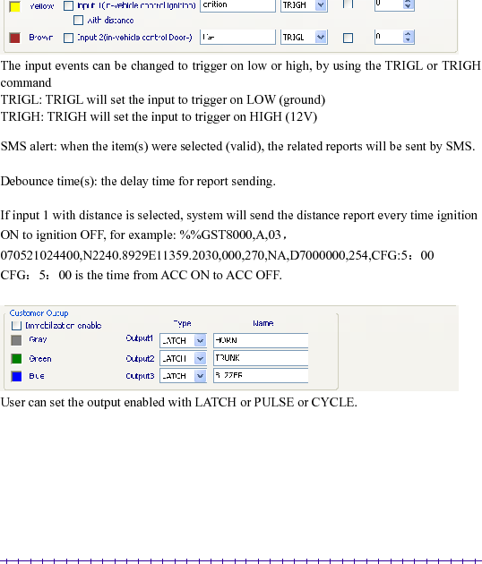
![215. [Alarm setup] Alarm report(s) is also configurable. User can customize the events generated by the in-vehicle input or build in car alarm to be sent to the server. If the item(s) be selected (VALID), the related reports will be sent. Otherwise the report will be ignored even when an event is occurred internally. Also build in car alarm function can be set on here. Sleep mode (when ignition OFF) (1) GST8000 can go to sleep mode when ignition goes off and TL-sensor not be trigger for 5minuts. In sleep mode, GPS will be disabled. All the auto report (Time, Distance, Intelligent…) will not be send when ignition goes off. (2) During the sleep mode, the system can wait up automatically and send a wake up diagnostic report. The automatic wakeup time is configurable. (Minimum duration is 5 minutes; maximum duration is 1000 Hours).](https://usermanual.wiki/PORTMAN-ELECTRONICS/GST-8000/User-Guide-1228148-Page-22.png)
![236. [Roam alarm] All the roam alarm configured are same as Local report. Send: report will send out immediately if generation Local: report will save if generation, it will send out by local network Ignore: cancel reports.](https://usermanual.wiki/PORTMAN-ELECTRONICS/GST-8000/User-Guide-1228148-Page-24.png)
![247. [GSM roaming] 1) Roaming GPRS mode](https://usermanual.wiki/PORTMAN-ELECTRONICS/GST-8000/User-Guide-1228148-Page-25.png)
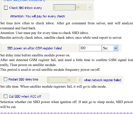
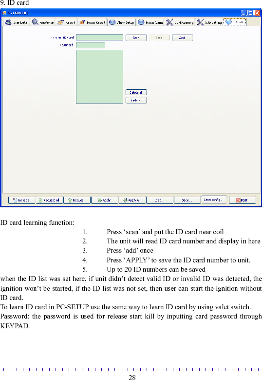
![26 8. [SBD setting] IMEI: Any operate with ‘request or request all’ after GPRS power on, the module series number will display automatically, otherwise it displayed with space. This report is special for satellite module. It is different to intelligent report defined in common report setting. This report only work when no GSM coverage. Attention: because consumption with satellite is different to GPRS/SMS. Pay attention to report frequency.](https://usermanual.wiki/PORTMAN-ELECTRONICS/GST-8000/User-Guide-1228148-Page-27.png)