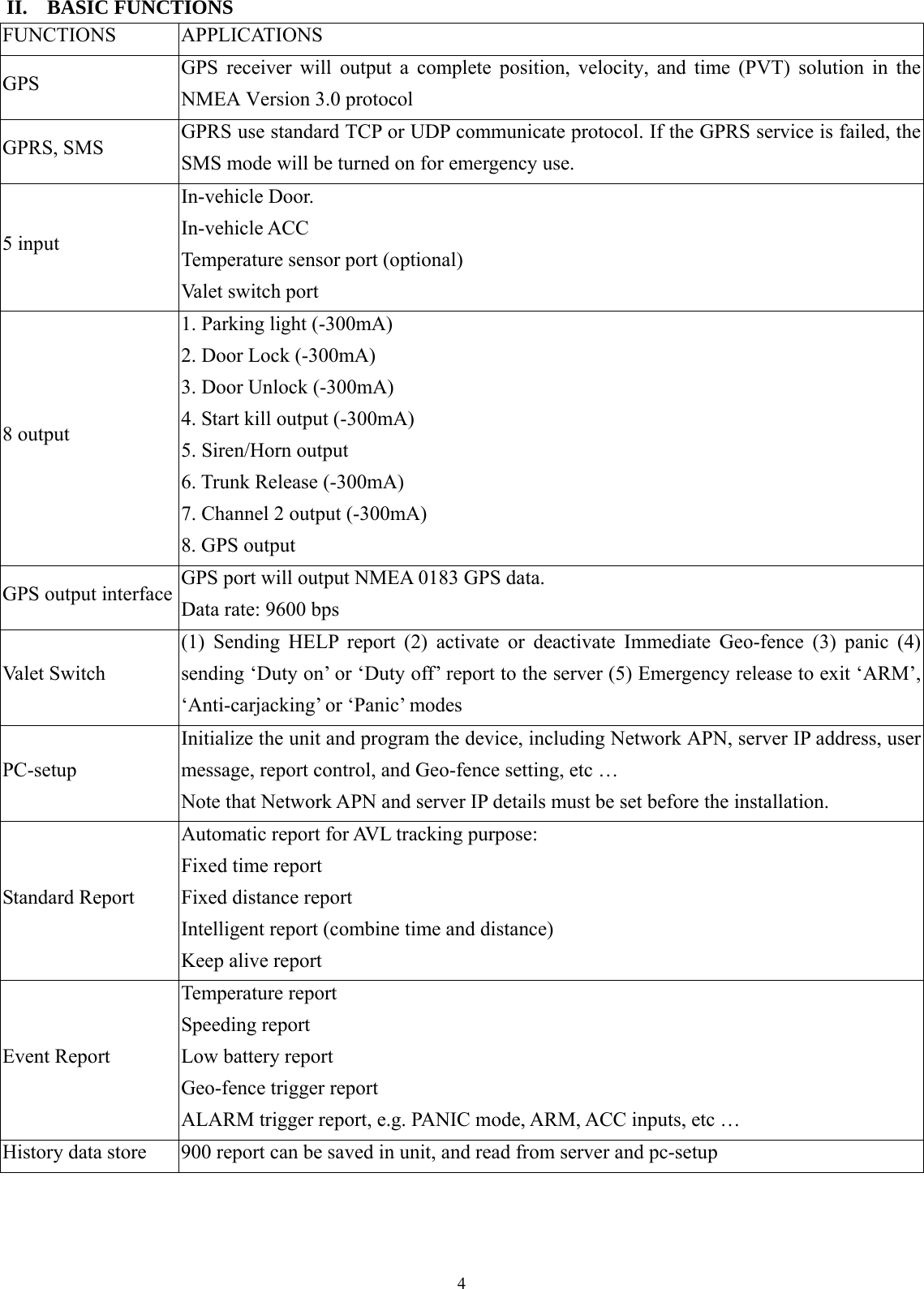
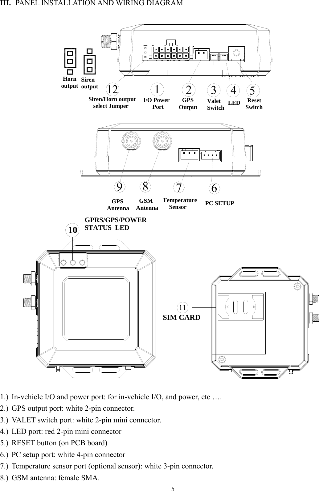
PORTMAN ELECTRONICS GT-3100 Economic Mini Tracking System User Manual
PORTMAN ELECTRONICS (DONGGUAN) CO., LTD. Economic Mini Tracking System
UserManual.wiki
>
PORTMAN ELECTRONICS
>
GT 3100 User Manual
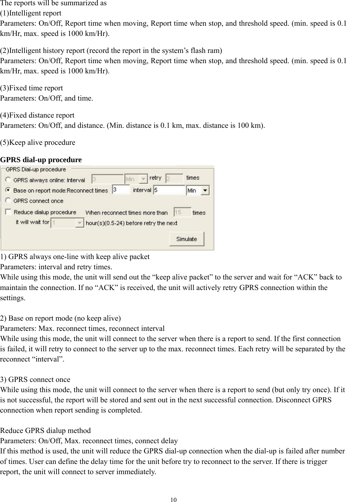
users manual
Navigation menu
Upload a User Manual
Namespaces
Wiki Guide
HTML
PDF
Info
Views
User Manual
Discussion / Help
Navigation
![7 C. MAIN INTERFACE 1. [User detail:] If the SIM card is password protected, user can input the “SIM PIN” window to set password of SIM Card. Set UNIT ID for the device.](https://usermanual.wiki/PORTMAN-ELECTRONICS/GT-3100/User-Guide-800649-Page-8.png)
![9 2. [Geo-fence:] 4 circular, 5 rectangle and 20 point Geo-fence areas can be set. When UNIT is out of these predefined zones, a report will be generated. When self Geo-fence is activated, It will record the current position as the origin and use the predefined distance for the radius to enable a circular Geo-fence. Origin\Upright point\Downright point has the format: N2446.5321E12120.4231 (21 fixed digits) Radius has the format: User can input the circular radius from 0.1 to 1000 (in km). 3. [Report:] Automatic report can be configured in this section. To activate the function(s), please select “√” in checkbox and fill in data in the textbox.](https://usermanual.wiki/PORTMAN-ELECTRONICS/GT-3100/User-Guide-800649-Page-10.png)
![11Simulate Click this buttons, it will base on the configurations to generate an approximate maximum dial-up numbers within 24 hrs. Therefore, user can predict the worst case dial-up connection if the server link is dead or GPRS disconnected. Special command for SMS mode: If the GT3100 is not in the GPRS online status, user can send command &&Y02 or &&Y04 to ask unit to connect to server. This command can be sent from any device via SMS; &&Y02: When received this command, system will actively try to connect to server in next 600 seconds. &&Y04,[connection time],[report interval]: For example: &&Y04, 3600, 60 When received this command, system will connect to server in the next 3600 seconds, and send one report out every 60 seconds. (6) Course change report (to send a report when the course change is bigger than the value set here) Parameters: On/Off, and course change in degree. (7) Temperature report Parameters: On/Off, and min. and max. Temperature. (8) Low battery warning report (to alert user when the external battery level is low) Parameters: On/Off, and warning battery level for report. For example, 50 to represent 50% lower level report. The system will ignore the parameter with a value ‘0’ to prevent continuous non-stop reporting. (9) Speeding report: (min. speed is 0.1 km/Hr, max. speed is 1000 km/Hr). Parameters: on/off, and speed 4. [Alarm REPORT setup] Alarm report(s) is also configurable. User can customize the events generated by the in-vehicle input or build in car alarm to be sent to the server. If the item(s) were selected (VALID), the related reports will be sent. Otherwise the report will be ignored even when an event is occurred internally. Sleep mode: ACC OFF without any trigger in 5 minutes, system will enter sleep mode, any trigger in anytime can awaken system.](https://usermanual.wiki/PORTMAN-ELECTRONICS/GT-3100/User-Guide-800649-Page-12.png)