PORTMAN ELECTRONICS GT-3200ST Basic Function tracking system User Manual
PORTMAN ELECTRONICS (DONGGUAN) CO., LTD. Basic Function tracking system
UserManual.wiki
>
PORTMAN ELECTRONICS
>
GT 3200ST User Manual
user manual
Navigation menu
Upload a User Manual
Namespaces
Wiki Guide
HTML
PDF
Info
Views
User Manual
Discussion / Help
Navigation

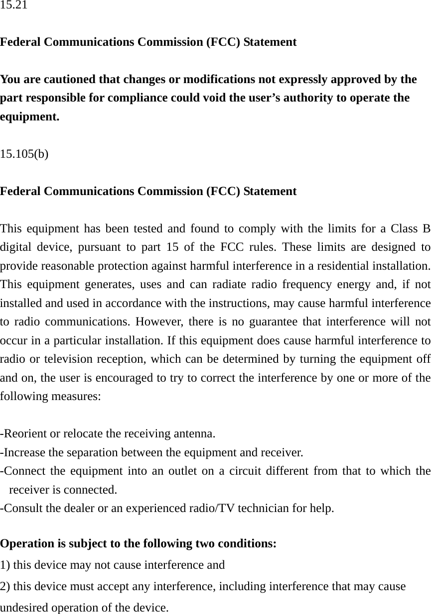
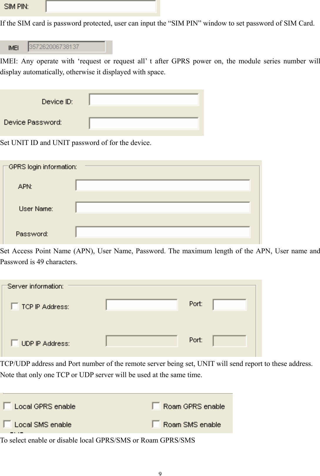
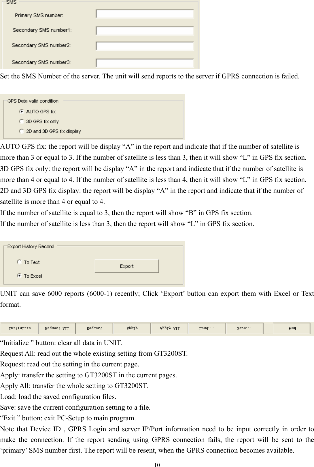
![8B. Version No. Checking The below interface will last until correct UNIT Version No. is checked. (You should run this program before turn on power of UNIT) C. MAIN INTERFACE 1. [User detail:]](https://usermanual.wiki/PORTMAN-ELECTRONICS/GT-3200ST/User-Guide-963231-Page-9.png)
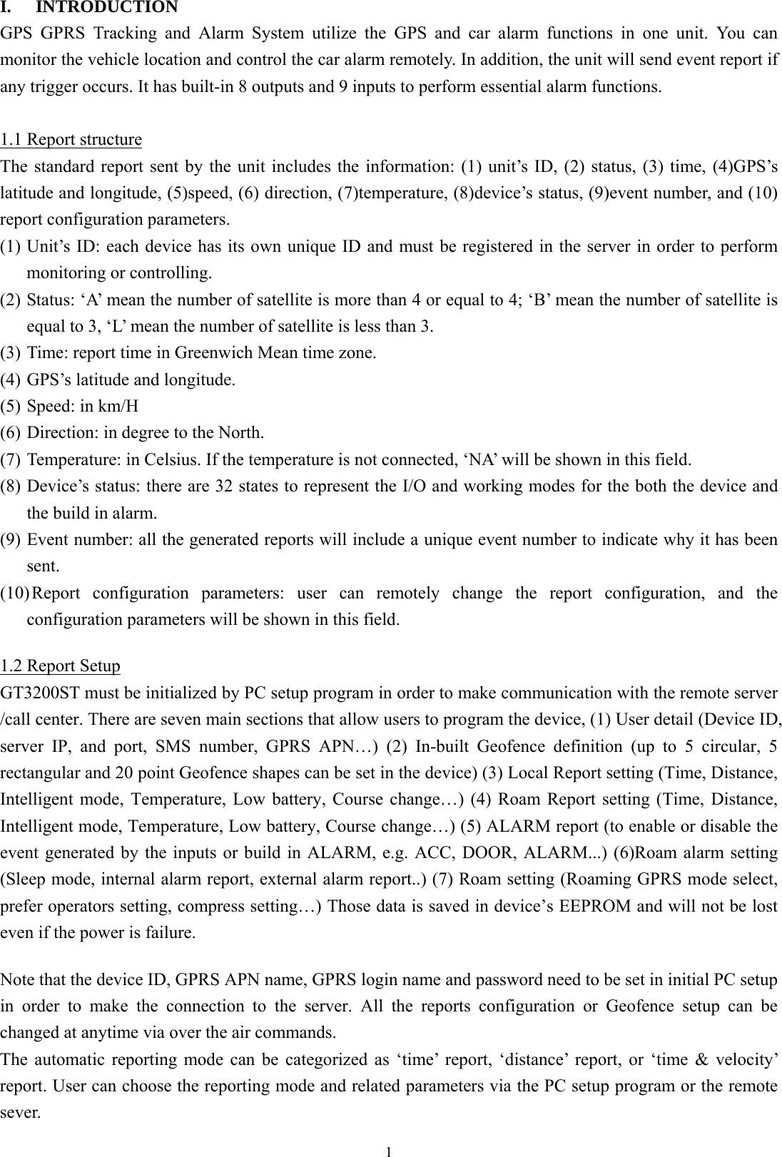
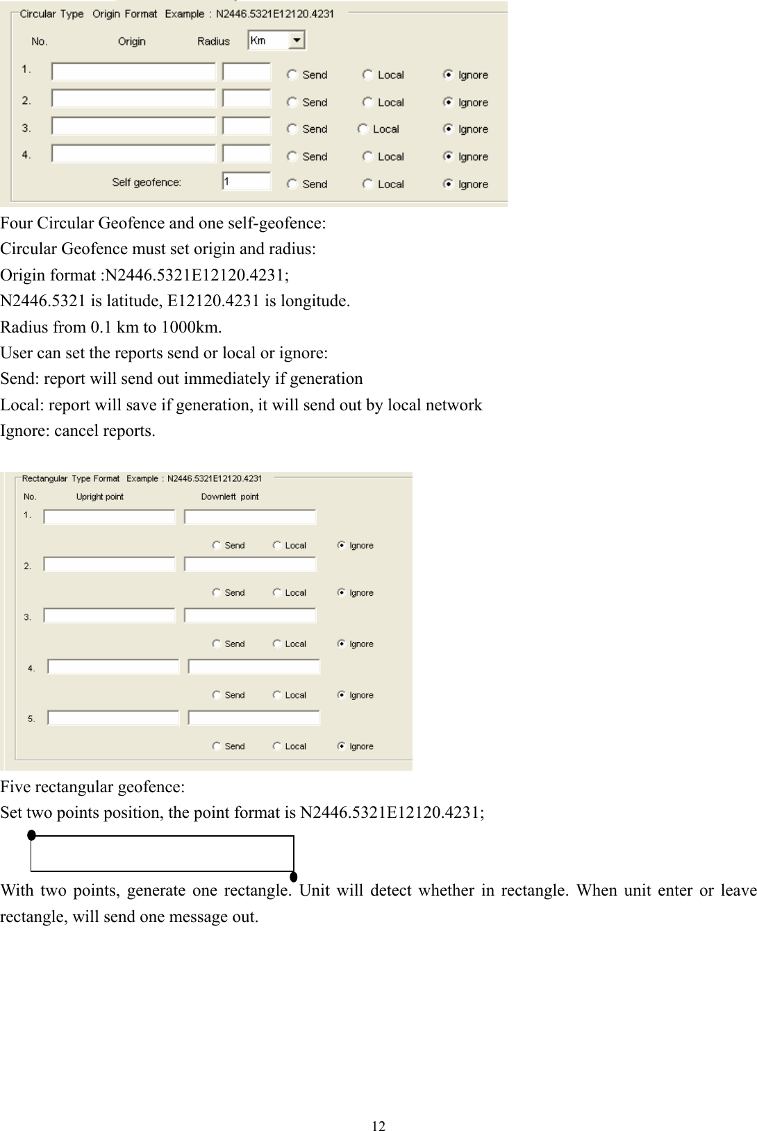
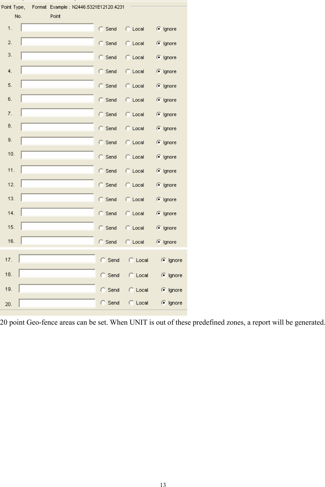
![112. [Geofence:]](https://usermanual.wiki/PORTMAN-ELECTRONICS/GT-3200ST/User-Guide-963231-Page-12.png)
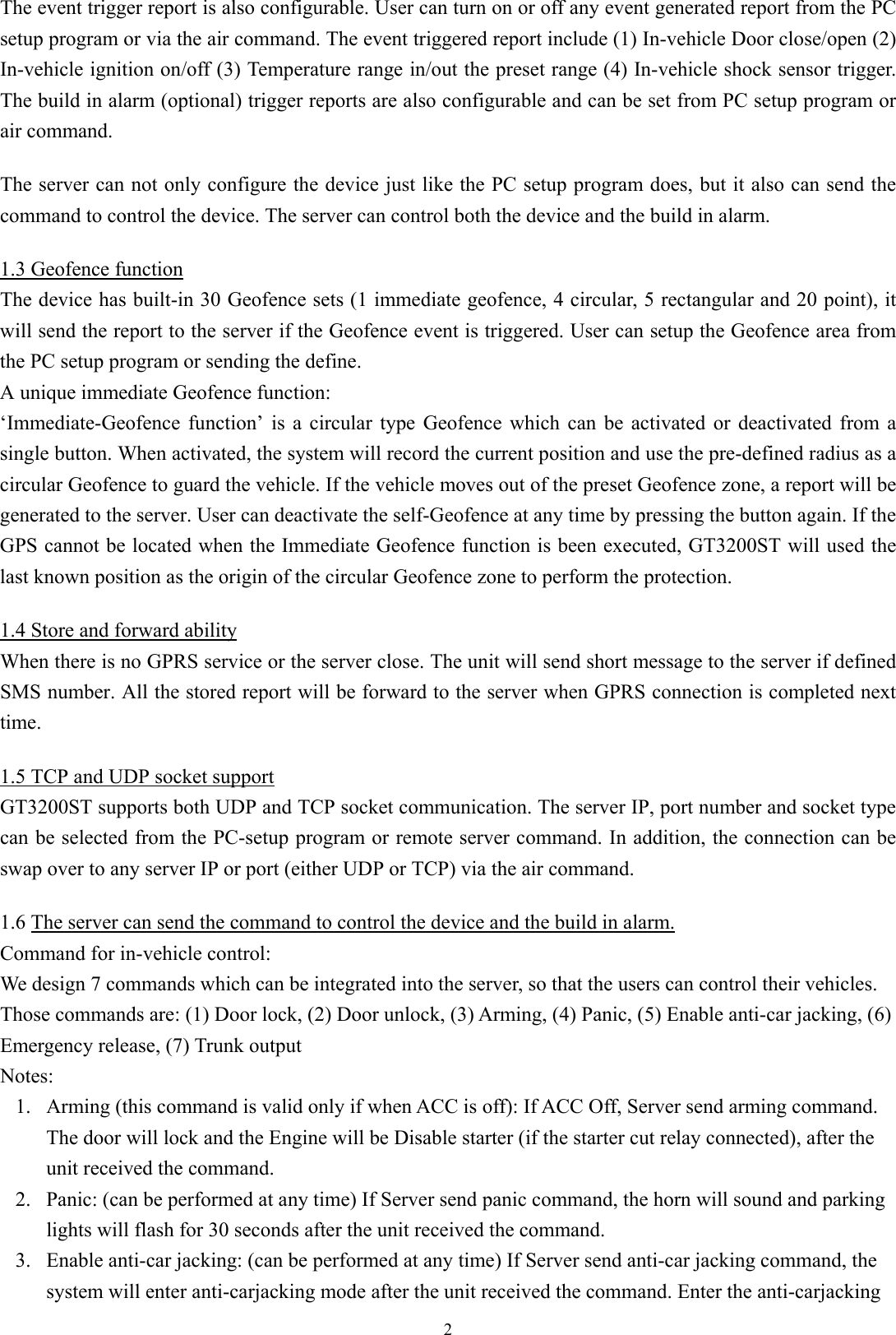
![143. [Local report]: Automatic report can be configured in this section. To activate the function(s), please select “√” in checkbox and fill in data in the textbox.](https://usermanual.wiki/PORTMAN-ELECTRONICS/GT-3200ST/User-Guide-963231-Page-15.png)
![15The reports will be summarized as (1) Intelligent report Parameters: On/Off, Report time when moving, Report time when stop, and threshold speed. Report when speed less than a preset value (refer the following 1.5 Km/Hr), and it will send stop report after a preset time (refer the following 120Sec). (min. speed is 0.1 km/Hr, max. speed is 1000 km/Hr). (2) Intelligent history report (record the report in the system’s flash ram) Parameters: On/Off, Report time when moving, Report time when stop, and threshold speed. (min. speed is 0.1 km/Hr, max. speed is 1000 km/Hr). (3) IO connect selection Parameters: to select either temperature sensor or AD1 (4) Temperature report Parameters: On/Off, and min. and max. temperature. (5) AD detect report (AD1) [on/off] SEND REPORT IF ADC1 LESS THAN [min voltage] V for [debounce time] SEC, RESEND PER [resend time] SEC [on/off] SEND REPORT IF ADC1 MORE THAN [max voltage] V for [debounce time] SEC, RESEND PER [resend time] SEC [on/off] SEND REPORT IF ADC1 GO UP [up voltage] V for [debounce time] SEC [on/off] SEND REPORT IF ADC1 GO DOWN [down voltage] V for [debounce time] SEC [on/off] SEND REPORT IF ADC1 ENTER/EXIT [min voltage] V TO [max voltage] V for [debounce time] SEC Note: AD1 input voltage range is 0~3.30v, it must connect a resistance to share the voltage if the detected voltage higher than 3.30v.](https://usermanual.wiki/PORTMAN-ELECTRONICS/GT-3200ST/User-Guide-963231-Page-16.png)
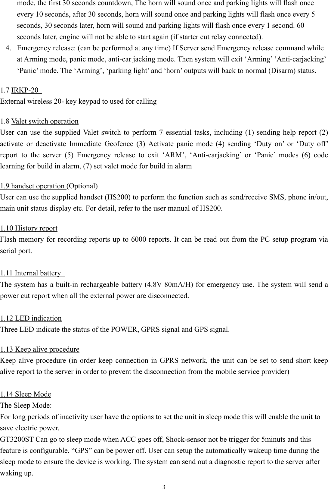
![16(6) AD detect report (AD2) [on/off] SEND REPORT IF ADC2 LESS THAN [min voltage] V for [debounce time] SEC, RESEND PER [resend time] SEC [on/off] SEND REPORT IF ADC2 MORE THAN [max voltage] V for [debounce time] SEC, RESEND PER [resend time] SEC [on/off] SEND REPORT IF ADC2 GO UP [up voltage] V for [debounce time] SEC [on/off] SEND REPORT IF ADC2 GO DOWN [down voltage] V for [debounce time] SEC [on/off] SEND REPORT IF ADC2 ENTER/EXIT [min voltage] V TO [max voltage] V for [debounce time] SEC Note: AD2 input voltage range is 0~3.30v, it must connect a resistance to share the voltage if the detected voltage higher than 3.30v. (7) Fixed time report Parameters: On/Off, and time. (8) Fixed distance report Parameters: On/Off, and distance. (min. distance is 0.1 km, max. distance is 100 km). (9) Course change report (to send a report when the course change is bigger than the value set here) Parameters: On/Off, course change in degree and debounce time. (10) Low battery warning report (to alert user when the external battery level is low) Parameters: On/Off, and warning battery level for report. For example, 50 to represent 50% lower level report. The system will ignore the parameter with a value ‘0’ to prevent continuous non-stop reporting. (11) Speed report Parameters: resend interval, threshold speed, over speed delay time, exit over speed delay time, alert when over speed and report send or ignore For example, if resend interval is 20 sec, enter over speed delay time is 20 sec, threshold speed is 110Km/h and exit over speed delay time is 2 sec. If vehicle speed over threshold speed 20seconds, system will send speed over report once interval 20 sec until exit speed over delay time 2 sec, the over speed report will stop to send. If alert when over speed has configured, then it will alert when speed over. (12) Crash report Parameters: on/off, and speed](https://usermanual.wiki/PORTMAN-ELECTRONICS/GT-3200ST/User-Guide-963231-Page-17.png)
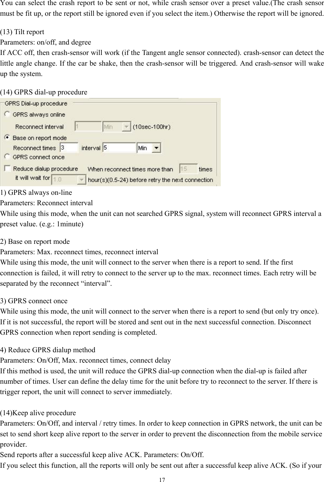
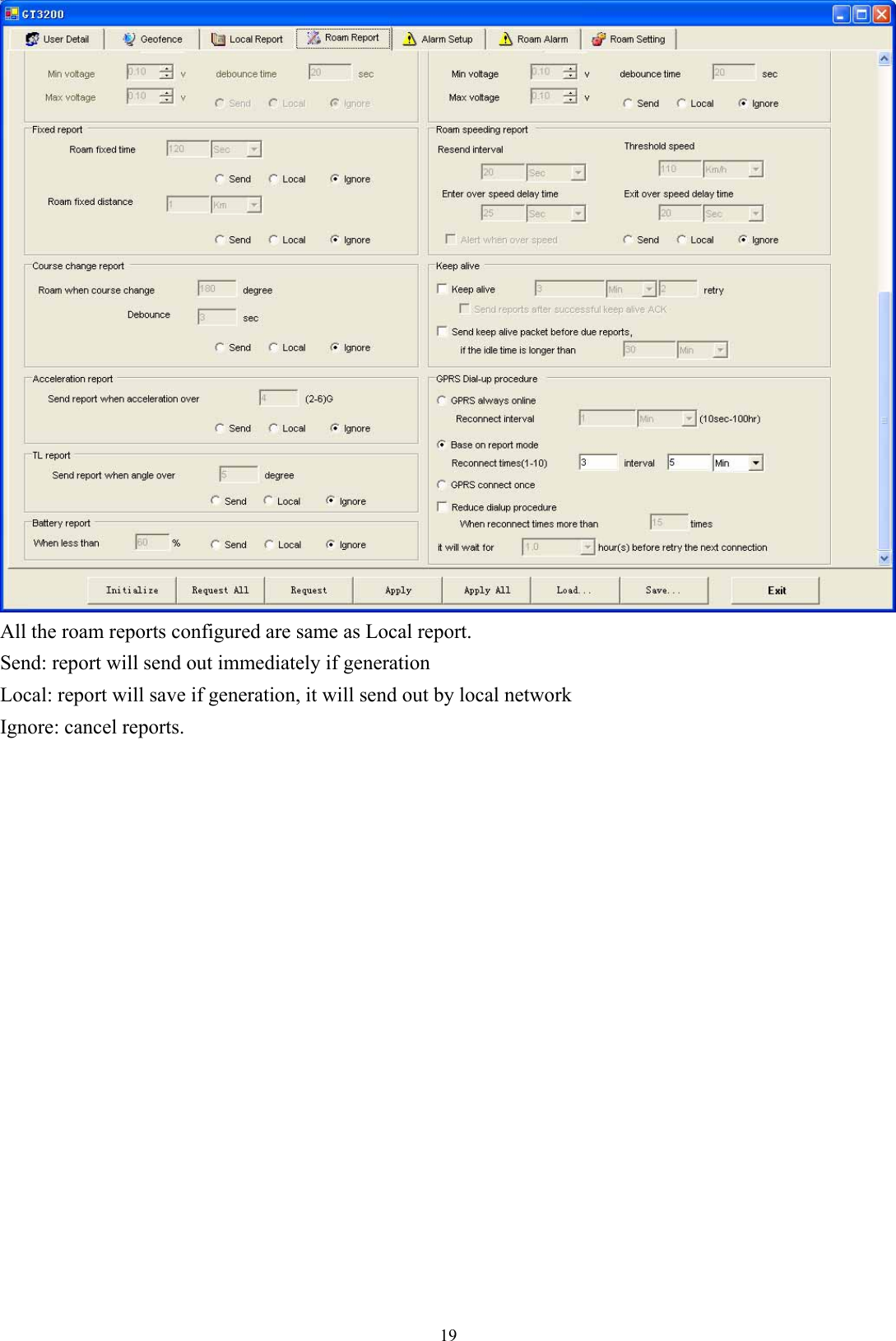
![18keep alive time is shorter then select this function will be OK.) This function is very useful while using UDP to prevent report lost. Send a keep alive packet right before a due reports if no data stream within certain time: Parameters: On/Off, and idle time. Some GSM provider might cut connection, if there is no data within certain time. It might result report lost in this “fake connection” duration. For example, you can set parameters in this region, ex 20 mins. (it means if the unit did not send any data in this 20 mins (including keep alive or normal reports) ), then it will send a keep alive packet to check if the GPRS connection is valid or not. If not, it will actively reconnect to GPRS network. Special command for SMS mode: If the GT3200ST is not in the GPRS online status, user can send command &&Y02 or &&Y04 to ask unit to connect to server. This command can be sent from any device via SMS; &&Y02: When received this command, system will actively try to connect to server in next 600 seconds. &&Y04,[connection time],[report interval]: For example: &&Y04, 3600, 60 When received this command, system will connect to server in the next 3600 seconds, and send one report out every 60 seconds. 4. [Roam report]](https://usermanual.wiki/PORTMAN-ELECTRONICS/GT-3200ST/User-Guide-963231-Page-19.png)
![205. [Alarm REPORT setup] Alarm report(s) is also configurable. User can customize the events generated by the in-vehicle input or build in car alarm to be sent to the server. If the item(s) be selected (VALID), the related reports will be sent. Otherwise the report will be ignored even when an event is occurred internally. Also build in car alarm function can be set on here. If input 3 with distance is selected, system will send the distance report every time ACC ON to ACC OFF, for example: %%GT3200ST,A,070521024400,N2240.8929E11359.2030,000,270,NA,D7000000,254,CFG:5, CFG:5 means the current ACC ON to ACC OFF distance is 5km. Sleep mode (when ACC OFF) (1) GT3200ST can go to sleep mode when ACC goes off and crash-sensor (and optional shock sensor) not be trigger for 5minuts. In sleep mode, GPS will be disabled. All the auto report (Time, Distance, Intelligent…) will not be send when ACC goes off. (2) During the sleep mode, the system can wait up automatically and send a wake up diagnostic report. The automatic wakeup time is configurable. (Minimum duration is 5 minutes; maximum duration is 1000 Hours). (3) If any of the inputs are triggered while in the sleep mode, the system will wake up automatic and then send reports to the server. The input triggers for waking the device up are selectable. If the GPRS connection is failed, for emergency purpose, GT3200ST will send out SMS report if number is defined. If select the item, when ACC off, system will cut power of handset, otherwise, system will not cut power of handset.](https://usermanual.wiki/PORTMAN-ELECTRONICS/GT-3200ST/User-Guide-963231-Page-21.png)
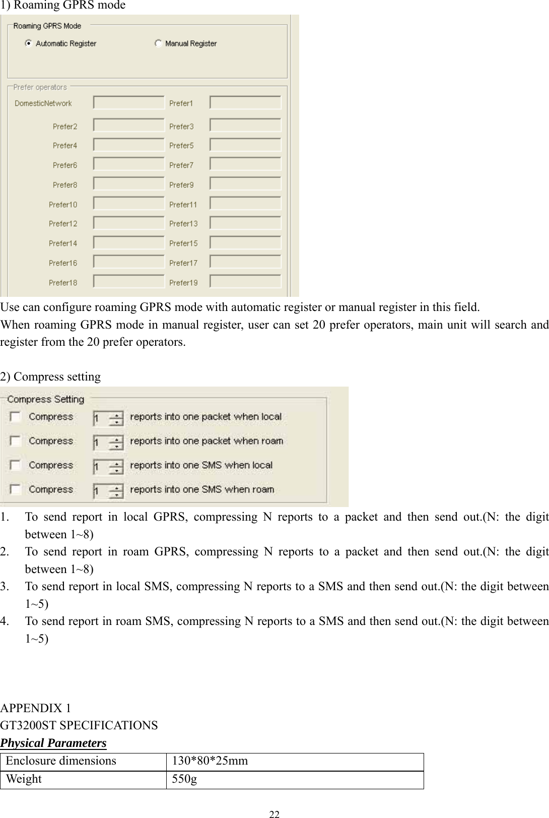
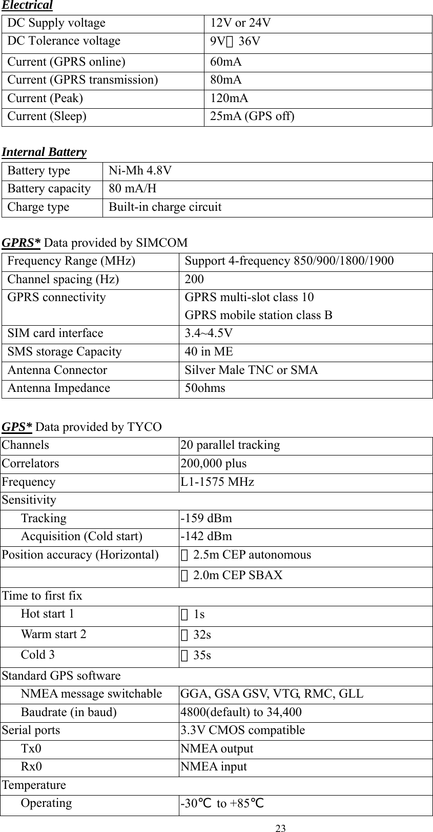
![216. [Roam Alarm REPORT setup] In roam alarm mode, use can set all the alarm reports send or local or ignore: Send: report will send out immediately if generation Local: report will save if generation, it will send out by local network Ignore: cancel reports. 7. [Roam setting]](https://usermanual.wiki/PORTMAN-ELECTRONICS/GT-3200ST/User-Guide-963231-Page-22.png)