PORTMAN ELECTRONICS HEU-100 HEAVY EQUIPMENT UNIT User Manual
PORTMAN ELECTRONICS (DONGGUAN) CO., LTD. HEAVY EQUIPMENT UNIT Users Manual
UserManual.wiki
>
PORTMAN ELECTRONICS
>
HEU 100 User Manual
Users Manual
Navigation menu
Upload a User Manual
Namespaces
Wiki Guide
HTML
PDF
Info
Views
User Manual
Discussion / Help
Navigation
![In Commercial Confidence 5B. Version No. Checking The below interface will last until correct HEU Version No. is checked. (You should run this program before turn on power of HEU) C. MAIN INTERFACE 1.[User detail]: (1) Set Device ID for HEU. The device must be unique in order to be identified by the server. (2) Set Access Point Name (APN), User Name (GPRS), Password (GPRS). The maximum length of the APN, User name and Password is 49 characters. Note that, some service providers do not require USER name or PASSWORD, hence, user can leave blank in this section. (3) “TCP/UDP” address and Port number of alarm center being set, HEU will send message to these address. Note that only one TCP or UDP server will be used at the same time. (4) HEU can save 900 reports (900-1) recently; Click ‘Export’ button can export them into Excel or Notepad.](https://usermanual.wiki/PORTMAN-ELECTRONICS/HEU-100/User-Guide-671865-Page-6.png)
![In Commercial Confidence 6 2. [Geofence]: Setup the Geofence (in circular shape) parameters in this window. The format will be center of the Geofence and the related radius. User can also set the radius for the self-Geofence in this field. The self-Geofence can be activated/deactivated from the 2 button LED switch. 3.[Report]:](https://usermanual.wiki/PORTMAN-ELECTRONICS/HEU-100/User-Guide-671865-Page-7.png)
![In Commercial Confidence 7In the working mode, the system will use the configurations as defined in this section. To activate the automatic report, please select “√” in checkbox and fill in data in the textbox. The reports will be summarized as (1) Intelligent report Parameters: On/Off, Report time when moving, Report time when stop, and Moving Speed (min. Speed is 0.1 km/Hr, max. Speed is 1000 km/Hr). (2) Intelligent history report (record the report in the system’s flash ram) Parameters: On/Off, Report time when moving, Report time when stop, and Moving Speed (min. Speed is 0.1 km/Hr, max. Speed is 1000 km/Hr). (3) Fixed time report Parameters: On/Off, and time. (4) Fixed distance report Parameters: On/Off, and distance. (min. distance is 0.1 km, max. distance is 100 km). (5) Course change report Parameters: On/Off, and course change in degree. (6) Low battery warning report (to alert user when the battery level is low) Parameters: On/Off, and warning battery level for report. For example, 60 to represent 60% lower level report. The system will ignore the parameter with a value ‘0’ to prevent continuous non-stop reporting. Power cut report: default is on. When the external power is cut, a POWER CUT report will be sent to the server. (7) Speeding report: (min. speed is 0.1 km/Hr, max. speed is 1000 km/Hr). Parameters: on/off, and speed 4.[Trigger report and sleep mode setup]](https://usermanual.wiki/PORTMAN-ELECTRONICS/HEU-100/User-Guide-671865-Page-8.png)
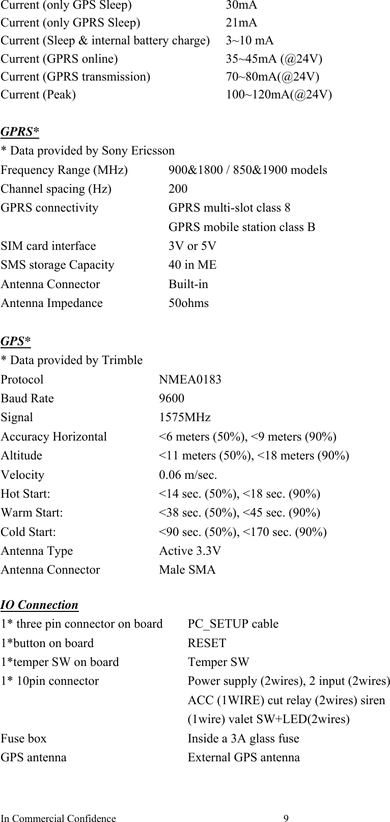
![In Commercial Confidence 8ALARM report Alarm report(s) is also configurable. User can customize the events generated by the in-vehicle input to be sent to the server. To enable the particular trigger reports by click the box. Sleep mode (when ACC OFF) (1) HEU can go to sleep mode when ACC goes off. (The average lasting time after ACC OFF is 5 minutes.) In sleep mode, both GPS & GPRS will be disabled. All the auto report (Time, Distance, Intelligent…) will not be send when ACC goes off. (2) During the sleep mode, the system can wait up automatically and send a wake up diagnostic report. (3) The automatic wakeup time is configurable. (Minimum duration is 5 minutes; maximum duration is 1000 Hours). (4) If any of the inputs are triggered while in the sleep mode, the system will wake up automatic report and then send reports to the server. The input triggers for waking the device up are selectable. If the GPRS connection is failed, for emergency purpose, HEU will send out SMS report if number is defined. [Button description] (1)Initialize: clear all saved parameters in HEU. (2) Request All: request all parameters that is saved previously in HEU (3) Request: request parameters in the current page (4) Apply: set the parameters in the current page (5) Apply All: save all the parameters into HEU (6) Load: load the saved configuration file (*.heu) (7) Save: save the parameters into a files (*.heu). (8) Exit: exit the PC-Setup program; the system will exit the PC setup mode into the working mode. INTERNAL BATTERY PROTECT MECHANISM: To protect internal battery, we added a mechanism to HEU, when the internal battery voltage drop to 9v,HEU will keep to detect battery voltage for 2 minutes, if the battery voltage keep 9v continuously during this 2 minutes period. HEU will send a “battery shut down event” to server to notice user. After this event is sending out, HEU only can work another 30 minutes. After HEU goes into “battery shut down” mode, HEU will check the battery continuously, if the battery charges to 12v for 2 hours, it can work again. APPENDIX I HEUSPECIFICATIONS Physical Parameters Enclosure dimensions 160(L)*113(W)*73(H) Weight About 600g Electrical Rated DC Supply voltage 24V DC supply voltage range 10V-40V Battery charge current 20-100mA Current (Sleep) 7mA (Both GPS and GPRS are off)](https://usermanual.wiki/PORTMAN-ELECTRONICS/HEU-100/User-Guide-671865-Page-9.png)