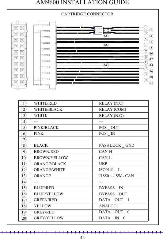
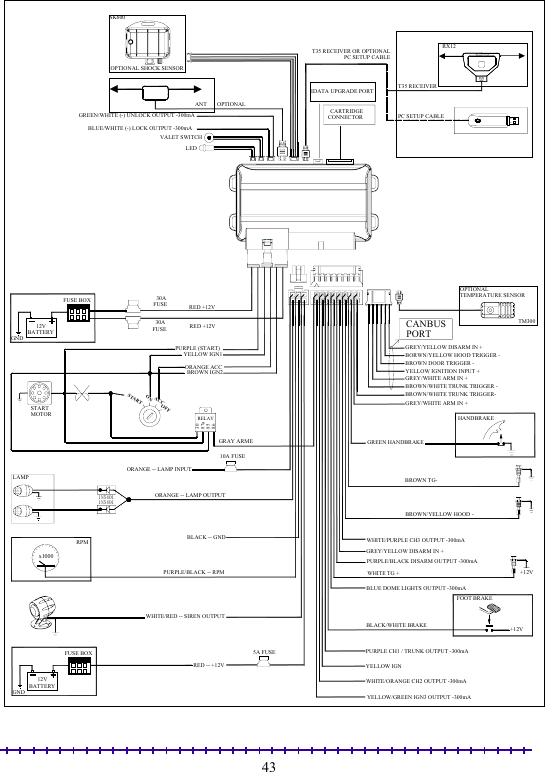
PORTMAN ELECTRONICS T35-915 T35 two way transmitter User Manual AM9600 V1 9 t35t36

PORTMAN ELECTRONICS (DONGGUAN) CO., LTD. T35 two way transmitter AM9600 V1 9 t35t36

user manual

            PORTMAN SECURITY SYSTEMS, LTD ONE-WAY CAR ALARM TWO-WAY LCD CAR ALARM   Operation/ Installation Manual    AM9600T35/T36    01/13/2010 Version 1.9
                                                                                                              1 T35 (Two way)                                              T36 (One way)             T35 (Two way) T36 (One way)  Functions Conditions Press button 1 once Arm and lock doors Car finder with sound Stop alarm temporarily Remote lock doors Disarmed and Ignition OFFArmed Sounding  While driving Press and hold button 1 for 2 sec.  Remote Panic  Anytime Press button 2 once Disarm/unlock Stop alarm temporarily Remote unlock doors Armed Sounding While driving Press and hold button 2 for 2 sec.  All door unlock/disarm  Arming Press and hold button 3 for 2 sec.  Open trunk (Channel 1 output)  Anytime  Press button 4 once then press button 1 within 3 sec.  Active anti car hijacking   While driving Press button 4 once then press button 2 within 3 sec.  Channel 2 output   Anytime Press button 4 once then press button 3 within 3 sec.  Channel 3 output   Anytime Press button 4 once then press button 4 within 3 sec.  Channel 4 output   Anytime
                                                                                                              2Press and hold button 4 for 2 sec.  Remote start on/off  When start procedure ready Press button 1 + 4 once together  Arm with bypass shock sensor Disarming and ignition OFF Press button 3 + 4 once together  Manual active ready mode Ignition on & disarming & handbrake on Press button 5 once then press button 1 within 3 sec. Press button  1 + 3 once together Silent arm  Disarmed and ignition OFF Press button 5 once then press button 2 within 3 sec. Press button  2 + 3 once together Silent disarm  Arming Press button 5 once then press button 3 within 3 sec. Press and hold button 1 + 3 for 2sec Silent arm with bypass ext. sensor  Disarmed and ignition OFF Press button 5 once then press button 4 within 3 sec. Press and hold button 3 + 4 for 2 sec Timer start on/off  When start procedure ready Press button 5 once then press button 5 within 3 sec. Press button  2 + 4 once together Valet mode on/off  Disarming Press button 5 once then press and hold button 1 for 2 sec. within 3 sec. (only T35) No alarm arm mode  Disarmed and ignition OFF Press button 5 once then press and hold button 2 for 2 sec. within 3 sec. (only T35) Car temperature monitor  Anytime Transmitter power on  Transmitter power off Press button 1+5 once together (only T35)  Transmitter power off  Transmitter power on
                                                                                                              3Press button 5 once then press and hold button 5 for 2 sec. within 3 sec. (only T35) Unit Program mode on  Ignition off & disarming & door open Unit Program mode off  Ignition off & disarming & door open Press and hold button 5 for 2 sec. (only T35)  Transmitter program mode on/off  Anytime Press button 4 once then press button 5 once within 3 sec.  (only T35) System status check  Anytime   Special function for T35 1.  Press button 1+5 to turn on /off transmitter power 2.  In disarm mode, if the transmitter without any operation within 1~9 days, transmitter will chirp bi-bi-bi-----for 5 times, then turn off the power, in this time, press button 1+5 to turn on /off transmitter power, if the transmitter in arm mode, the transmitter power can not be turned to off. 3.  If any button has been pressed exceed 10 seconds, transmitter will long chirp bi---bi---bi--- for 3 times, then light the icon (button1 or 2 or 3 or 4 or 5) to indicate which button has locked.  T35 BACKLIGHT: Button Functions  Color 1 once Arm and lock doors Car finder with sound Stop alarm temporarily Remote lock doors 1 for 2 sec.  Remote Panic 2 once Disarm/unlock Stop alarm temporarily Remote unlock doors 2 for 2 sec.  All door unlock/disarm 3 for 2 sec.  Open trunk (Channel 1 output) Green
                                                                                                              44 -> 1 within 3 sec.  Active anti car hijacking  4 -> 2 within 3 sec.  Channel 2 output  4 -> 3 within 3 sec.  Channel 3 output  4 -> 4 within 3 sec.  Channel 4 output  Blue 4 for 2 sec.  Remote start on/off  Green 1 + 4 once  Arm with bypass shock sensor 3 + 4 once  Manual active ready mode  Red 5 -> 1 within 3 sec.  Silent arm 5 -> 2 within 3 sec.  Silent disarm 5 -> 3 within 3 sec.  Silent arm with bypass ext. sensor  5 -> 4 within 3 sec.  Timer start on/off 5 -> 5 within 3 sec.  Valet mode on/off 5 -> 1 for 2 sec. within 3 sec.  No alarm arm mode 5 -> 2 for 2 sec. within 3 sec.   Car temperature monitor 5 -> 5 for 2 sec. within 3 sec.   Unit Program mode on Blue 5 for 2 sec.   Unit Program mode off  Green Transmitter power on  Red 1+4 for 2 sec. (only T35)  Transmitter power off  Red 5 for 2 sec. (only T35)  Transmitter program mode on/off  Green 4 -> 5 within 3 sec. (only T35)  System status check  Blue  While the backlight was turn to on, if without any action on T35 but alarm signal was received from unit, the Green backlight will turn to on (greenÆblueÆred…….)  ICON:
                                                                                                              5ICON Explanation  Indicates that you car is locked  Indicates that you car is unlocked  Indicate that your siren is turned on when locking /unlocking or alarm  Indicate that your remote-pager is sending signals to the controller unit   Indicate that the shock sensor is turned off  Indicate that the shock sensor has been triggered  Indicate alarm clock mode is on  Indication time hour, minute (24Hr)  Vehicle’s interior temperature Celsius / Fahrenheit units  Indicate your vehicle is in arm mode  Indicate your vehicle is in disarm mode  Indicate if you are in valet mode  Indicate that vibration mode is on    Indicate channel output. (CH2, CH3, CH4… output function)
                                                                                                              6 Indicate that your trunk is open  Indicate that your hood is open  Display remaining battery life  Indicate that your vehicle door is open  Indicate the turbo mode is on  Indicate function transfer and setting mode  Indicate the ignition key on trigger  Indicate your vehicle is in remote-start mode Indicate timer start mode is on  TWO WAY TRANSMITTER T35 SETTING FUNCTION Button Function  Setting Press 5 for 2 sec.  Enter Program mode   Anytime Press 5 once  Enter time of hour setting  Press button 1 for time add Press button 2 for time reduce Press 5 once  Enter time of minute setting  Press button 1 for time add Press button 2 for time reduce Press 5 once  Temperature’s unit & setting℃℉  Press button 1 for set ℃ Press button 2 for set ℉ Press 5 once  Alarm clock ON/OFF  Press button 1 for alarm clock on Press button 2 for alarm clock off Press 5 once  Enter clock hour setting  Press button 1 for time add Press button 2 for time reduce
                                                                                                              7Press 5 once  Enter clock minute setting  Press button 1 for time add Press button 2 for time reduce Press 5 once  Setting backlight ON/OFF  Press button 1 to turn on backlight Press button 2 to turn off backlight Press 5 once  Vibration motor ON/OFF  Press button 1 for vibration on Press button 2 for vibration off Press 5 once  Arm/disarm siren chirp ON/OFF Press button 1 for siren chirp on Press button 2 for siren chirp off Press 5 once  Setting shock sensor bypass ON/OFF Press button 1 for shock bypass on Press button 2 for shock bypass off Press 5 once  Auto power-off setting  Press button 1 for day increase Press button 2 for day reduce Press 5 for 2 sec.  Exit Program mode  Program mode  TWO WAY TRANSMITTER T35 SETTING OPERATION: Anytime Press 5 for 2 sec., the transmitter will enter program setting mode, then the ICON of the time clock, alarm clock, shock bypass, temperature unit, siren and vibrate, backlight LED will begin to flash. The first setting item is HOUR, using button 1 or button 2 to adjust up and down the HOUR. After setting the HOUR, Press button 5 once to minute setting, the operation is the same as HOUR setting. Then the time clock setting is over, press button 5 once will enter the temperature unit setting, press button 1 set the temperature unit is  , press button 2 set ℃the temperature unit is  , After th℉e temperature unit setting, press button 5 once to alarm clock setting. If the alarm clock is setting ON, then auto entry the time clock setting, the procedure is the same as time clock setting. After the alarm clock setting, press button 5 once will enter the backlight LED setting; press button 1 to set the backlight LED function will ON, press button 2 set the backlight LED function will OFF (The backlight LED will not light when any button be pressed). After the backlight LED setting, press button 5 once will entry the vibration setting, press button 1 set the vibration function will ON (every trigger, the transmitter motor will continue running), press button 2 set the vibration function will OFF (every trigger, the transmitter motor will not running). After the vibration setting, press button 5 once will entry the sound setting, press button 1 set the sound
                                                                                                              8function will ON (the unit arm/disarm with chirp), press button 2 set the sound function will OFF (the unit arm/disarm without chirp). After the sound setting, press button 5 once will entry the shock bypass setting, press button 1 set the shock bypass function will ON (the unit arm with shock bypass), press button 2 set the shock bypass function will OFF (the unit arm without shock bypass), press button 5 once will entry auto power off within the preset day, press button 1 to increase power-off day or button 2 to reduce power-off day. (PF:00 means the transmitter has set without auto power-off function, PF:01~PF:09 means auto power off is 1~9 day).  TAKE TIME SETTING FOR EXAMPLE (FOR T35) Press 5 for 2 sec. to enter timer-setting mode, press button 1 for time add, press button 2 for time reduce, press button 5 to choose sub-setting, e.g. clock, hour, minute In clock setting mode, when clock set with any number but not “0”, the timer setting is valuable, or else timer setting is invaluable.  THE FUNCTION SETTING FOR USING THE TRANSMITTER   (FOR T35) Ignition OFF, disarming and door open, press and hold button 5 -> 5 for 2 sec. within 3 sec, the unit will enter function selection mode. If press and hold button5 -> 5 for 2 sec. within 3 sec and don’t enter the function selection mode successfully, T35 will chirp for 5 times to indicate the failure. At the same time, the Icon will show “FAIL” for 5 sec to indicate the reason for failure. After the 5 sec, the T35 screen will return to normal status.  ICON FOR INDICATION OF THE FAILURE AS BELOW: ICON Explanation  RF communication failed  The unit is not in disarming mode When both the transmitter of T35 and main unit enter in to the function selection mode successfully, the siren will chirp 3 times to indicate  that the main unit is under  function selection mode. Transmitter T35 also will chirp 3 times to indicate the good condition of communication. At the same time, the LCD will show as below:
                                                                                                              9 F1:01"means: already in the menus of the function selection and show  the First Status in the menus 1.  FUNCTION AS BELOW: Button Functions  Indication 1 once  Return to the above function selection page   “F1:13" Show the function code if success , for example: “F1:13" 2 once  Go to the next function selection page  “F1:02" Show the function code if success , for example: “F1:02" 3 once Skip to the menus of the function selection in next page (can be circulatory)  “F2:01" Show the function code if success , for example: “F2:01" Hold 1 for 2 sec. Turn the chose function to factory default and the main unit will operate this indication If success, siren chirp once, flash “SUC” for 3 times If failure, siren chirp twice, flash “FAIL” for 3 times Hold 2 for 2 sec. Turn the chose function to the second setting and the main unit will operate this indication  If success, siren chirp once, flash “SUC” for 3 times If failure, siren chirp twice, flash “FAIL” for 3 times Hold 3 for 2 sec. Turn the chose function to the third setting and the main unit will operate this indication If success, siren chirp once, flash “SUC” for 3 times If failure, siren chirp twice, flash “FAIL” for 3 times
                                                                                                              10Hold 4 for 2 sec. Turn the chose function to the Four setting and the main unit will operate this indication If success, siren chirp once, flash “SUC” for 3 times If failure, siren chirp twice, flash “FAIL” for 3 times Hold  5 for 2 sec. Exit the function choosing mode The siren will chirp 4 times to indicate that the main unit already get out function selection mode. Transmitter T35 also will chirp 4 times, flash “SUC” for 3 times to indicate the goods condition of communication. At the same time, the LCD returns to the normal status.  CANBUS FUNCTION 1.  ARM IN +: This input wire is normally connected to the vehicle’s CANBUS interface. The system will enter arming mode when it detected arming signal from the CANBUS interface.  2.  DISARM IN +: This input wire is normally connected to the vehicle’s CANBUS interface. The system will enter disarming mode when it detected disarming signal from the CANBUS interface.  3.  Hood trigger -: This input wire is normally connected to the vehicle’s CANBUS interface. The system will alarm in arming mode when it detected hood trigger signal from the CANBUS interface.  4.  Ignition input +: This input wire is normally connected to the vehicle’s CANBUS interface. If it detected ignition trigger signal from the CANBUS interface, then the system will alarm in arming mode, and the system will enter driving mode in disarming mode.  5.  Door trigger -: This input wire is normally connected to the vehicle’s CANBUS interface. The system will alarm in arming mode when it detected door trigger signal from the CANBUS interface.  6.  Trunk trigger -: This input wire is normally connected to the vehicle’s CANBUS interface. The system will alarm in arming mode when it detected trunk trigger signal from the CANBUS interface.
                                                                                                              11  PC SETUP FUNCTION When unit is in disarming & Door open status, Select the correct COM port number, and then set the following functions   Default: to use factory default setting Request: read out the setting in the current page. Apply: transfer the setting to unit in the current pages. Exit: exit PC-Setup program.
                                                                                                              12 BASIC CAR ALARM FUNCTION DESCRIPTION CODE LEARNING a.  When in disarmed mode. b.  Turn ignition ON, press Valet Switch 10 times within 8 seconds, siren will chirp 3 times, system will enter code-learning mode.  c.  Press any button on the transmitter, the siren will chirp accordingly for confirmation as soon as the transmitter is learned. For example, if the first transmitter is learned, the siren will chirp once. If the second transmitter is learned, the siren will chirp twice, etc… d.  Up to 3 transmitters can be programmed. e.  If one of the transmitters is programmed, the other transmitters must be reprogrammed within 8 seconds. Turn ignition OFF or 8 seconds later, system will exit code- learning mode.  ARMING a.  Press button 1. b.  Siren will chirp once. Parking lights will flash once. c.  Disables engine starter. d.  The doors will be locked after 0.5 seconds or 3.5 seconds. (see function selection J1-1)  e.  Two-way transmitter LCD screen will display arm and lock icon and chirp once. f.  LED will flash slowly  g.  After 3 seconds, all the sensors are armed. If the alarm shock sensor is triggered within 3 seconds, the siren will chirp twice and the circuit will be by-passed. Alarm will rearm by itself only when the sensor is stable for 2 seconds.   h.  If doors, trunk, hood are not closed enter arm, siren will chirp 5 time and the transmitter LCD screen will display doors, trunk, and hood open icon.  ARMING WITH BYPASSING SHOCK SENSOR a.  Press button 4 and button 1 together once  b.  Siren will chirp once then long chirp once and parking light will flash once, the system is entry in armed mode, all sensors will be bypassed in this arming cycle.  c.  Two-way transmitter LCD screen will chirp once and display arm, lock and shock bypass icon.
                                                                                                              13 SILENT ARMING a.  In disarming state, press button 3 and button 1 once together on T36 or press button 5 once then press button 1 once within 3 seconds. b.  Parking light will flash once.  c.  Disables engine starter. d.  Door will be locked at 0.5seconds or 3.5 seconds (See Function Selection J1-1). e.  Two-way transmitter LCD screen will display arm and lock icon. f.  After 3 seconds, all the sensors are armed. If the alarm shock sensor is triggered within 3 seconds, the siren will chirp twice and the circuit will be by-passed. Alarm will rearm by itself only when the sensor is stable for 2 seconds. g.  LED will flash slowly.  SILENT ARMING WITH BYPASSING SHOCK SENSOR a.  In disarming state, press and hold button 3 + 1 together for 2 seconds on T36 or press button 5 once then press button 3 once within 3 seconds.  b.  Parking light will flash once, the system is entry in silent armed mode, all sensors will be bypassed in this arming cycle.  c.  Two- way transmitter LCD will display arm and chirp once, lock and shock bypass icon.  HIDDEN ALARM ARMING (ONLY FOR T35) a.  First press button 5 then press and hold button 1 for 2 seconds within 3 seconds b.  Siren will chirp twice and parking light will flash twice, the system will entry in no alarm arming mode. c.  In this arming mode, the siren and parking light will not alarm if any sensor will be triggered, but the system will remain send trigger signal to the transmitter.  ALARM PERIOD AND SOUNDING CYCLE  a.  While arming, if any detector is triggered, the siren will sound 30 seconds (max) and the parking light will flash 30 seconds (max).  b.  For any single trigger, the siren will sound one cycle only. (One cycle is: sound 30 seconds and stop 3 seconds.) c.  For the same arming period, and for each single detector, the system can only be triggered (single trigger) at most 8 times.
                                                                                                              14d.  For each individual detector, the number of sounding cycle can be accumulated in the same arming period.  (E.g. If open the door, and let the siren sound 5 cycles, and close the door, the siren will stop sound, then if open the door again, it can only sound 3 cycles.) e.  After 8 cycles, the triggered detector will be bypassed. This detector will not be triggered again in the same arming period. f.  The system is disarmed; the all the detector is return normal status.  TRANSMITTER DISPLAY REPORT WHEN SYSTEM TRIGGER a.  The system is in arming status. b.  If the shock sensor is warned triggered, the unit will send the information to transmitter, the transmitter LCD screen will display shock sensor warn trigger icon and piezo will continue sound. c.  If the shock sensor or ext sensor is fully triggered, the unit will send the information to transmitter, the transmitter LCD screen will display shock sensor full trigger icon and piezo will continue sound. d.  If the door is triggered, the unit will send the information to transmitter, the transmitter LCD screen will display door trigger icon and piezo will continue sound. e.  If ignition has been triggered, the unit will send the information to transmitter, the transmitter LCD screen will display ignition trigger icon and piezo will sound continually. f.  If the trunk is triggered, the unit will send the information to transmitter, the transmitter LCD screen will display trunk trigger icon and piezo will continue sound. g.  If the hood is triggered, the unit will send the information to transmitter, the transmitter LCD screen will display hood trigger icon and piezo will continue sound. h.  The transmitter alarm display (icon flash and piezo sound) will continuously for 30 seconds (max), within 30 seconds, press button 1 or button 2 will stop alarm.  DISARMING  a.  Press button 2.  b.  Siren will chirp 3 times, parking lights will flash 3 times. If siren chirps 4 times and parking lights flash 4 times, which means the alarm has been triggered during arming state.  c.  Press button 3 and button 2 together once on T36 or press button 5 once then press button 2 once within 3 seconds on T35, the system will silent disarming, only parking light will flash indication.
                                                                                                              15d.  Doors will be unlocked after 0.5 seconds or 3.5 seconds (see function selection J1-1).  e.  If somewhere was triggered, the LED will flash to indicate as following:  Quick flash 2 times after a pause           Shock sensor or ext sensor full trigger Quick flash 3 times after a pause           Door trigger Quick flash 4 times after a pause           Trunk trigger Quick flash 5 times after a pause           Hood trigger Quick flash 6 times after a pause           IGN trigger f.  Two-way transmitter LCD screen will display the triggered zone icon and unlock icon. g.  Dome light will be ON for 30 seconds (if selective dome light output), and will be OFF when ignition ON.   AUTOMATIC REARMING (SEE FUNCTION SELECTION J1-7) After disarm, the system will be re-armed automatically or re-arm with door lock after 30 seconds if the ignition does not turn ON or the door is not open.  LAST DOOR ARMING (SEE FUNCTION SELECTION J1-6) a.  Turn ignition ON, then OFF and close the last door. After 30 seconds, the system will arm automatically or arm with door lock. b.  If one of the doors is opened during the above mentioned 30 seconds periods, system will postpone enter arming mode till all doors are closed.  SMART IMMOBILIZATION (SEE FUNCTION SELECTION J1-11) a.  When ignition is turned to OFF for 2 min, if the alarm is not armed, the engine will be cut automatically and cannot be restarted. LED will be ON for 0.5 seconds and then OFF for 3 seconds, and circle. b.  Exit auto-immobilization mode: when ignition OFF, press button 2 once, Or please perform OVERRIDE PROCEDURE.  2-STAGE SENSOR a.  If car receives a light shock, siren will chirp five times and parking lights will flash once for warning purpose. b.  If car receives a heavy signal, siren will sound and parking lights will flash for 30 seconds immediately.
                                                                                                              16 DOOR LOCK CONTROL (WHILE DRIVING) a.  Press button 1 to lock doors. The doors can be locked. b.  Press button 2 to unlock doors. The doors can be unlocked.  AUTOMATIC DOOR LOCK (SEE FUNCTION SELECTION J1-8)  When the system is disarming and the ignition turn from OFF to ON, door will lock after 15 seconds or door will lock with footbrake is press first.   AUTOMATIC DOOR UNLOCK (SEE FUNCTION SELECTION J1-9) When the ignition turns from ON to OFF, doors will automatically unlock.  SECOND UNLOCK (SEE FUNCTION SELECTION J2-4) If the system is selection second unlock on, press and hold button 2 for 2 seconds, the second unlock will output 300mA negative signal.  OPEN TRUNK (CHANNEL 1 OUTPUT) (SEE FUNCTION SELECTION J2-3 /J2-8) a.  Anytime, press and hold button 3 for 2 seconds will to open trunk (channel 1 output) (with 300mA negative output). b.  The two-way transmitter LCD screen will display channel 1 output icon. c.  If the system is in arming at this time, the trunk trigger, ext sensor is by-pass till the channel output off. After 4 seconds, the system is in arm mode again.  CHANNEL 2 OUTPUT (SEE FUNCTION SELECTION J2-4 /J2-11) a.  Anytime, first press button 4 once then press button 2 once within 3 seconds will to remote channel 2 output (with 300mA negative output). b.  The two-way transmitter LCD screen will display channel 2 output icon. c.  If the system is in arming at this time, the trunk trigger, ext sensor is by-pass till the channel output off. After 4 seconds, the system is in arm mode again.
                                                                                                              17 CHANNEL 3 OUTPUT (SEE FUNCTION SELECTION J2-5 /J2-12) a.  Anytime, first press button 4 once then press button 3 once within 3 seconds will to remote channel 3output (with 300mA negative output). b.  The two-way transmitter LCD screen will display channel 3 output icon. c.  If the system is in arming at this time, the trunk trigger, ext sensor is by-pass till the channel output off. After 4 seconds, the system is in arm mode again.  CHANNEL 4 OUTPUT (SEE FUNCTION SELECTION J2-6 / J2-13) a.  Anytime, first press button 4 once then press button 4 once within 3 seconds will to remote channel 4 output (with 300mA negative output). b.  The two-way transmitter LCD screen will display channel 4 output icon. c.  If the system is in arming at this time, the trunk trigger, ext sensor is by-pass till the channel output off. After 4 seconds, the system is in arm mode again.  PANIC MODE a.  Anytime press and hold button 1 for 2 seconds. The siren will sound and parking lights will flash for 30 seconds b.  The two-way transmitter LCD screen will display siren icon and sound. c.  Press button 1or 2 to stop the panic.  CAR FINDER a.  The system is armed. b.  Press button 1: siren will chirp 6 times, the parking lights will flash 12 times. At the same time, the door will lock. c.  Press button 2 to stop car finder and disarm.   SYSTEM’S STATUS CHECK  Anytime press button 4 once then press button 5 once within 3 seconds, the system’s present status and current temperature will be shown on two-way transmitter LCD screen for five seconds.
                                                                                                              18 POWER ON MEMORY This security system is equipped with circuitry that will allow the unit to remember its alarm status if the power is lost and then reconnected.  VALET MODE a.  The system is disarming, turn ignition ON, within 8 seconds press and hold valet switch 3 seconds for once or press button 2+4 once together on T36 or press button 5 twice within 3 seconds on T35. b.  LED will be constantly ON, the parking light will flash once. c.  The two-way transmitter LCD screen will display valet mode icon, which indicates that system enters valet mode.  d.  In VALET mode, siren will chirp once and parking lights will flash once when lock the door, and siren will chirp twice and parking lights will flash twice when unlock the door. e.  In Valet mode, there is no arm and trigger alarm function, and it cannot enter smart immobilization and anti car jacking. f.  Leave valet mode: press button 2+4 once together on T36 or press button 5 twice within 3 seconds on T35. g.  LED will be OFF, and the parking light will flash twice which indicates that system exit valet mode.  ANTI CAR JACKING (SEE FUNCTION SELECTION J2-1, 2) The system provides 3 ways to enter anti-car jacking mode.   For MODE A, there are three ways to enter anti carjacking: a.  When ignition ON, first press transmitter button 4 once then press button 1 once within 3 seconds to activate the anti carjacking. b.  When ignition ON, after the door is opened, the system will enter anti carjacking. Within 10 seconds, pressing button 1 once of the transmitter will bypass the action of opening the door, and the system will exit anti carjacking mode. And the parking will flash once and siren will chirp once. Or perform Emergency disarming to exit the anti car jacking mode, that is to say, Within 71 seconds press and hold valet switch once for one second to exit anti jacking mode.
                                                                                                              19c.  After turning ignition ON, the system will enter anti carjacking mode at once. Within 10 seconds, pressing button 1 once of the transmitter will bypass the action of turning ignition ON, and the system will exit anti carjacking mode. And the parking will flash once and siren will chirp once. Or perform Emergency disarming to exit the anti car jacking mode, that is to say, Within 71 seconds press and hold valet switch once for one second to exit anti jacking mode. For MODE B, there are two ways to enter anti carjacking: The above b and a ways are available for mode B. For MODE C, there is one way to enter anti carjacking: The above a way is available for mode C.  WHEN THE SYSTEM ENTERS ANTI CARJACKING MODE a.  From the beginning to 15 seconds, nothing happen. b.  From 16 to 30 seconds, the LED will blink slowly. c.  From 31 to 45 seconds, the LED will blink fast and the siren will chirp once per 2 seconds.  d.  Form 46 to 70 seconds, the LED will blink fast and the siren will chirp once per seconds. e.  After 71 seconds, the siren will sound and the parking light will flash continuously. The arming wire will output negative 300mA current.  f.  After turn ignition OFF, the siren will sound and the parking lights will flash for 3 minutes before they stop.  g.  Turn ignition ON again without exiting anti carjacking mode, the siren will sound and the parking lights will flash continuously again. TO EXIT: perform Emergency disarming to exit the antijacking  Note: when system entered anti car jacking, the transmitter cannot control the unit.  Emergency disarming (See Function Selection J1-13) Please refer to its instruction for emergency disarm the system as following:  1. SIMPLE WAY: Please turn ignition ON, press and hold valet switch once for 1 second. Siren will chirp 4 times and the parking lights will flash 4 times, which indicates that the system is disarmed.
                                                                                                              20 2. 2ND WAY:  Please refer 2-pin code override procedure:  2-PIN CODE OVERRIDE PROCEDURE:  a.  Turn ignition ON, press valet switch 5 times within 8 seconds. b.  After 8 seconds, the LED should stay ON solid for 5 seconds, after the 5 seconds LED begins to flash. c.  When the LED flashes the 1st number of the 2-pin code, turn ignition OFF. Then turn back ON to wait for LED to flash the 2nd number of the 2-pin code. When the LED flashes the2nd number of the 2-pin code, turn ignition OFF When complete, siren will sound 4 times and the parking lights will flash 4 times to indicate system override, which indicates that the system is disarmed. d.  If LED flashes over 12 times, it means the program exits override procedure.  e.  If failed the override procedure, will need to turn off the ignition and return to step a.    PROGRAM PERSONAL 2 PIN CODE (FACTORY DEFAULT SETTING 1,2) Pin code program procedure: (system disarmed) a.  Turn ignition ON, press valet switch 5 times within 8 seconds.  b.  After 8seconds, the LED should stay ON solid for 5 seconds, after the 5 seconds LED begins to flash. c.  To change the factory pin code setting.  Turn ignition OFF after the LED flashes the 1st pin code.  Then turn ignition back ON to wait for LED to flash the 2nd pin code. When the LED flashes the2nd number of the 2-pin code, Turn ignition OFF, If the pin code recognition failed, the system will exit pin code setting automatically.  d.  Then turn ignition ON, and set the pin code as the LED flashes your selected 1st pin, then turn ignition OFF.  Siren will sound with number of times to indicate new pin code for the system. Follow the same method for the 2nd pin code.  The new 2-pin code will be recorded in EEPRON IC when completed.  NOTE: If the 2nd pin code setting is incorrect then the system will default pin code setting. The PIN code should within 1~9, 0 is not acceptable, wrongly input will exit the mode.
                                                                                                              21 REMOTE ENGINE START FUNCTION DESCRIPTION RPM LEARNING (SEE FUNCTION SELECTION J3-4) a.  When the system is disarming and ignition ON, press valet switch 6 times within 10 seconds, the parking lights will flash twice to indicate that system has entered the RPM learning mode. b.  Start the engine, when the RPM level is stabilized, press and hold valet switch till the parking lights will flash twice and the siren will chirp twice, which indicates the RPM value has been memorized successfully. NOTE: The unit remote start defaults check mode is Voltage mode; before the system entry the RPM learning mode, user must connect the vehicle RPM wire to the unit and function selection must select the start check mode is RPM mode.   TURBO MODE (SEE FUNCTION SELECTION J3-11) a.  The turbo mode is used for protect the engine. b.  Before the ignition is turned from ON to OFF (ignition must be ON more than 10 seconds), the engine will not shutdown immediately, but continue remain running for 3 minutes. c.  The engine will stop running immediately if step foot brake or release hand brake.  Reservation procedure for manual gear car (See Function Selection J3-1, J3-2) a.  If the car is the manual gear car, the unit must to perform the reservation procedure before the remote engine start, the reservation procedure has two setting mode selection. b.  The manual setting mode operation is following: c.  When the engine running, before you turn ignition OFF to stop the engine, pulls up the hand brake, release the foot brake. d.  Gear keeps in Empty position. e.  Press button 3+4 once together. f.  Turn ignition OFF, the engine will still remain running for 2 minutes. Within 2 minutes, open and close the door, the parking light will flash twice indicate that the reservation procedure is successful.
                                                                                                              22g.  In auto pre-set setting mode, when the engine running, Engine will automatically running 2 minutes after ignition off as reservation. Within 2 minutes, open and close the door, the parking light will flash twice indicate that the reservation procedure is successful. h.  If reservation produce is failed, or within 2 minutes no any action, the parking light will flash four times indication, then you must perform the step again. i.  Turn ignition ON, or open the hood, or press the foot brake, or pull down the hand brake will cause the unit to exit the reservation mode.  REMOTE START OPERATION Remote start activation: The following inputs will activate the Remote Start sequence and if a successful start enters the ‘RUN’ mode. Transmitter activation: the transmitter button 4 is press and hold 2 seconds when the ignition is OFF.  REMOTE START ‘RUN’ MODE: The ‘RUN’ mode begins when the unit has recognized a successful start.  a.  RUN time: The unit will keep the engine running for a maximum of 10 minutes (5, 20,30min option) from the time of a successful start. The same time, the two-way transmitter LCD screen will display running time and countdown running time. b.  The unit will exit the ‘RUN’ mode less than 10 minutes (5, 20,30min option) from the time of a successful start ONLY by Remote start de-activation input.  EXIT REMOTE START: The following inputs & operations will cause the unit to exit the ‘RUN’ mode and will not attempt to start again until the unit receives a remote start activation input. (if reservation procedure is successful, then if user: 1 pull down the handbrake; 2 press the foot brake; 3 open the hood, the reservation procedure will canceled when remote start.) a.  Transmitter de-activation: the Transmitter button 4 is press and hold 2 seconds of each other b.  The unit has reached the end of the 10 minute ‘RUN’ time (5, 20,30min option). c.  The unit detects a RPM signal at 8 times the programmed value (if RPM detect mode).
                                                                                                              23d.  Voltage input: in voltage mode the unit detects the voltage is drop 1.0V for more than 5 consecutively seconds during ‘RUN’ time (if voltage detect mode). e.  Unsuccessful start attempts: Three consecutively unsuccessful start attempts.   TIMER START MODE OPERATION a.  Timer mode activation: Anytime, press and hold button 3+4 together for 2 seconds on T36 or press button 5 once then press button 4 once within 3 seconds on T35. b.  The parking lights will flash 4 times as confirmation of activating ‘Timer mode’. c.  Timer mode start interval: The operator has the option to have the unit start every 12 or 1or 3 or 6 hours. Factory default is 12 Hour intervals. To select 12 or 1or 3 or 6 hour automatic start timer in feature programmable. d.  When timer modes start successful, the two-way transmitter LCD screen will display the “time”. NOTE1: This feature cannot be activated when the ignition is ON or the unit is in the ‘RUN’ mode. NOTE2: 3 Unsuccessful starts attempts will count as 1 successful start. The unit will attempt to start again at the next Timer mode start interval.   EXIT TIMER MODE: The following inputs & operations will cause the unit to exit the ‘TIMER’ mode. a.  Press and hold button 3+4 together for 2 seconds on T36 or press button 5 once then press button 4 once within 3 seconds on T35. b.  (+) Input on the foot brake input wire c.  (-) Input on the hand brake input wire d.  (-) Input on the hood pin wire e.  The ignition is ON while the unit is NOT in the ‘RUN’ mode. f.  The unit has called the Remote Start activation option additional times.  g.  ‘RUN’ mode is exited due to RPM signal 8 times programmed value (if RPM detect mode).  DIAGNOSTICS MODE When the engine stop running. Than the parking light will flash “N” times indicate the reason for shutdown. The indications are as follows:     1Flash      10(5, 20, 30) min run timer expired or transmitter activation input.     2Flashes     Low or No RPM signal received.
                                                                                                              24    3Flashes     hand brake input shut down.     4Flashes     foot brake or open hood input shut down.     5Flashes     High RPM signal over speed shut down     6Flashes     RPM has not learned.     7Flashes     voltage not raised or voltage has drop     8Flashes     manual gear car not perform the reservation procedure  RETURN TO FUNCTION FACTORY DEFAULT SETTING a.  In disarming status, turn Ignition OFF to ON 4 times, and ignition will stay in on position. b.  Press valet switch 12 times then press once again and hold it until 6 chirps with a long chirp is hearing then release the valet switch. c.  The all-programmable feature returns to factory default setting.  FUNCTION SELECTION a.  The function selection is programmable. Please follow the procedure.  b.  In disarming status, turn ignition on (must 5 seconds longer after last ignition off). c.  Within 8 seconds, press valet switch 3 times, then press once again and hold it for 3 seconds. System will chirp once to indicate entering function menu 1 selection, if not releasing the valet switch and hold on for 6 seconds, system will chirp twice to indicate entering function menu 2 selection, if still hold on for 9 seconds, system will chirp three times to indicate entering function menu 3 selection. d.  After entering manuals, presses Valet Switch to select the function to be changed within 20 seconds, system will chirp each time when Valet Switch is pressed and released. e.  When reach the times of selected function, press button 1 once or button 2 once or button 3 once or hold button 4 for 2 seconds (or press button 2 once to select variable value 1, press button 2 once again to select variable value 2, press button 2 once again to select variable value 3) of the remote control to select. The siren will chirp once when button 1 confirms the factory value, the siren will chirp twice when button 2 is the optional variable value 2. The siren will chirp three times when button 3 confirms the optional variable value 3, the siren will chirp four times when button 4 for 2 seconds confirms the optional variable value 4. f.  When exceed 20 seconds or turn ignition off, system will have a long beep and leave function selection mode.
                                                                                                              25FEATURE MENU 1:  Function selection  Pre set value (1 chirp) Variable 1 set-up  (2 chirps) Variable 2 set-up  (3 chirps) Variable 3 set-up  (4 chirps) J1-1  Lock/unlock timer  0.5 seconds  3.5 seconds     J1-2  Lock time  Same as J1  15 seconds  30 seconds   J1-3  Unlock pulse  1 pulse  2 pulse     J1-4  Arm/disarm with chirp  On   Off     J1-5  Arming delay time  3 seconds  30 seconds     J1-6  Last door arming  On, without lock  Off  On with lock   J1-7 Auto re-arm  On, without lock  Off  On with lock   J1-8  Automatic door lock  On  Off  Lock with footbrake   J1-9  Automatic door unlock  On  Off     J1-10  Alarm period  8 cycles  No limit     J1-11  Smart immobilized  On   Off     J1-12  Siren alarm duration  30 seconds  60 seconds     J1-13  Emergency override way  Simple way  2 pin code way    J1-14 Default setting  On        FEATURE MENU 2: Function selection  Pre set value(1 chirp) Variable 1 set-up (2 chirps)Variable 2 set-up  (3 chirps) Variable 3 set-up (4 chirps) J2-1  Anti car jacking function  Off On   J2-2  Anti car jacking mode  Mode C  Mode B  Mode A   J2-3  Programmable L1 output Trunk (Channel 1) output CH1 output and disarm Output pulse after start Output pulse during crank
                                                                                                              26J2-4  Programmable L2 output Channel 2 output Second unlock output CH2 output and disarm Output pulse before start J2-5  Programmable L3 output Channel 3 output Horn output CH3 output and disarm Output pulse after shutdown J2-6  Programmable L4 output Dome light output Channel 4 output CH4 output and disarm Remote start status output J2-8  Trunk (Channel 1) output Momentary output  Latched output  Latched output and reset with ignition ON 30 seconds timed J2-9  Horn timing  10ms  50ms 20ms 30ms J2-10  Ignition control dome light  On Off   J2-11  Channel 2 output  Momentary output  Latched output  Latched output and reset with ignition ON 30 seconds timed J2-12  Channel 3 output  Momentary output  Latched output  Latched output and reset with ignition ON 30 seconds timed J2-13  Channel 4 output  Momentary output  Latched output  Latched output and reset with ignition ON 30 seconds timed J2-14 Default setting On
                                                                                                              27 FEATURE MENU 3: Function selection  Pre set value (1 chirp) Variable 1 set-up (2 chirps) Variable 2 set-up (3 chirps) Variable 3 set-up (4 chirps)J3-1  Vehicle model  Automatic gear  Manual gear     J3-2  Manual gear reservation setting  Manual set  Auto pre-set     J3-3  Engine checking on/off  Engine checking on Engine checking off    J3-4  Check mode when start  Voltage checking type Tachometer checking type    J3-5  High/low voltage check level High voltage check level  Low voltage check level     J3-6  Cranking time   1.0s  0.6s  0.8s  2.0s J3-7 Gasoline/Diesel  Gasoline 2s warn-up timer Diesel 15s warn-up timer Diesel 30s warn-up timer Diesel 45s warn-up timer J3-8  Remote timer start  12H  1H   3H  6H J3-9  Warm-up duration  10 MIN  5MIN  20MIN  30MINJ3-10  Parking light output during running  Flash Steady on   J3-11 Turbo mode  Off  On     J3-12  External module type  Idata  Fortin  GP300   J3-13 Crank time mode of tachometer checking type 4 Cycle tachometer sensingSmart tachometer sensing 2 Cycle tachometer sensing  J3-14 Default setting  On
                                                                                                              28 FEATURE MENU 1 EXPLANATION: J1-1. LOCK/UNLOCK TIMER Pre-set: After press arm/disarm, the door is locked/unlocked output 0.5 seconds. Variable1: After press arm/disarm, the door is locked/unlocked output 3.5 seconds.  J1-2. LOCK TIMER Pre-set: same as J1. Variable 1: After press arm the door is locked output 15 seconds. Variable 2: After press arm the door is locked output 30 seconds.  J1-3. UNLOCK PULSE Pre-set: After presses disarm the door is unlocked output one pulse. Variable 1: After presses disarm the door is unlocked output two pulse.  J1-4. ARM/DISARM WITH CHIRP Pre-set: Arm/Disarm will have chirp indication.  Variable 1: Arm/Disarm will not have chirp indication.  J1-5. ARMING DELAY TIME Pre-set: delay 3s.  Variable 1: delay 30s.   J1-6. LAST DOOR ARMING Pre-set: Turn ignition ON to OFF and close the last door. After 30seconds, the system will arm itself without lock.  Variable1: Delete this feature. Variable2: Turn ignition ON to OFF and close the last door. After 30seconds, the system will arm itself with lock.
                                                                                                              29 J1-7. AUTO RE-ARM  Pre-set: The system is disarming without ignition ON or open the door. After 30seconds, the system will arm itself without lock.  Variable1: Delete this feature. Variable2: The system is disarming without ignition ON or open the door. After 30seconds, the system will arm itself with lock.  J1-8.AUTOMATIC DOOR LOCK Pre-set: When the ignition turns from OFF to ON, doors will lock after 15 seconds. Variable1: When the ignition turns from OFF to ON, door will not lock. Variable2: When the ignition turns from OFF to ON, door will lock with press the footbrake first.  J1-9.AUTOMATIC DOOR UNLOCK Pre-set: When the ignition turns from ON to OFF, doors will unlock immediately. Variable1: When the ignition turns from ON to OFF, door will not unlock.  J1-10.ALARM PERIOD Pre-set: the system can only be triggered at most 8 times. Variable1: the system’s triggered times is no limited.  J1-11.SMART IMMOBILIZE Pre-set: this feature exists. Variable 1: Delete this feature  J1-12. SIREN ALARM DURATION TIME  Pre-set: the system is triggered; the siren and parking light will alarm 30 seconds.   Variable 1: the system is triggered; the siren and parking light will alarm 60 seconds.
                                                                                                              30 J1-13. EMERGENCY OVERRIDE WAY  Pre-set: simple way.    Variable 1: 2 pin code way  J1-14. DEFAULT SETTING Pre-set: Return the feature menu 1 to the factory set-up.   FEATURE MENU 2 EXPLANATION: J2-1. ANTI CAR-HIJACKING Pre-set: Delete anti car-hijacking feature. Variable 1: Follow procedure to enter anti car-hijacking mode.  J2-2. ANTI CAR-HIJACKING MODE SELECT Pre-set: entry anti car-hijacking way is mode C. Variable 1: entry anti car-hijacking way is mode B. Variable 2: entry anti car-hijacking way is mode A.  J2-3.PROGRAMABLE L1 OUTPUT SELECT Pre-set: Trunk (channel 1) output. Variable1: Trunk (channel 1) output and disarming Variable2: output pulse after start. The wire will provide a 1 seconds -300mA pulsed ground output after the vehicle is started under control of the remote start unit. Typically this wire will be used to re-lock the vehicle doors if the doors unlock automatically when the factory anti-theft system is disarmed. Variable 3: output pulse during crank. The wire will provide a -300mA ground output while the starter output of the remote start unit is active. This output can be used to activate the Crank Low/Bulb Test wire found in some GM vehicles. This wire is also referred to as the ECM wake up wire in some Chrysler vehicles.
                                                                                                              31 J2-4. PROGRAMMABLE L2 OUTPUT SELECT Pre-set: channel 2 output. Variable1: seconds unlock output. Variable2: channel 2 output and disarming Variable 3: output pulse before start. The wire will provide a 1 seconds -300mA pulsed ground output 1.5 seconds before the remote start unit activates as well as when the transmitter is used to unlock the system to prevent false triggering of the factory alarm when the remote start unit engages or when the system is used to unlock the doors.  J2-5. PROGRAMMABLE L3 OUTPUT SELECT Pre-set: channel 3 output. Variable1: horn output. Note: horn output honk time is by J2-9 feature selection. Alarm output is on 10ms, off 200ms. Variable2: channel 3 output and disarming Variable 3: output pulse after shutdown. The wire will provide a 1 seconds -300mA pulsed ground output after the remote start unit shuts down. This output will occur regardless of whether the circuit times out or is manually terminated. Typically this output will be used to re-lock/re-arm the vehicle if the doors unlock automatically when the ignition circuit transitions to off or the factory anti-theft system is disarmed.  J2-6. PROGRAMMABLE L4 OUTPUT SELECT Pre-set: dome light output: when the system is alarming, the dome light ON as parking light. When disarm, dome light will ON until ignition ON (max 30 seconds). Variable1: channel 4 output.  Variable2: channel 4 output and disarm Variable 3: status continuant output when remote start.  J2-8. TRUNK (CHANNEL 1) OUTPUT MODE SELECT Pre-set: Momentary output: Anytime, press button 3 for 2sec. the CH1 will output-300mA constantly. Until the button 3 of transmitter are released.
                                                                                                              32Variable1: Latched output: this selection will output a –300mA signal from the channel 1 output as soon as the channel 1 button is pressed and will continue until the button is pressed again. Variable2: Latched output/reset with ignition ON: this selection will output a –300mA signal from the channel 1 output as soon as the channel 1 button is pressed but will reset or stop when the ignition is turned ON. Variable3: 30 seconds output: this selection will continue output a 30 seconds –300mA signal from the channel 1 output as soon as the channel 1 button is pressed.  J2-9.HORN TIMING SETTING Pre-set: If setting horn output, when the system is arm/disarm with horn honk, the horn honk default timing is 10ms. Variable1: the horn honk timing is 50ms. Variable2: the horn honk timing is 20ms. Variable3: the horn honk timing is 30ms.  J2-10. IGNITION CONTROL DOME LIGHT Pre-set: the dome light will off when ignition turn from off to on position, the dome light will illume (max: 30s) when ignition turn from on to off position. Variable 1: the dome light will not illume when ignition turn from on to off position.  J2-11. CHANNEL 2 OUTPUT MODE SELECT Pre-set: Momentary output: Anytime, within 3 seconds press button 4 once then press button 2 once, CH2 will output-300 mA. Variable1: Latched output: this selection will output a –300mA signal from the channel 2 output as soon as the channel 2 button is pressed and will continue until the button is pressed again. Variable2: Latched output/reset with ignition ON: this selection will output a –300mA signal from the channel 2 output as soon as the channel 2 button is pressed but will reset or stop when the ignition is turned ON. Variable3: 30 seconds output: this selection will continue output a 30 seconds –300mA signal from the channel 2 output as soon as the channel 2 button is pressed.
                                                                                                              33 J2-12. CHANNEL 3 OUTPUT MODE SELECT Pre-set: Momentary output: Anytime, within 3 seconds press button 4 once then press button 3 once, CH3 will output-300 mA Variable1: Latched output: this selection will output a –300mA signal from the channel 3 output as soon as the channel 3 button is pressed and will continue until the button is pressed again. Variable2: Latched output/reset with ignition ON: this selection will output a –300mA signal from the channel 3 output as soon as the channel 3 button is pressed but will reset or stop when the ignition is turned ON. Variable3: 30 seconds output: this selection will continue output a 30 seconds –300mA signal from the channel 3 output as soon as the channel 3 button is pressed.  J2-13.CHANNEL 4-OUTPUT MODE SELECT Pre-set: Momentary output: Anytime, within 3 seconds press button 4 once then press button 4, CH4 will output -300 Ma. Variable1: Latched output: this selection will output a –300mA signal from the channel 4 output as soon as the channel 4 button is pressed and will continue until the button is pressed again. Variable2: Latched output/reset with ignition ON: this selection will output a –300mA signal from the channel 4 output as soon as the channel 4 button is pressed but will reset or stop when the ignition is turned ON. Variable3: 30 seconds output: this selection will continue output a 30 seconds –300mA signal from the channel 4 output as soon as the channel 4 button is pressed.  J2-14. DEFAULT SETTING Pre-set: Return the feature menu 2 to the factory set-up.
                                                                                                              34FEATURE MENU 3 EXPLANATION: J3-1. VEHICLE MODE Pre-set: Automatic gear car: Without ‘ready mode’, remote start directly Variable1: Manual gear car: The ‘ready mode’ routine has been completed successfully system can remote start  J3-2. MANUAL GEAR CAR RESERVATION SETTING MODE Pre-set: Manual setting: When the engine running, press button 3+4 once to routine ‘ready mode’  Variable1: Auto pre-set setting: When the engine running exceed 10 seconds, ignition OFF will automatically routine ‘ready mode’   J3-3. ENGINE CHECK SELECTION WHEN REMOTE START Pre-set: Engine check ON: remote start successfully, to detect voltage rise or RPM signal. (if voltage rise or RPM signal is interrupted suddenly, the unit will start two times). Variable 1: Engine check OFF: remote start successfully, to detect voltage rise or RPM signal. (if voltage rise or RPM signal is interrupted suddenly, the unit will not start).  J3-4. CHECK MODE WHEN START Pre-set: Voltage checking type. Variable 1: RPM checking type.  J3-5. VOLTAGE CHECK LEVEL Pre-set: High voltage checks level.  Variable 1: Low voltage checks level.  J3-6. CRANK TIME SELECTION Pre-set: 1 second.  Variable1: 0.6 seconds.  Variable2: 0.8 second. Variable3: 2 seconds.
                                                                                                              35 J3-7. GASOLINE ENGINE/DIESEL ENGINE Pre-set: Gasoline engine without wait-to-start light 2 seconds warm-up timer. Variable1: Diesel engine without wait-to-start light 15 seconds warm-up timer. Variable2: Diesel engine without wait-to-start light 30 seconds warm -up timer. Variable3: Diesel engine without wait-to-start light 45 seconds warm -up timer.  J3-8. TIMER REMOTE START  Pre-set: interval time is 12 hours in timer remote start.  Variable1: interval time is 1 hour in timer remote start. Variable2: interval time is 3 hours in timer remote start.  Variable3: interval time is 6 hours in timer remote start.  J3-9.REMOTE START WARM-UP DURATION Pre-set: 10 minutes. Variable1: 5 minutes. Variable2: 20 minutes. Variable3: 30 minutes.  J3-10.PARKING LING OUTPUT DURING RUNNING MODE Pre-set: keeping flash during running mode. Variable1: keeping steady on during running mode.  J3-11. TURBO MODE Pre-set: Turbo mode selection off. Variable 1: Turbo mode selection on.  J3-12. EXTERNAL MODULE TYPE Pre-set: I data link mode Variable 1: Fortin mode; Variable 2: GP300
                                                                                                              36 J3-13. CRANK TIME MODE OF TACHOMETER CHECKING TYPE Pre-set: the engine remote start detect tachometer signal is 4-cycle pulse of tachometer.  Variable 1: the engine remote start detect tachometer signal is alterable by tachometer pulse frequency. Variable 2: the engine remote start detect tachometer signal is 2-cycle pulse of tachometer.  J3-14. DEFAULT SETTING Pre-set: Return the feature menu 3 to the factory set-up.    PHYSICAL PARAMETERS Enclosure dimensions  122*77*22mm Weight 120g  ELECTRICAL DC Supply voltage   12V DC Tolerance voltage   9V~16V Current (With RF)  <17mA Current (Without RF)  <10mA  RF PARAMETERS – T35 Frequency 910~918.4mHz Battery life  Half a year TX range (with RX12)  1000Meter Static current  <10uA
                                                                                                              37 INSTALLATION GUIDE FOR IDATALINK CONNECTED WITH AM9600  IDATALINK module (ADS-BLADE AL or ADS-BLADE TB) can be selected to work with AM9600 optional, the IDATALINK module can be used for bypass IMMOBILIZER SYSTEM for vehicle, and it can read RPM/DOOR/HAND BRAKE/FOOT BRAKE etc status, the IDATALINK module can remote control arm/disarm OEM alarm, it’s valuable for saving vehicle installation time.  The read out status is different for different IDATALINK module match with different vehicle, detailed information please login http://www.idatalink.com/ and read relevant content.  Download installation manual (example for Nissan vehicle)   1. Login http://store.idatalink.com/index.php?l=product_detail&p=70 2. Select    3. Download   then save it.  Note: quickly to find relative user guide in homepage:   Download IDATALINK explanation: To download IDATALINK program and buy “ADS-USB” as below picture:
                                                                                                              38 1.  download Weblink Updater software: http://www.idatalink.com/,  select SUPPORT──>then click Weblink plug-in 4.1 to download the software. 2.  Install Weblink plug-in 4.1 program 3.  While the program has installed, then insert ADS-BLADE AL into AM9600, and make sure the connection is good. Then connect AM9600 (IDATA UPGRADE PORT) to PC through ”ADS-USB” (AM9600 do not need power supply) 4.  to start “ADS Plug in 4.1” in start menu────Æselect   to quickly search module, while the module has searched out, the below interface will jump out:   Select “BLADE-AL(DL)-NI Nissan/Infiniti CANbus Doorlock Interface” (keeping internet connection is good)
                                                                                                              39  Then Download   While download has finished, click “EXIT”
                                                                                                              40Installation guide:   Please refer the installation manual, such as the above picture For example: model Maxima lntelli-key in the year of 05~08, the previous DOWNLOAD software can be matched with the vehicle and IMMOBILIZER BYPASS/ARM(DISARM) OEM ALARM/DOOR/HOOR/RPM function are supposed. To realize the function, please refer the relevant installation guide and wire connection according to TYPE2 (CARTRIDGE CONNECTOR), the following wires which belong AM9600 must be connect:  * ANT/LED/SWITCH need to connect with AM9600. The other wires connection according to user requirements, the operation and explanation refer to the manual of AM9600.
                                                                                                              411 234SLIPPED THE BUTTON HOURSING OF AM9600FIXED IDATA MODULERETURN THE HOURSING TO ORIGNAL STATUS FIXED THE HOUSINGIDATA MODULE INSTALLATION DRAWING GNDFUSE BOX  30AFUSE RED +12VRED +12V 30AFUSE      12VBATTERYPURPLE (START)BROWN IGN2ORANGE ACCYELLOW IGN1ONSTARTACCOFFYELLOW IGNFOOT BRAKE+12VBLACK/WHITE BRAKE10A FUSEORANGE -- LAMP INPUTORANGE -- LAMP OUTPUTBLACK -- GNDWHITE/RED -- SIREN OUTPUTHANDBRAKEGREEN HANDBRAKET35 RECEIVERVALET SWITCHLEDRX12T35 RECEIVEROPTIONALIDATA UPGRADE PORTCARTRIDGE CONNECTORLAMP1N54011N5401ANTGNDFUSE BOX      12VBATTERYRED -- +12V5A FUSE
                                                                                                              42AM9600 INSTALLATION GUIDE WHITE/RED1234567891011121314151617181920WHITE/BLACKWHITE---PINK/BLACKPINK---BLACKBROWN/REDBROWN/YELLOWORANGE/BLACKORANGE/WHITEORANGE---BLUE/REDBLUE/YELLOWGREEN/REDYELLOWGREY/REDGREY/YELLOWRELAY (N.C)RELAY (COM)RELAY (N.O)---POS _ OUTPOS _ IN---PASS LOCK _ GNDCAN-HCAN-LUBPISO9141 _ LJ1850 + / SW - CAN---BYPASS _ INBYPASS _ OUTDATA _ OUT _ 1ANALOGDATA _ OUT _ 0DATA _ IN _ 0CARTRIDGE CONNECTOR1357911131517192468101214161820NCNCNC
                                                                                                              43RX12T35 RECEIVEROPTIONALPC SETUP CABLEx1000RPMGNDFUSE BOX  30AFUSE RED +12VRED +12V 30AFUSE      12VBATTERYPURPLE (START)BROWN IGN2ORANGE ACCYELLOW IGN1ONSTARTACCOFFSTART MOTOR RELAY3087a8586GREY/YELLOW DISARM IN +BROWN TG-BROWN/YELLOW HOOD -GREY/WHITE ARM IN +YELLOW IGNBROWN/WHITE TRUNK TRIGGER-WHITE/PURPLE CH3 OUTPUT -300mA+12VWHITE TG +PURPLE/BLACK DISARM OUTPUT -300mAFOOT BRAKE+12VBLACK/WHITE BRAKE10A FUSEORANGE -- LAMP INPUTORANGE -- LAMP OUTPUTBLACK -- GNDPURPLE/BLACK -- RPMWHITE/RED -- SIREN OUTPUTGRAY ARMEPURPLE CH1 / TRUNK OUTPUT -300mABLUE DOME LIGHTS OUTPUT -300mAHANDBRAKEGREEN HANDBRAKECANBUS PORTT35 RECEIVER OR OPTIONAL PC SETUP CABLEVALET SWITCHLEDSK600OPTIONAL SHOCK SENSORBLUE/WHITE (-) LOCK OUTPUT -300mAGREEN/WHITE (-) UNLOCK OUTPUT -300mAANTGNDFUSE BOX      12VBATTERYRED -- +12VYELLOW/GREEN IGN3 OUTPUT -300mAWHITE/ORANGE CH2 OUTPUT -300mA5A FUSEBROWN/WHITE TRUNK TRIGGER -GREY/WHITE ARM IN +YELLOW IGNITION INPUT +BROWN DOOR TRIGGER -BORWN/YELLOW HOOD TRIGGER -GREY/YELLOW DISARM IN +IDATA UPGRADE PORTCARTRIDGE CONNECTORLAMP1N54011N5401TM300OPTIONALTEMPERATURE SENSOR
  You are cautioned that changes or modifications not expressly approved by the party responsible for compliance could void your authority to operate the equipment. This device complies with part 15 of the FCC rules. Operation is subject to the following two conditions (1) This device may not cause harmful interference and   (2) This device must accept any interference received, including interference that may cause undesired operation

Navigation menu