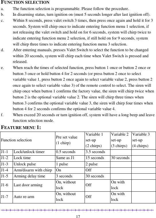
PORTMAN ELECTRONICS T53-915 CAR ALARM User Manual PORTMAN CAR ALARM FEATURES

PORTMAN ELECTRONICS (DONGGUAN) CO., LTD. CAR ALARM PORTMAN CAR ALARM FEATURES

User Manual

            PORTMAN SECURITY SYSTEMS, LTD TWO-WAY CAR ALARM   Operation/ Installation Manual    AM9600---T89/T53/RX04    10/20/2012 Version 1.1
                                                                                                              1      4T89(Two way)12376576T53(One way)      12354charge                                         T89                                   T53 (Two way)            (One way) Functions Conditions Press button 1 once Arm and lock doors Car finder with sound Stop alarm temporarily Remote lock doors Disarmed and Ignition OFF Armed Sounding  While driving Press and hold button 1 for 2 sec. Remote Panic Anytime Press button 2 once Disarm/unlock Stop alarm temporarily Remote unlock doors Armed Sounding While driving Press and hold button 2 for 2 sec. All door unlock/disarm Arming Press and hold button 3 for 2 sec. Open trunk (Channel 1 output) Anytime
                                                                                                              2 Press button 4 once then press button 1 within 3 sec. Active anti car hijacking  While driving   Channel 2 output  Anytime Press button 4 once then press button 3 within 3 sec. Channel 3 output  Anytime Press button 4 once then press button 4 within 3 sec. Channel 4 output  Anytime Press and hold button 4 for 2 sec. Remote start on/off When start procedure ready Press button 1 + 4 once together Arm with bypass shock sensor Disarming and ignition OFF Press button 3 + 4 once together Manual active ready mode Ignition on & disarming & handbrake on Press button 5 once then press button 1 within 3 sec. Silent arm Disarmed and ignition OFF Press button 5 once then press button 2 within 3 sec. Silent disarm Arming Press button 5 once then press button 3 within 3 sec. Silent arm with bypass ext. sensor  Disarmed and ignition OFF Press button 5 once then press button 4 within 3 sec. Timer start on/off When start procedure ready Press button 5 once then press button 5 within 3 sec. Valet mode on/off Disarming Press button 5 once then press and hold button 1 for 2 sec. within 3 sec.  No alarm arm mode Disarmed and ignition OFF Press button 1+3 for 2 seconds(Only T89) Transmitter power off Transmitter power on Note: press button 6 can control different main unit 。  Receiver RX04
                                                                                                              3   CANBUS FUNCTION 1. ARM IN +: This input wire is normally connected to the vehicle’s CANBUS interface. The system will enter arming mode when it detected arming signal from the CANBUS interface.  2. DISARM IN +: This input wire is normally connected to the vehicle’s CANBUS interface. The system will enter disarming mode when it detected disarming signal from the CANBUS interface.  3. Hood trigger -: This input wire is normally connected to the vehicle’s CANBUS interface. The system will alarm in arming mode when it detected hood trigger signal from the CANBUS interface.  4. Ignition input +: This input wire is normally connected to the vehicle’s CANBUS interface. If it detected ignition trigger signal from the CANBUS interface, then the system will alarm in arming mode, and the system will enter driving mode in disarming mode.  5. Door trigger -: This input wire is normally connected to the vehicle’s CANBUS interface. The system will alarm in arming mode when it detected door trigger signal from the CANBUS interface.  6. Trunk trigger -: This input wire is normally connected to the vehicle’s CANBUS interface. The system will alarm in arming mode when it detected trunk trigger signal from the CANBUS interface.
                                                                                                              4                  PC SETUP FUNCTION When unit is in disarming & Door open status, Select the correct COM port number, and then set the following functions
                                                                                                              5   Default: to use factory default setting Request: read out the setting in the current page. Apply: transfer the setting to unit in the current pages. Exit: exit PC-Setup program.  BASIC CAR ALARM FUNCTION DESCRIPTION CODE LEARNING a. When in disarmed mode. b. Turn ignition ON, press Valet Switch 10 times within 8 seconds, siren will chirp 3
                                                                                                              6 times, system will enter code-learning mode.  c. Press any button on the transmitter, the siren will chirp accordingly for confirmation as soon as the transmitter is learned. For example, if the first transmitter is learned, the siren will chirp once. If the second transmitter is learned, the siren will chirp twice, etc… d. Up to 3 transmitters can be programmed. e. If one of the transmitters is programmed, the other transmitters must be reprogrammed within 8 seconds. Turn ignition OFF or 8 seconds later, system will exit code- learning mode.  ARMING a. Press button 1. b. Siren will chirp once. Parking lights will flash once. c. Disables engine starter. d. The doors will be locked after 0.5 seconds or 3.5 seconds. (see function selection J1-1)  e. Two-way transmitter will chirp once. f. LED will flash slowly  g. After 3 seconds, all the sensors are armed. If the alarm shock sensor is triggered within 3 seconds, the siren will chirp twice and the circuit will be by-passed. Alarm will rearm by itself only when the sensor is stable for 2 seconds.   h. If doors, trunk, hood are not closed enter arm, siren will chirp 5 time.  ARMING WITH BYPASSING SHOCK SENSOR a. Press button 4 and button 1 together once  b. Siren will chirp once then long chirp once and parking light will flash once, the system is entry in armed mode, all sensors will be bypassed in this arming cycle.  SILENT ARMING a. In disarming state,press button 5 once then press button 1 once within 3 seconds. b. Parking light will flash once.  c. Disables engine starter. d. Door will be locked at 0.5seconds or 3.5 seconds (See Function Selection J1-1). e. After  3  seconds, all  the sensors  are  armed.  If  the  alarm  shock  sensor  is  triggered within 3 seconds, the siren will chirp twice and the circuit will be by-passed. Alarm will rearm by itself only when the sensor is stable for 2 seconds. f. LED will flash slowly.
                                                                                                              7  SILENT ARMING WITH BYPASSING SHOCK SENSOR a. In disarming state, press button 5 once then press button 3 once within 3 seconds.  b. Parking light will flash once, the system is entry in silent armed mode, all sensors will be bypassed in this arming cycle.  HIDDEN ALARM ARMING  a. First press button 5 then press and hold button 1 for 2 seconds within 3 seconds b. Siren will chirp twice and parking light will flash twice, the system will entry in no alarm arming mode. c. In this arming mode, the siren and parking light will not alarm if any sensor will be triggered, but the system will remain send trigger signal to the transmitter.  ALARM PERIOD AND SOUNDING CYCLE  a. While arming, if any detector is triggered, the siren will sound 30 seconds (max) and the parking light will flash 30 seconds (max).  b. For any single trigger, the siren will sound one cycle only. (One cycle is: sound 30 seconds and stop 3 seconds.) c. For the same arming period, and for each single detector, the system can only be triggered (single trigger) at most 8 times. d. For each individual detector, the number of sounding cycle can be accumulated in the same arming period.  (E.g. If open the door, and let the siren sound 5 cycles, and close the door, the siren will stop sound, then if open the door again, it can only sound 3 cycles.) e. After 8 cycles, the triggered detector will be bypassed. This detector will not be triggered again in the same arming period. f. The system is disarmed; the all the detector is return normal status.  TRANSMITTER DISPLAY REPORT WHEN SYSTEM TRIGGER a. The system is in arming status. b. If the shock sensor is warned triggered, piezo will continue sound. c. If the shock sensor or ext sensor is fully triggered, the unit will send the information to transmitter, piezo will continue sound. d. If the door is triggered, the unit will send the information to transmitter, piezo will continue sound. e. If ignition has been triggered, the unit will send the information to transmitter, piezo
                                                                                                              8 will sound continually. f. If the trunk is triggered, the unit will send the information to transmitter, piezo will continue sound. g. If the hood is triggered, the unit will send the information to transmitter, piezo will continue sound. h. The transmitter alarm display (icon flash and piezo sound) will continuously for 30 seconds (max), within 30 seconds, press button 1 or button 2 will stop alarm.  DISARMING  a. Press button 2.  b. Siren will chirp 3 times, parking lights will flash 3 times. If siren chirps 4 times and parking lights flash 4 times, which means the alarm has been triggered during arming state.  c. Press button 3 and button 2 together once the system will silent disarming, only parking light will flash indication. d. Doors will be unlocked after 0.5 seconds or 3.5 seconds (see function selection J1-1).  e. If somewhere was triggered, the LED will flash to indicate as following:  Quick flash 2 times after a pause           Shock sensor or ext sensor full trigger Quick flash 3 times after a pause           Door trigger Quick flash 4 times after a pause           Trunk trigger Quick flash 5 times after a pause           Hood trigger Quick flash 6 times after a pause           IGN trigger f. Dome light will be ON for 30 seconds (if selective dome light output), and will be OFF when ignition ON.   AUTOMATIC REARMING (SEE FUNCTION SELECTION J1-7) After disarm, the system will be re-armed automatically or re-arm with door lock after 30 seconds if the ignition does not turn ON or the door is not open.  LAST DOOR ARMING (SEE FUNCTION SELECTION J1-6) a. Turn ignition ON, then OFF and close the last door. After 30 seconds, the system will arm automatically or arm with door lock. b. If one of the doors is opened during the above mentioned 30 seconds periods, system will postpone enter arming mode till all doors are closed.
                                                                                                              9  SMART IMMOBILIZATION (SEE FUNCTION SELECTION J1-11) a. When ignition is turned to OFF for 2 min, if the alarm is not armed, the engine will be cut automatically and cannot be restarted. LED will be ON for 0.5 seconds and then OFF for 3 seconds, and circle. b. Exit auto-immobilization mode: when ignition OFF, press button 2 once, Or please perform OVERRIDE PROCEDURE.  2-STAGE SENSOR a. If car receives a light shock, siren will chirp five times and parking lights will flash once for warning purpose. b. If car receives a heavy signal, siren will sound and parking lights will flash for 30 seconds immediately.  DOOR LOCK CONTROL (WHILE DRIVING) a. Press button 1 to lock doors. The doors can be locked. b. Press button 2 to unlock doors. The doors can be unlocked.  AUTOMATIC DOOR LOCK (SEE FUNCTION SELECTION J1-8)  When the system is disarming and the ignition turn from OFF to ON, door will lock after 15 seconds or door will lock with footbrake is press first.   AUTOMATIC DOOR UNLOCK (SEE FUNCTION SELECTION J1-9) When the ignition turns from ON to OFF, doors will automatically unlock.  SECOND UNLOCK (SEE FUNCTION SELECTION J2-4) If  the  system is  selection  second  unlock  on,  press  and hold  button  2  for  2  seconds,  the second unlock will output 300mA negative signal.  OPEN TRUNK (CHANNEL 1 OUTPUT) (SEE FUNCTION SELECTION J2-3 /J2-8) a. Anytime, press and hold button 3 for 2 seconds will to open trunk (channel 1 output) (with 300mA negative output).
                                                                                                              10 b. If the system is in arming at this time, the trunk trigger, ext sensor is by-pass till the channel output off. After 4 seconds, the system is in arm mode again.  CHANNEL 2 OUTPUT (SEE FUNCTION SELECTION J2-4 /J2-11) a. Anytime, first press button 4 once then press button 2 once within 3 seconds will to remote channel 2 output (with 300mA negative output). b. If the system is in arming at this time, the trunk trigger, ext sensor is by-pass till the channel output off. After 4 seconds, the system is in arm mode again.  CHANNEL 3 OUTPUT (SEE FUNCTION SELECTION J2-5 /J2-12) a. Anytime, first press button 4 once then press button 3 once within 3 seconds will to remote channel 3output (with 300mA negative output). b. If the system is in arming at this time, the trunk trigger, ext sensor is by-pass till the channel output off. After 4 seconds, the system is in arm mode again.  CHANNEL 4 OUTPUT (SEE FUNCTION SELECTION J2-6 / J2-13) a. Anytime, first press button 4 once then press button 4 once within 3 seconds will to remote channel 4 output (with 300mA negative output). b. If the system is in arming at this time, the trunk trigger, ext sensor is by-pass till the channel output off. After 4 seconds, the system is in arm mode again.  PANIC MODE a. Anytime press and hold  button 1 for  2 seconds. The  siren  will sound and  parking lights will flash for 30 seconds b. Press button 1or 2 to stop the panic.  CAR FINDER a. The system is armed. b. Press button 1: siren will chirp 6 times, the parking lights will flash 12 times. At the same time, the door will lock. c. Press button 2 to stop car finder and disarm.   POWER ON MEMORY This security system is equipped with circuitry that will allow the unit to remember its
                                                                                                              11 alarm status if the power is lost and then reconnected.  VALET MODE a. The system is disarming, turn ignition ON, within 8 seconds press and hold valet switch 3 seconds or press button 5 twice within 3 seconds. b. LED will be constantly ON, the parking light will flash once. c. In VALET mode, siren will chirp once and parking lights will flash once when lock the door, and siren will chirp twice and parking lights will flash twice when unlock the door. d. In Valet mode, there is no arm and trigger alarm function, and it cannot enter smart immobilization and anti car jacking. e. Leave valet mode:  press button 5 twice within 3 seconds. f. LED will be OFF, and the parking light will flash twice which indicates that system exit valet mode.  ANTI CAR JACKING (SEE FUNCTION SELECTION J2-1, 2) The system provides 3 ways to enter anti-car jacking mode.   For MODE A, there are three ways to enter anti carjacking: a. When  ignition  ON,  first  press  transmitter  button  4  once  then  press  button  1  once within 3 seconds to activate the anti carjacking. b. When ignition ON, after the door is opened, the system will enter anti carjacking. Within 10 seconds, pressing button 1 once of the transmitter will bypass the action of opening the door, and the system will exit anti carjacking mode. And the parking will flash once and siren will chirp once. Or perform Emergency disarming to exit the anti car jacking mode, that is to say, Within 71 seconds press and hold valet switch once for one second to exit anti jacking mode. c. After  turning  ignition  ON,  the  system  will  enter  anti  carjacking  mode  at  once. Within 10 seconds, pressing button 1 once of the transmitter will bypass the action of  turning  ignition  ON,  and  the  system  will  exit  anti  carjacking  mode.  And  the parking  will  flash  once  and  siren  will  chirp  once.  Or  perform  Emergency disarming to exit the anti car jacking mode, that is to say, Within 71 seconds press and hold valet switch once for one second to exit anti jacking mode. For MODE B, there are two ways to enter anti carjacking: The above b and a ways are available for mode B.
                                                                                                              12 For MODE C, there is one way to enter anti carjacking: The above a way is available for mode C.  WHEN THE SYSTEM ENTERS ANTI CARJACKING MODE a. From the beginning to 15 seconds, nothing happen. b. From 16 to 30 seconds, the LED will blink slowly. c. From 31 to 45 seconds, the LED will blink fast and the siren will chirp once per 2 seconds.  d. Form 46 to 70 seconds, the LED will blink fast and the siren will chirp once per seconds. e. After 71 seconds, the siren will sound and the parking light will flash continuously. The arming wire will output negative 300mA current.  f. After turn ignition OFF, the siren will sound and the parking lights will flash for 3 minutes before they stop.  g. Turn ignition ON again without exiting anti carjacking mode, the siren will sound and the parking lights will flash continuously again. TO EXIT: perform Emergency disarming to exit the antijacking  Note: when system entered anti car jacking, the transmitter cannot control the unit.  Emergency disarming (See Function Selection J1-13) Please refer to its instruction for emergency disarm the system as following:  1. SIMPLE WAY: Please turn ignition ON, press and hold valet switch once for 1 second. Siren will chirp 4 times and  the parking lights will  flash 4 times, which indicates that the system is disarmed.   2. 2ND WAY:  Please refer 2-pin code override procedure:  2-PIN CODE OVERRIDE PROCEDURE:  a. Turn ignition ON, press valet switch 5 times within 8 seconds. b. After 8  seconds, the LED should stay ON  solid for 5 seconds, after the 5  seconds LED begins to flash.
                                                                                                              13 c. When the LED flashes the 1st number of the 2-pin code, turn ignition OFF. Then turn back ON to wait for LED to flash the 2nd number of the 2-pin code. When the LED  flashes  the2nd  number of  the 2-pin  code,  turn ignition  OFF  When  complete, siren will sound 4 times and the parking lights will flash 4 times to indicate system override, which indicates that the system is disarmed. d. If LED flashes over 12 times, it means the program exits override procedure.  e. If failed the override procedure, will need to turn off the ignition and return to step a.    PROGRAM PERSONAL 2 PIN CODE (FACTORY DEFAULT SETTING 1,2) Pin code program procedure: (system disarmed) a. Turn ignition ON, press valet switch 5 times within 8 seconds.  b. After 8seconds,  the  LED  should  stay ON  solid  for  5 seconds,  after the  5  seconds LED begins to flash. c. To change the factory pin code setting.  Turn ignition OFF after the LED flashes the 1st pin code.  Then turn ignition back ON to wait for LED to flash the 2nd pin code. When the LED flashes the2nd number of the 2-pin code, Turn ignition OFF, If the pin code recognition failed, the system will exit pin code setting automatically.  d. Then turn ignition ON, and set the pin code as the LED flashes your selected 1st pin, then turn ignition OFF.  Siren will sound with number of times to indicate new pin code for the system. Follow the same method for the 2nd pin code.  The new 2-pin code will be recorded in EEPRON IC when completed.  NOTE: If the 2nd pin code setting is incorrect then the system will default pin code setting. The PIN code should within 1~9, 0 is not acceptable, wrongly input will exit the mode.   REMOTE ENGINE START FUNCTION DESCRIPTION RPM LEARNING (SEE FUNCTION SELECTION J3-4) a. When the system is disarming and ignition ON, press valet switch 6 times within 10 seconds, the parking lights will flash twice to indicate that system has entered the RPM learning mode. b. Start the engine, when the RPM level is stabilized, press and hold valet switch till the parking lights will flash twice and the siren will chirp twice, which indicates the RPM value has been memorized successfully.
                                                                                                              14 NOTE: The unit remote start defaults check mode is Voltage mode; before the system entry the RPM learning mode, user must connect the vehicle RPM wire to the unit and function selection must select the start check mode is RPM mode.   TURBO MODE (SEE FUNCTION SELECTION J3-11) a. The turbo mode is used for protect the engine. b. Before the ignition is turned from ON to OFF (ignition must be ON more than 10 seconds), the engine will not shutdown immediately, but continue remain running for 3 minutes. c. The engine will stop running immediately if step foot brake or release hand brake.  Reservation procedure for manual gear car (See Function Selection J3-1, J3-2) a. If the car is the manual gear car, the unit must to perform the reservation procedure before the remote engine start, the reservation procedure has two setting mode selection. b. The manual setting mode operation is following: c. When the engine running, before you turn ignition OFF to stop the engine, pulls up the hand brake, release the foot brake. d. Gear keeps in Empty position. e. Press button 3+4 once together. f. Turn ignition OFF, the engine will still remain running for 2 minutes. Within 2 minutes, open and close the door, the parking light will flash twice indicate that the reservation procedure is successful. g. In auto pre-set setting mode, when the engine running, Engine will automatically running 2 minutes after ignition off as reservation. Within 2 minutes, open and close the door, the parking light will flash twice indicate that the reservation procedure is successful. h. If reservation produce is failed, or within 2 minutes no any action, the parking light will flash four times indication, then you must perform the step again. i. Turn ignition ON, or open the hood, or press the foot brake, or pull down the hand brake will cause the unit to exit the reservation mode.
                                                                                                              15 REMOTE START OPERATION Remote start activation: The following inputs will activate the Remote Start sequence and if a successful start enters the ‘RUN’ mode. Transmitter activation: the transmitter button 4 is press and hold 2 seconds when the ignition is OFF.  REMOTE START ‘RUN’ MODE: The ‘RUN’ mode begins when the unit has recognized a successful start.  a. RUN time: The unit will keep the engine running for a maximum of 10 minutes (5, 20,30min option) from the time of a successful start. the unit will exit the ‘RUN’ mode less than 10 minutes (5, 20,30min option) from the time of a successful start ONLY by Remote start de-activation input.  EXIT REMOTE START: The following inputs & operations will cause the unit to exit the ‘RUN’ mode and will not attempt to start again until the unit receives a remote start activation input. (if reservation procedure is successful, then if user: 1 pull down the handbrake; 2 press the foot brake; 3 open the hood, the reservation procedure will canceled when remote start.) a. Transmitter de-activation: the Transmitter button 4 is press and hold 2 seconds of each other b. The unit has reached the end of the 10 minute ‘RUN’ time (5, 20,30min option). c. The unit detects a RPM signal at 8 times the programmed value (if RPM detect mode). d. Voltage input: in voltage mode the unit detects the voltage is drop 1.0V for more than 5 consecutively seconds during ‘RUN’ time (if voltage detect mode). e. Unsuccessful start attempts: Three consecutively unsuccessful start attempts.   TIMER START MODE OPERATION a. Timer mode activation: Anytime, press button 5 once then press button 4 once within 3 seconds. b. The parking lights will flash 4 times as confirmation of activating ‘Timer mode’. c. Timer mode start interval: The operator has the option to have the unit start every 12 or 1or 3 or 6 hours. Factory default is 12 Hour intervals. To select 12 or 1or 3 or 6
                                                                                                              16 hour automatic start timer in feature programmable. d. When timer modes start successful.NOTE1: This feature cannot be activated when the ignition is ON or the unit is in the ‘RUN’ mode. NOTE2: 3 Unsuccessful starts attempts will count as 1 successful start. The unit will attempt to start again at the next Timer mode start interval.   EXIT TIMER MODE: The following inputs & operations will cause the unit to exit the ‘TIMER’ mode. a. press button 5 once then press button 4 once within 3 seconds. b. (+) Input on the foot brake input wire c. (-) Input on the hand brake input wire d. (-) Input on the hood pin wire e. The ignition is ON while the unit is NOT in the ‘RUN’ mode. f. The unit has called the Remote Start activation option additional times.  g. ‘RUN’ mode is exited due to RPM signal 8 times programmed value (if RPM detect mode).  DIAGNOSTICS MODE When the engine stop running. Than the parking light will flash “N” times indicate the reason for shutdown. The indications are as follows:     1Flash      10(5, 20, 30) min run timer expired or transmitter activation input.     2Flashes     Low or No RPM signal received.     3Flashes     hand brake input shut down.     4Flashes     foot brake or open hood input shut down.     5Flashes     High RPM signal over speed shut down     6Flashes     RPM has not learned.     7Flashes     voltage not raised or voltage has drop     8Flashes     manual gear car not perform the reservation procedure  RETURN TO FUNCTION FACTORY DEFAULT SETTING a. In disarming status, turn Ignition OFF to ON 4 times, and ignition will stay in on position. b. Press valet switch 12 times then press once again and hold it until 6 chirps with a long chirp is hearing then release the valet switch. c. The all-programmable feature returns to factory default setting.
                                                                                                              17  FUNCTION SELECTION a. The function selection is programmable. Please follow the procedure.  b. In disarming status, turn ignition on (must 5 seconds longer after last ignition off). c. Within 8 seconds, press valet switch 3 times, then press once again and hold it for 3 seconds. System will chirp once to indicate entering function menu 1 selection, if not releasing the valet switch and hold on for 6 seconds, system will chirp twice to indicate entering function menu 2 selection, if still hold on for 9 seconds, system will chirp three times to indicate entering function menu 3 selection. d. After entering manuals, presses Valet Switch to select the function to be changed within 20 seconds, system will chirp each time when Valet Switch is pressed and released. e. When reach the times of selected function, press button 1 once or button 2 once or button 3 once or hold button 4 for 2 seconds (or press button 2 once to select variable value 1, press button 2 once again to select variable value 2, press button 2 once again to select variable value 3) of the remote control to select. The siren will chirp once when button 1 confirms the factory value, the siren will chirp twice when button 2 is the optional variable value 2. The siren will chirp three times when button 3 confirms the optional variable value 3, the siren will chirp four times when button 4 for 2 seconds confirms the optional variable value 4. f. When exceed 20 seconds or turn ignition off, system will have a long beep and leave function selection mode. FEATURE MENU 1:  Function selection Pre set value (1 chirp) Variable 1 set-up  (2 chirps) Variable 2 set-up  (3 chirps) Variable 3 set-up  (4 chirps) J1-1 Lock/unlock timer 0.5 seconds 3.5 seconds   J1-2 Lock time Same as J1 15 seconds 30 seconds  J1-3 Unlock pulse 1 pulse 2 pulse   J1-4 Arm/disarm with chirp On  Off   J1-5 Arming delay time 3 seconds 30 seconds   J1-6 Last door arming On, without lock Off On with lock  J1-7 Auto re-arm On, without lock  Off On with lock
                                                                                                              18 J1-8 Automatic door lock On Off Lock with footbrake  J1-9 Automatic door unlock On Off   J1-10 Alarm period 8 cycles No limit   J1-11 Smart immobilized On  Off   J1-12 Siren alarm duration 30 seconds 60 seconds   J1-13 Emergency override way Simple way 2 pin code way   J1-14 Default setting On     FEATURE MENU 2: Function selection Pre set value (1 chirp) Variable 1 set-up (2 chirps) Variable 2 set-up  (3 chirps) Variable 3 set-up (4 chirps) J2-1 Anti car jacking function Off On   J2-2 Anti car jacking mode Mode C Mode B Mode A  J2-3 Programmable L1 output Trunk (Channel 1) output CH1 output and disarm Output pulse after start Output pulse during crank J2-4 Programmable L2 output Channel 2 output Second unlock output CH2 output and disarm Output pulse before start J2-5 Programmable L3 output Channel 3 output Horn output CH3 output and disarm Output pulse after shutdown J2-6 Programmable L4 output Dome light output Channel 4 output CH4 output and disarm Remote start status output J2-8 Trunk (Channel 1) output Momentary output  Latched output  Latched output and reset with ignition 30 seconds timed
                                                                                                              19 ON J2-9 Horn timing 10ms 50ms 20ms 30ms J2-10 Ignition control dome light On Off   J2-11 Channel 2 output Momentary output  Latched output  Latched output and reset with ignition ON 30 seconds timed J2-12 Channel 3 output Momentary output  Latched output  Latched output and reset with ignition ON 30 seconds timed J2-13 Channel 4 output Momentary output  Latched output  Latched output and reset with ignition ON 30 seconds timed J2-14 Default setting On     FEATURE MENU 3: Function selection Pre set value (1 chirp) Variable 1 set-up (2 chirps) Variable 2 set-up (3 chirps) Variable 3 set-up (4 chirps) J3-1 Vehicle model Automatic gear Manual gear   J3-2 Manual gear reservation setting Manual set Auto pre-set   J3-3 Engine checking on/off Engine checking on Engine checking off   J3-4 Check mode when start Voltage checking type Tachometer checking type   J3-5 High/low voltage check High voltage Low voltage
                                                                                                              20 level check level  check level  J3-6 Cranking time  1.0s 0.6s 0.8s 2.0s J3-7 Gasoline/Diesel Gasoline 2s warn-up timer Diesel 15s warn-up timer Diesel 30s warn-up timer Diesel 45s warn-up timer J3-8 Remote timer start 12H 1H  3H 6H J3-9 Warm-up duration 10 MIN 5MIN 20MIN 30MIN J3-10 Parking light output during running Flash Steady on   J3-11 Turbo mode Off On   J3-12 External module type Idata Fortin GP300  J3-13 Crank time mode of tachometer checking type 4 Cycle tachometer sensing Smart tachometer sensing 2 Cycle tachometer sensing  J3-14 Default setting On      FEATURE MENU 1 EXPLANATION: J1-1. LOCK/UNLOCK TIMER Pre-set: After press arm/disarm, the door is locked/unlocked output 0.5 seconds. Variable1: After press arm/disarm, the door is locked/unlocked output 3.5 seconds.  J1-2. LOCK TIMER Pre-set: same as J1. Variable 1: After press arm the door is locked output 15 seconds. Variable 2: After press arm the door is locked output 30 seconds.  J1-3. UNLOCK PULSE Pre-set: After presses disarm the door is unlocked output one pulse. Variable 1: After presses disarm the door is unlocked output two pulse.
                                                                                                              21  J1-4. ARM/DISARM WITH CHIRP Pre-set: Arm/Disarm will have chirp indication.  Variable 1: Arm/Disarm will not have chirp indication.  J1-5. ARMING DELAY TIME Pre-set: delay 3s.  Variable 1: delay 30s.   J1-6. LAST DOOR ARMING Pre-set: Turn ignition ON to OFF and close the last door. After 30seconds, the system will arm itself without lock.  Variable1: Delete this feature. Variable2: Turn ignition ON to OFF and close the last door. After 30seconds, the system will arm itself with lock.  J1-7. AUTO RE-ARM  Pre-set: The system is disarming without ignition ON or open the door. After 30seconds, the system will arm itself without lock.  Variable1: Delete this feature. Variable2: The system is disarming without ignition ON or open the door. After 30seconds, the system will arm itself with lock.  J1-8.AUTOMATIC DOOR LOCK Pre-set: When the ignition turns from OFF to ON, doors will lock after 15 seconds. Variable1: When the ignition turns from OFF to ON, door will not lock. Variable2: When the ignition turns from OFF to ON, door will lock with press the footbrake first.
                                                                                                              22  J1-9.AUTOMATIC DOOR UNLOCK Pre-set: When the ignition turns from ON to OFF, doors will unlock immediately. Variable1: When the ignition turns from ON to OFF, door will not unlock.  J1-10.ALARM PERIOD Pre-set: the system can only be triggered at most 8 times. Variable1: the system’s triggered times is no limited.  J1-11.SMART IMMOBILIZE Pre-set: this feature exists. Variable 1: Delete this feature  J1-12. SIREN ALARM DURATION TIME  Pre-set: the system is triggered; the siren and parking light will alarm 30 seconds.   Variable 1: the system is triggered; the siren and parking light will alarm 60 seconds.  J1-13. EMERGENCY OVERRIDE WAY  Pre-set: simple way.    Variable 1: 2 pin code way  J1-14. DEFAULT SETTING Pre-set: Return the feature menu 1 to the factory set-up.  FEATURE MENU 2 EXPLANATION: J2-1. ANTI CAR-HIJACKING Pre-set: Delete anti car-hijacking feature. Variable 1: Follow procedure to enter anti car-hijacking mode.
                                                                                                              23  J2-2. ANTI CAR-HIJACKING MODE SELECT Pre-set: entry anti car-hijacking way is mode C. Variable 1: entry anti car-hijacking way is mode B. Variable 2: entry anti car-hijacking way is mode A.  J2-3.PROGRAMABLE L1 OUTPUT SELECT Pre-set: Trunk (channel 1) output. Variable1: Trunk (channel 1) output and disarming Variable2: output pulse after start. The wire will provide a 1 seconds -300mA pulsed ground output after the vehicle is started under control of the remote start unit. Typically this wire will be used to re-lock the vehicle doors if the doors unlock automatically when the factory anti-theft system is disarmed. Variable 3: output pulse during crank. The wire will provide a -300mA ground output while the starter output of the remote start unit is active. This output can be used to activate the Crank Low/Bulb Test wire found in some GM vehicles. This wire is also referred to as the ECM wake up wire in some Chrysler vehicles.  J2-4. PROGRAMMABLE L2 OUTPUT SELECT Pre-set: channel 2 output. Variable1: seconds unlock output. Variable2: channel 2 output and disarming Variable 3: output pulse before start. The wire will provide a 1 seconds -300mA pulsed ground output 1.5 seconds before the remote start unit activates as well as when the transmitter is used to unlock the system to prevent false triggering of the factory alarm when the remote start unit engages or when the system is used to unlock the doors.  J2-5. PROGRAMMABLE L3 OUTPUT SELECT Pre-set: channel 3 output. Variable1: horn output. Note: horn output honk time is by J2-9 feature selection. Alarm output is on 10ms, off 200ms. Variable2: channel 3 output and disarming
                                                                                                              24 Variable 3: output pulse after shutdown. The wire will provide a 1 seconds -300mA pulsed ground output after the remote start unit shuts down. This output will occur regardless of whether the circuit times out or is manually terminated. Typically this output will be used to re-lock/re-arm the vehicle if the doors unlock automatically when the ignition circuit transitions to off or the factory anti-theft system is disarmed.  J2-6. PROGRAMMABLE L4 OUTPUT SELECT Pre-set: dome light output: when the system is alarming, the dome light ON as parking light. When disarm, dome light will ON until ignition ON (max 30 seconds). Variable1: channel 4 output.  Variable2: channel 4 output and disarm Variable 3: status continuant output when remote start.  J2-8. TRUNK (CHANNEL 1) OUTPUT MODE SELECT Pre-set: Momentary output: Anytime, press button 3 for 2sec. the CH1 will output-300mA constantly. Until the button 3 of transmitter are released. Variable1: Latched output: this selection will output a –300mA signal from the channel 1 output  as  soon  as  the  channel  1  button  is  pressed  and  will  continue  until  the  button  is pressed again. Variable2: Latched output/reset with ignition ON: this selection will output a –300mA signal from the channel 1 output as soon as the channel 1 button is pressed but will reset or stop when the ignition is turned ON. Variable3: 30 seconds output: this selection will continue output a 30 seconds –300mA signal from the channel 1 output as soon as the channel 1 button is pressed.  J2-9.HORN TIMING SETTING Pre-set: If  setting horn  output, when the  system is  arm/disarm with horn  honk, the  horn honk default timing is 10ms. Variable1: the horn honk timing is 50ms. Variable2: the horn honk timing is 20ms. Variable3: the horn honk timing is 30ms.
                                                                                                              25  J2-10. IGNITION CONTROL DOME LIGHT Pre-set: the dome light will off when ignition turn from off to on position, the dome light will illume (max: 30s) when ignition turn from on to off position. Variable 1: the dome light will not illume when ignition turn from on to off position.  J2-11. CHANNEL 2 OUTPUT MODE SELECT Pre-set: Momentary output: Anytime, within 3 seconds press button 4 once then press button 2 once, CH2 will output-300 mA. Variable1: Latched output: this selection will output a –300mA signal from the channel 2 output  as  soon  as  the  channel  2  button  is  pressed  and  will  continue  until  the  button  is pressed again. Variable2: Latched output/reset with ignition ON: this selection will output a –300mA signal from the channel 2 output as soon as the channel 2 button is pressed but will reset or stop when the ignition is turned ON. Variable3: 30 seconds output: this selection will continue output a 30 seconds –300mA signal from the channel 2 output as soon as the channel 2 button is pressed.  J2-12. CHANNEL 3 OUTPUT MODE SELECT Pre-set:  Momentary  output:  Anytime,  within  3  seconds  press  button  4  once  then  press button 3 once, CH3 will output-300 mA Variable1: Latched output: this selection will output a –300mA signal from the channel 3 output  as  soon  as  the  channel  3  button  is  pressed  and  will  continue  until  the  button  is pressed again. Variable2: Latched output/reset with ignition ON: this selection will output a –300mA signal from the channel 3 output as soon as the channel 3 button is pressed but will reset or stop when the ignition is turned ON. Variable3: 30 seconds output: this selection will continue output a 30 seconds –300mA signal from the channel 3 output as soon as the channel 3 button is pressed.
                                                                                                              26  J2-13.CHANNEL 4-OUTPUT MODE SELECT Pre-set:  Momentary  output:  Anytime,  within  3  seconds  press  button  4  once  then  press button 4, CH4 will output -300 Ma. Variable1: Latched output: this selection will output a –300mA signal from the channel 4 output  as  soon  as  the  channel  4  button  is  pressed  and  will  continue  until  the  button  is pressed again. Variable2: Latched output/reset with ignition ON: this selection will output a –300mA signal from the channel 4 output as soon as the channel 4 button is pressed but will reset or stop when the ignition is turned ON. Variable3: 30 seconds output: this selection will continue output a 30 seconds –300mA signal from the channel 4 output as soon as the channel 4 button is pressed.  J2-14. DEFAULT SETTING Pre-set: Return the feature menu 2 to the factory set-up.   FEATURE MENU 3 EXPLANATION: J3-1. VEHICLE MODE Pre-set: Automatic gear car: Without ‘ready mode’, remote start directly Variable1: Manual gear car: The ‘ready mode’ routine has been completed successfully system can remote start  J3-2. MANUAL GEAR CAR RESERVATION SETTING MODE Pre-set: Manual setting: When the engine running, press button 3+4 once to routine ‘ready mode’  Variable1: Auto pre-set setting: When the engine running exceed 10 seconds, ignition OFF will automatically routine ‘ready mode’
                                                                                                              27  J3-3. ENGINE CHECK SELECTION WHEN REMOTE START Pre-set: Engine check ON: remote start successfully, to detect voltage rise or RPM signal. (if voltage rise or RPM signal is interrupted suddenly, the unit will start two times). Variable 1: Engine check OFF: remote start successfully, to detect voltage rise or RPM signal. (if voltage rise or RPM signal is interrupted suddenly, the unit will not start).  J3-4. CHECK MODE WHEN START Pre-set: Voltage checking type. Variable 1: RPM checking type.  J3-5. VOLTAGE CHECK LEVEL Pre-set: High voltage checks level.  Variable 1: Low voltage checks level.  J3-6. CRANK TIME SELECTION Pre-set: 1 second.  Variable1: 0.6 seconds.  Variable2: 0.8 second. Variable3: 2 seconds.  J3-7. GASOLINE ENGINE/DIESEL ENGINE Pre-set: Gasoline engine without wait-to-start light 2 seconds warm-up timer. Variable1: Diesel engine without wait-to-start light 15 seconds warm-up timer. Variable2: Diesel engine without wait-to-start light 30 seconds warm -up timer. Variable3: Diesel engine without wait-to-start light 45 seconds warm -up timer.  J3-8. TIMER REMOTE START  Pre-set: interval time is 12 hours in timer remote start.  Variable1: interval time is 1 hour in timer remote start. Variable2: interval time is 3 hours in timer remote start.  Variable3: interval time is 6 hours in timer remote start.
                                                                                                              28  J3-9.REMOTE START WARM-UP DURATION Pre-set: 10 minutes. Variable1: 5 minutes. Variable2: 20 minutes. Variable3: 30 minutes.  J3-10.PARKING LING OUTPUT DURING RUNNING MODE Pre-set: keeping flash during running mode. Variable1: keeping steady on during running mode.  J3-11. TURBO MODE Pre-set: Turbo mode selection off. Variable 1: Turbo mode selection on.  J3-12. EXTERNAL MODULE TYPE Pre-set: I data link mode Variable 1: Fortin mode; Variable 2: GP300  J3-13. CRANK TIME MODE OF TACHOMETER CHECKING TYPE Pre-set: the engine remote start detect tachometer signal is 4-cycle pulse of tachometer.  Variable 1: the engine remote start detect tachometer signal is alterable by tachometer pulse frequency. Variable 2: the engine remote start detect tachometer signal is 2-cycle pulse of tachometer.  J3-14. DEFAULT SETTING Pre-set: Return the feature menu 3 to the factory set-up.  PHYSICAL PARAMETERS Enclosure dimensions 122*77*22mm Weight 120g
                                                                                                              29  ELECTRICAL DC Supply voltage  12V DC Tolerance voltage  9V~16V Current (With RF) <17mA Current (Without RF) <10mA  RF PARAMETERS – T53/T89 Frequency 915mHz Battery life Half a year TX range (with RX04) 1000Meter Static current <10uA  NOTE:    This device complies with Part 15 of the FCC Rules. Operation is subject to the following two conditions: (1) this device may not cause harmful interference, and (2) this device must accept any interference received, including interference that may cause undesired operation.
                                                                                                              30 x1000RPMGNDFUSE BOX  30AFUSE RED +12VRED +12V 30AFUSE      12VBATTERYPURPLE (START)BROWN IGN2ORANGE ACCYELLOW IGN1ONSTARTACCOFFSTART MOTOR RELAY3087a8586GREY/YELLOW DISARM IN +BROWN TG-BROWN/YELLOW HOOD -GREY/WHITE ARM IN +YELLOW IGNBROWN/WHITE TRUNK TRIGGER-WHITE/PURPLE CH3 OUTPUT -300mA+12VWHITE TG +PURPLE/BLACK DISARM OUTPUT -300m AFOOT BRAKE+12VBLACK/WHITE BRAKE10A FUSEORANGE -- LAMP INPUTORANGE -- LAMP OUTPUTBLACK -- GNDPURPLE/BLACK -- RPMWHITE/RED -- SIREN OUTPUTGRAY ARMEPURPLE CH1 / TRUNK OUTPUT -300mABLUE DOME LIGHTS OUTPUT -300mAHANDBRAKEGREEN HANDBRAKECANBUS PORTT89 RECEIVER OR OPTIONAL PC SETUP CABLEVALET SWITCHLEDSK600OPTIONAL SHOCK SENSORBLUE/WHITE (-) LOCK OUTPUT -300m AGREEN/WHITE (-) UNLOCK OUTPUT -3 00mAANTGNDFUSE BOX      12VBATTERYRED -- +12VYELLOW/GREEN IGN3 OUTPUT -300mAWHITE/ORANGE CH2 OUTPUT -300mA5A FUSEBROWN/WHITE TRUNK TRIGGER -GREY/WHITE ARM IN +YELLOW IGNITION INPUT +BROWN DOOR TRIGGER -BORWN/YELLOW HOOD TRIGGER -GREY/YELLOW DISARM IN +IDATA UPGRADE PORTLAMP1N54011N5401TM300OPTIONALTEMPERATURE SENSORT89 RECEIVEROPTIONALPC SETUP CABLERX04
                                                                                                              31 STATEMENT  changes or modifications not expressly approved by the party responsible for compliance could void the user’s authority to operate the equipment.  This device complies with Part 15 of the FCC Rules. Operation is subject to the following two conditions: (1) this device may not cause harmful interference, and (2) this device must accept any interference received, including interference that may cause undesired operation.  This equipment has been tested and found to comply with the limits for a Class B digital device, pursuant to Part 15 of the FCC Rules. These limits are designed to provide reasonable protection against harmful interference in a residential installation. This equipment generates, uses and can radiate radio frequency energy and, if not installed and used in accordance with the instructions, may cause harmful interference to radio communications. However, there is no guarantee that interference will not occur in a particular installation. If this equipment does cause harmful interference to radio or television reception, which can be determined by turning the equipment off and on, the user is encouraged to try to correct the interference by one or more of the following measures: -- Reorient or relocate the receiving antenna. -- Increase the separation between the equipment and receiver. -- Connect the equipment into an outlet on a circuit different from that to which the receiver is connected. -- Consult the dealer or an experienced radio/TV technician for help.  This device complies with Industry Canada license-exempt RSS standard(s). Operation is subject to the following two conditions: (1) this device may not cause interference, and (2) this device must accept any interference, including interference that may cause undesired operation of the device. Le présent appareil est conforme aux CNR d'Industrie Canada applicables aux appareils radio  exempts de licence. L'exploitation est autorisée aux deux conditions suivantes : (1) l'appareil ne  doit pas produire de brouillage, et (2) l'utilisateur de l'appareil doit accepter tout brouillage  radioélectrique subi, même si le brouillage est susceptible d'en compromettre le fonctionnement.

Navigation menu