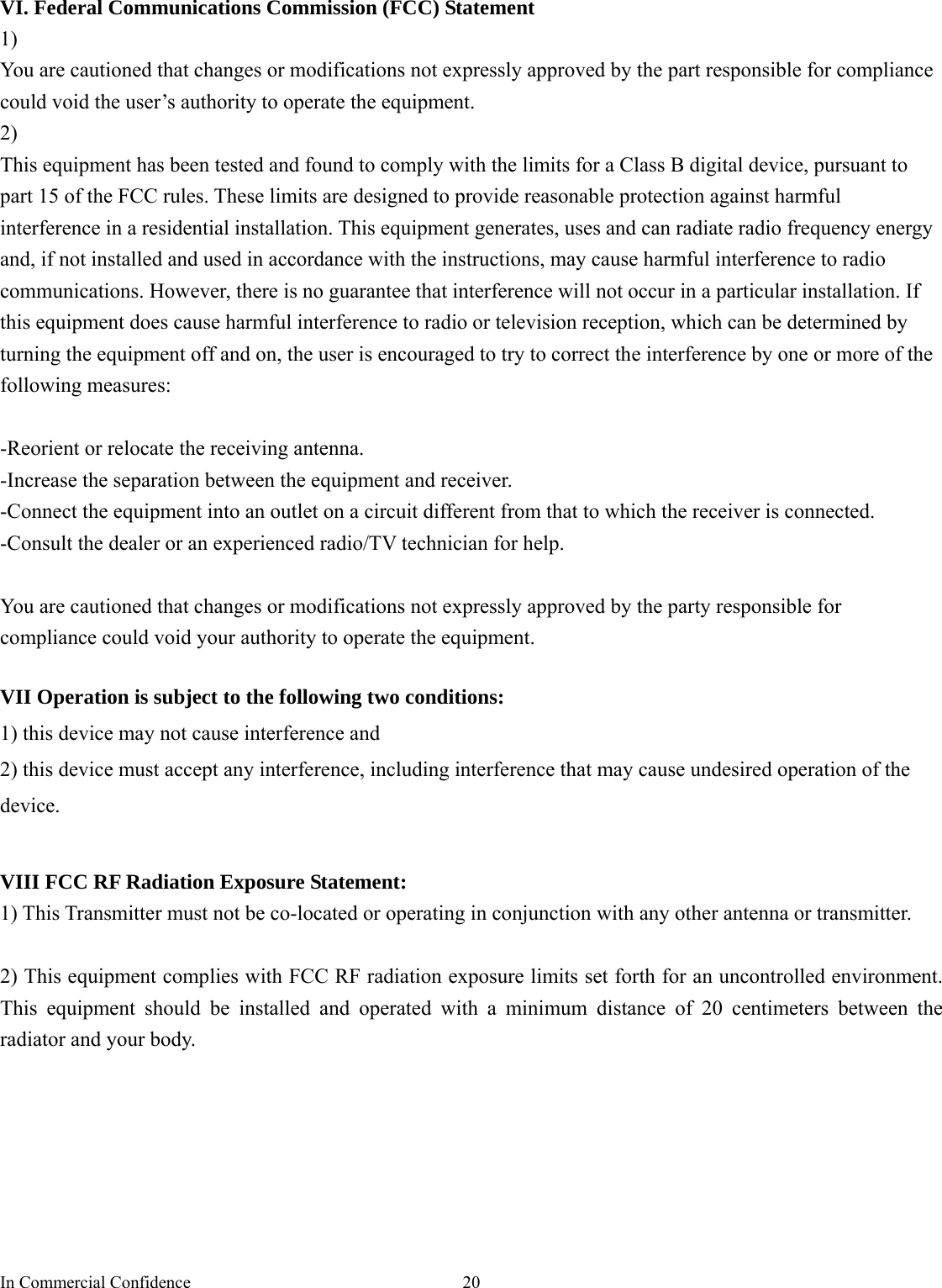
PORTMAN ELECTRONICS TLU-100N TRAILER TRACKING SYSTEM User Manual
PORTMAN ELECTRONICS (DONGGUAN) CO., LTD. TRAILER TRACKING SYSTEM
UserManual.wiki
>
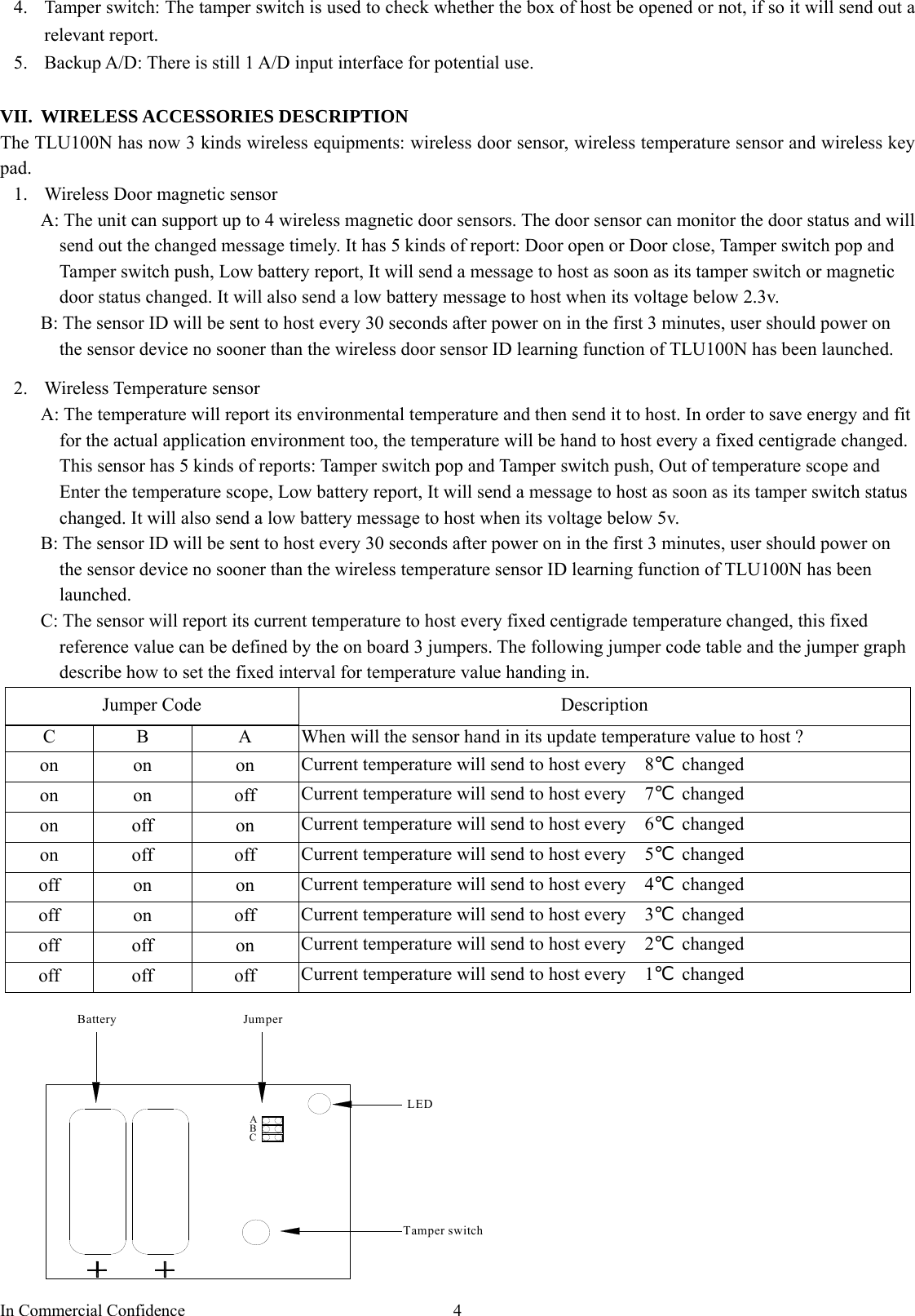
PORTMAN ELECTRONICS
>
TLU 100N User Manual
USERS MANUAL
Navigation menu
Upload a User Manual
Namespaces
Wiki Guide
HTML
PDF
Info
Views
User Manual
Discussion / Help
Navigation

![In Commercial Confidence 7C. MAIN INTERFACE The following is the brief Button Description for main interface: (1) Initialize: clear all saved parameters in TLU100N. (2) Request All: request all parameters that is saved previously in TLU100N (3) Request: request parameters in the current page (4) Apply: set the parameters in the current page (5) Apply All: save all the parameters into TLU100N (6) Load: load the saved configuration file (*.ptm) (7) Save: save the parameters into a files (*.ptm). (8) Exit: exit the PC-Setup program; the system will exit the PC setup mode and enter the working mode. 1. [User detail]: (1) Set Device ID for TLU100N. The TLU100N ID should be 4 to 8 decimal digitals characters. And the device ID must be unique in order to be identified by the server. (2) Set Access Point Name (APN), User Name (GPRS), Password (GPRS). Note that: The maximum length of the APN, User name and Password is 49 characters. Some service provider does not require USER name or PASSWORD, hence, user can leave blank in this section. (3) “TCP/UDP” address and Port number of alarm center being set, TLU100N will send message to the IP address. Note that: Only one TCP or UDP server will be used at a time. (4) SMS communication number setting: The primary SMS number is the default number, e.g.: when a important event can not send to user by internet then the report will send to user by this default number. The max SMS number is a limit for allowed out SMS. And the renew date is be used as a judge when shall the unit clear all SMS stored in it. (5) TLU100N can save 900 reports (899-0) recently; Click ‘Export’ button can export them into Excel or Notepad.](https://usermanual.wiki/PORTMAN-ELECTRONICS/TLU-100N/User-Guide-883621-Page-8.png)
![In Commercial Confidence 82.[Geofence]: 1) Circle Geofence setting: Set circular Geofence parameters in left window. The data should be coordinate center of the Geofence and the related radius. 2) Point Geofence setting: Set point Geofence in right part of the window, only GPS coordinate point data is needed. 3) Self-Geofence setting: Self-Geofence is a fresh idea for vehicle guard. User need only input a circle radius in this field. After this the unit will record that GPS position at the time the self-Geofence function be activated, from then on the unit will continuously check it new position and judge whether it is beyond the defined circle, if yes then send out an alert to user. This function is useful for an uncertain Geofence. The self-Geofence can be activated/deactivated by keypad *2*# or *3*# command after Duty-On command is entered. 3. [Report]:](https://usermanual.wiki/PORTMAN-ELECTRONICS/TLU-100N/User-Guide-883621-Page-9.png)
![In Commercial Confidence 9 In normal working mode (DUTY ON), the system will use the configurations as defined in this section. To activate the automatic report, please select “√” in checkbox and fill in data in the textbox. The reports will be summarized as (1) Intelligent report Parameters: On/Off, Report time when moving, Report time when stop, and threshold speed. Report when speed less than a preset value (refer the following 1.5 Km/Hr), and it will send stop report after a preset time (refer the following 120Sec). (min. speed is 0.1 km/Hr, max. speed is 1000 km/Hr). (2) Intelligent history report (record the report in the system’s flash ram) Parameters: On/Off, Report time when moving, Report time when stop, and Moving distance. (min. distance is 0.1 km, max. distance is 1000 km).Note that: these report will not be sent out but only be saved in flash memory. (3) AD detect report (AD1) [on/off] SEND REPORT IF ADC1 LESS THAN [min voltage] V for [debounce time] SEC, RESEND PER [resend time] SEC [on/off] SEND REPORT IF ADC1 MORE THAN [max voltage] V for [debounce time] SEC, RESEND PER [resend time] SEC [on/off] SEND REPORT IF ADC1 GO UP [up voltage] V for [debounce time] SEC](https://usermanual.wiki/PORTMAN-ELECTRONICS/TLU-100N/User-Guide-883621-Page-10.png)
![In Commercial Confidence 10[on/off] SEND REPORT IF ADC1 GO DOWN [down voltage] V for [debounce time] SEC [on/off] SEND REPORT IF ADC1 ENTER/EXIT [min voltage] V TO [max voltage] V for [debounce time] SEC Note: AD1 input voltage range is 0~3.3v, it must connect a resistance to share the voltage if the detected voltage higher than 3.3v,. (4) Speeding report The UNIT will automatically check the current speed information; it will send a report to the server when it is over the defined maximum speed. (5) Low battery warning report (to alert user when the backup battery level is low) Parameters: On/Off, and warning battery level for report. For example, 30 to represent 30% lower level report. The system will ignore the parameter with a value ‘0’ to prevent continuous non-stop reporting. (7) Course change report Parameters: On/Off, and course change in degree. (8) Keep alive procedure Parameters: On/Off, and interval / retry times. In order to keep connection in GPRS network, the unit can be set to send short keep alive report to the server in order to prevent the disconnection from the mobile service provider. Send reports after a successful keep alive ACK. Parameters: On/Off . If you select this function, all the reports will only be sent out after a successful keep alive ACK. (So if your keep alive time is shorter then select this function will be OK.) This function is very useful while using UDP to prevent report lost. Send a keep alive packet right before a due reports if no data stream within certain time: Parameters: On/Off, and idle time. Some GSM provider might cut connection, if there is no data within certain time. It might result report lost in this “fake connection” duration. For example, you can set parameters in this region, ex 20 mins. (it means if the unit did not send any data in this 20 mins (including keep alive or normal reports) ), then it will send a keep alive packet to check if the GPRS connection is valid or not. If not, it will actively reconnect to GPRS network. (9) Fixed time report Parameters: On/Off, and time. The unit will send out a report every fixed duration. (10) Fixed distance report Parameters: On/Off, and distance. (min. distance is 0.1 km, max. distance is 100 km). (11) GPRS dial-up procedure 1) GPRS always one-line Parameters: Reconnect interval While using this mode, when the unit can not searched GPRS signal, system will reconnect GPRS interval a preset value. (e.g.: 1minute)](https://usermanual.wiki/PORTMAN-ELECTRONICS/TLU-100N/User-Guide-883621-Page-11.png)
![In Commercial Confidence 112) Base on report mode Parameters: Max. reconnect times, reconnect interval While using this mode, the unit will connect to the server when there is a report to send. If the first connection is failed, it will retry to connect to the server up to the max. reconnect times. Each retry will be separated by the reconnect “interval”. 3) GPRS connect once While using this mode, the unit will connect to the server when there is a report to send (but only try once). If it is not successful, the report will be stored and sent out in the next successful connection. Disconnect GPRS connection when report sending is completed. Reduce GPRS dialup method Parameters: On/Off, Max. reconnect times, connect delay If this method is used, the unit will reduce the GPRS dial-up connection when the dial-up is failed after number of times. User can define the delay time for the unit before try to reconnect to the server. If there is trigger report, the unit will connect to server immediately. Special command for SMS mode: If the TLU100N is not in the GPRS online status, user can send command &&Y02 or &&Y04 to ask unit to connect to server. This command can be sent from any device via SMS; &&Y02: When received this command, system will actively try to connect to server in next 600 seconds. &&Y04,[connection time],[report interval]: For example: &&Y04,3600,60 When received this command, system will connect to server in the next 3600 seconds, and send one report out every 60 seconds. (6) Self-diagnostic report (for a contain period of time, the UNIT can send a report to the server in order to check the functionality) Parameters: On/Off, and time. 4. [Trigger report and sleep mode setup]](https://usermanual.wiki/PORTMAN-ELECTRONICS/TLU-100N/User-Guide-883621-Page-12.png)
![In Commercial Confidence 15141 Power of temperature sensor is low 144 Exit defined Circular Geofence area4 (Self Geofence) 145 Enter defined Circular Geofence area4 (Self Geofence) 150 ‘Help’ request 151 User Duty on 152 User Duty off 154 Exit defined Circular Geofence area5 155 Enter defined Circular Geofence area5 156 Door Close (Wireless Door Sensor 1) 157 Door Open (Wireless Door Sensor 1) 158 Door Close (Wireless Door Sensor 2) 159 Door Open (Wireless Door Sensor 2) 160 Door Close (Wireless Door Sensor 3) 161 Door Open (Wireless Door Sensor 3) 162 Door Close (Wireless Door Sensor 4) 163 Door Open (Wireless Door Sensor 4) 164 Exit defined Circular Geofence area6 165 Enter defined Circular Geofence area6 166 Tamper Switch Close (Wireless Door Sensor 1) 167 Tamper Switch Open (Wireless Door Sensor 1) 168 Tamper Switch Close (Wireless Door Sensor 2) 169 Tamper Switch Open (Wireless Door Sensor 2) 170 Tamper Switch Close (Wireless Door Sensor 3) 171 Tamper Switch Open (Wireless Door Sensor 3) 172 Tamper Switch Close (Wireless Door Sensor 4) 173 Tamper Switch Open (Wireless Door Sensor 4) 174 Exit defined Circular Geofence area7 175 Enter defined Circular Geofence area7 184 Exit defined Circular Geofence area8 185 Enter defined Circular Geofence area8 194 Exit defined Circular Geofence area9 195 Enter defined Circular Geofence area9 230 [on/off] SEND REPORT IF ADC1 LESS THAN [min voltage] V for [debounce time] SEC, RESEND PER [resend time] SEC 231 [on/off] SEND REPORT IF ADC1 MORE THAN [max voltage] V for [debounce time] SEC, RESEND PER [resend time] SEC 232 [on/off] SEND REPORT IF ADC1 GO UP [up voltage] V for [debounce time] SEC 233 [on/off] SEND REPORT IF ADC1 GO DOWN [down voltage] V for [debounce time] SEC 234 [on/off] SEND REPORT IF ADC1 ENTER [min voltage] V TO [max voltage] V for [debounce time] SEC 235 [on/off] SEND REPORT IF ADC1 EXIT [min voltage] V TO [max voltage] V for [debounce time] SEC Point Geofence report event 280 Enter point Geofence 0 281 Enter point Geofence 1 282 Enter point Geofence 2 283 Enter point Geofence 3](https://usermanual.wiki/PORTMAN-ELECTRONICS/TLU-100N/User-Guide-883621-Page-16.png)