POWER ONE ITALY 3N16E WIFI DATALOGGER User Manual
POWER-ONE ITALY SPA WIFI DATALOGGER
User Manual
Quick installation guide
VSN300 WIFI LOGGER CARD
ABB Solar inverters
1.
Product Identication - Labels ans Symbols
3.
Operating diagram
5.
Assembly Instructions Main components
2.
List of supplied components
4.
EN
Preliminary operation
The inside of the inverter may only be accessed after the equipment has been disconnected from the grid and from the photovoltaic generator.
-Turn off the inverter by physically disconnecting the AC and DC voltages, as well as any voltage connected to the multi-function relay.
10
Wait the time need to discharge stored energy on the inverter and use safety clothing and/or personal safety devices
-Open the inverter front cover.
Antenna installation
The antenna must be installed outside the inverter in place of a service cable gland (size M20)
-Remove one of the M20 service cable gland of the inverter (using a 25mm
wrench) and preserve the plastic lock nut.
-Pass the antenna connection cable into the inverter by passing it through the M20
cable gland opening, the gasket, the plastic lock nut and the adaptor (If used).
-Afx the antenna bulk head connector to the inverter using the plastic lock
nut previosly removed (tightening torque 5Nm). In some inverter models it is
necessary to use the adaptor kit (see annex A) due to the greater thickness of
the inverter enclosure. In this case, proceed as follows:
-Install the gasket on the adaptor
-Afx the adaptor to the inverter using the plastic lock nut of the adaptor kit
(tightening torque 5Nm).
-Pass the antenna connection cable into the inverter by passing it through the
M20 cable gland opening, the adaptor, the gasket and the nut.
-Afx the antenna bulk head connector to the adaptor (tightening torque 5Nm).
-Screw the antenna on the support
Use only antenna type RF Technology Corp. Model EA-79 F RP SMA,
or a similar type having equal or lesser gain
WIFI card installation
-Take the antenna cable and connect this to the coaxial counterpart present on the WIFI card.
During this step, pay special attention that the terminal of the antenna cable is correctly aligned with the counterpart.
Do not make pressure on the terminal if it is crooked.
J1
U8
U3
U11
U7
J2
1
2
23
24
J1
U8
U3
U11
U7
J2
1
2
23
24
-Install the card by tting the connection terminals in the dedicated connector located on the inverter board. The connection on the inverter board can be compo-
sed by one or two different connectors (see the table on the “Annex A” paragraph) depending of the inverter model.
During this step, check that all the terminals are correctly aligned. Any terminal misalignment may result in damage to the WIFI board and/or to the inverter.
J1
U8
U3
U11
U7
J2
1
2
23
24
J1
U8
U3
U11
U7
J2
1
2
23
24
J1
U8
U3
U11
U7
J2
1
2
23
24
J1
U8
U3
U11
U7
J2
1
2
23
24
Installation with double connector Installation with single connector
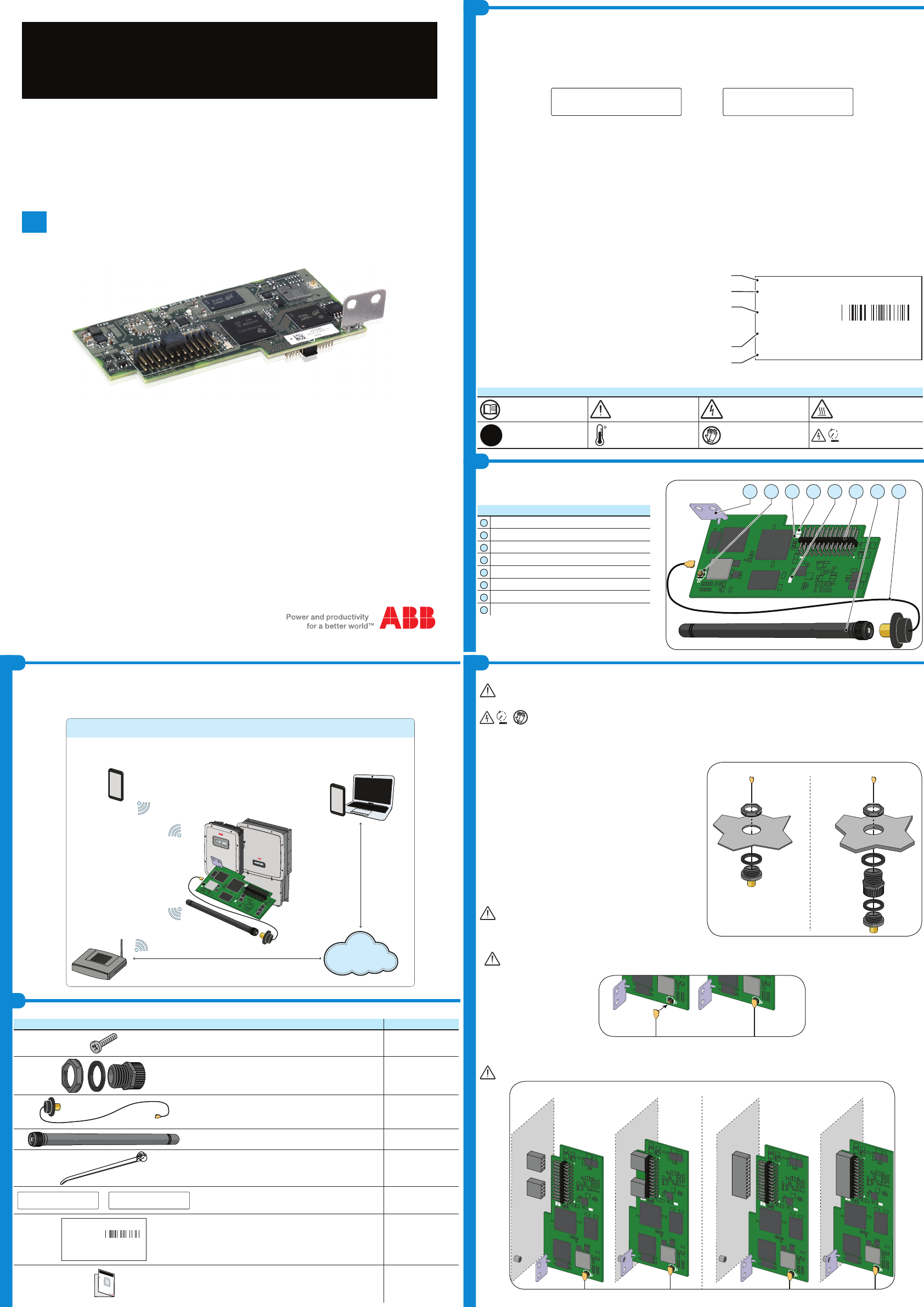
The main components of the VSN 300 WIFI LOGGER CARD are shown in the gure and described in the following table:
Main components
A
Antenna connection cable
B
Antenna (RF Technology Corp. Model EA-79 F RP SMA)
C
Connection terminals
D
Power LED
E
Status LED 2
F
Status LED 1
G
Coaxial connector
H
Mechanical mounting bracket
The printed wiring board of the VSN300 WIFI LOGGER CARD will be marked with the following information, identifying the product:
-Manufacturer Mark/Trade Mark
-CE (European Union) Marking
-RCM (Australia) Marking
-FCC ID
The FCC ID is FCC ID: X6W-3N16E when the WIFI LOGGER CARD is assembled with WiFi radio module supplied by Epcos
The FCC ID is FCC ID: X6W-3N16M when the WIFI LOGGER CARD is assembled with WiFi radio module supplied by Murata
A dedicated label including the FCC ID must be placed in a visible position on the exterior of the Inverter host equipment
Contains FCC ID: X6W-3N16E Contains FCC ID: X6W-3N16M
FCC (Federal Communications Commission) WARNING
1. This device complies with Part 15 of the FCC Rules. Operation is subject to the following two conditions:
(1) this device may not cause harmful interference, and (2) this device must accept any interference received, including interference that may cause undesired
operation
2. This equipment has been tested and found to comply with the limits for a Class B digital device, pursuant to Part 15 of the FCC Rules. These limits are desig-
ned to provide reasonable protection against harmful interference in a residential installation. This equipment generates, uses and can radiate radio frequency
energy and, if not installed and used in accordance with the instructions, may cause harmful interference to radio communications. However, there is no
guarantee that interference will not occur in a particular installation. If this equipment does cause harmful interference to radio or television reception, which
can be determined by turning the equipment off and on, the user is encouraged to try to correct the interference by one or more of the following measures:
-Reorient or relocate the receiving antenna.
-Increase the separation between the equipment and receiver.
-Connect the equipment into an outlet on a circuit different from that to which the receiver is connected.
-Consult the dealer or an experienced radio/TV technician for help.
3. RF Exposure. This device complies with Part 2.1091 of the FCC Rules for an uncontrolled environment. This equipment should be installed and operated with
a minimum distance of 20cm between the antenna and the user.
Refer to the specic section describing procedures how to integrate and use this device into the host xed mount inverter.
Changes or modications made to this equipment not expressly approved by the Manufacturer may void the FCC authorization to operate this equipment.
The identication label contained on the WIFI LOGGER CARD box have the information of the device and manufacturer.
In the manual and/or in some cases on the equipment, the danger or hazard zones are indicated with signs, labels, symbols or icons.
Symbols and icons
Always refer to instruction
manual
General warning - Important
safety information Hazardous voltage Hot surfaces
IP65
Protection rating of equip-
ment
Temperature range
Always use safety clothing
and/or personal safety
devices
Time need to discharge
stored energy
10
The packaging contains all the components required to correctly install and connect the VSN 300 WIFI LOGGER CARD:
Main components Quantity
Locking screw 1
Adaptor kit (Plastic lock nut, gasket and adaptor) 1 + 1 + 1
Antenna connection cable 1
WIFI antenna 1
Cable Tie 1
or
Contains FCC ID: X6W-3N16E Contains FCC ID: X6W-3N16M
FCC ID label 1
WIFI LOGGER CARD
SN: YYWWSSSSSS
MAC: XX-XX-XX-XX-XX-XX
PRODUCT KEY:XXXX-XXXX-XXXX-XXXX
Identication label 1
In addition to what is explained in this guide, the safety and installation information provided in the installation manual must be read and followed.
The technical documentation and the interface and management software for the product are available at the website.
XXXXXXXXXXXXXXXXXXX
XXXXXXXXXXXXXXXXXXX
ABB solar inverters
Thecnical documentation
J1
U8
U3
U11
U7
J2
1
2
23
24
U8
U3
U11
U7
GCBA
D
E
F
H
The WIFI LOGGER CARD allows to connect the inverter to a local LAN WIFI network via a wireless connection.
The WIFI LOGGER CARD features an integrated web server that enables to establish a direct connection to a PC,Smartphone or Tablet, allowing for board
conguration and local monitoring of the inverter.
When the inverter is connected to the WLAN network with access to the Internet, the VSN300 board allows to transfer data to the Aurora Vision Plant Viewer/
Aurora Vision® portal for remote monitoring purposes over an Internet browser or Mobile App (Aurora Vision Plant Viewer for Mobile)
APPLICATION WITH VSN300 WIFI LOGGER CARD
Aurora Vision
Aurora Vision Plant Viewer™
web platform
Aurora Vision
Plant Viewer for Mobile
VSN 300
WIFI LOGGER CARD
WI-FI router
®
INTERNET
POWER ALARM GFI ESC UP DOWN ENTER
TRIO
TRIO
POWER ALARM GFI ESC UP DOWN ENTER
J1
U8
U3
U11
U7
J2
1
2
23
24
Installation without adaptor Installation with adaptor
ABB
WIFI LOGGER CARD
SN: YYWWSSSSSS
MAC: XX-XX-XX-XX-XX-XX
PRODUCT KEY:XXXX-XXXX-XXXX-XXXX
- Manufacturer name
- Model name
- Serial Number composed by:
YY = Year of production
WW = Week of production
SSSSSS = progressive number
- WIFI LOGGER CARD Mac address
- Product Code composed by 16 characters used to activate the WIFI LOGGER CARD
7.
Commissioning
9.
Annex A
10.
Annex B
11.
Characteristics and technical data
Commissioning
VSN300 WiFI LOGGER CARD-Quick Installation Guide EN RevA
EFFECTIVE 2014-05-06
© Copyright 2014 ABB. All Rights Reserved.
Specications subject to change without notice.
Assembly Instructions
6.
Status LED behavior
WIFI LOGGER CARD
Communication
Inverter Interface Hyperlink (CAN@1 Mbps + RS485@115 kBaud) / Legacy (RS232 TTL @ 19.2 KBaud)
User Interface Wi-Fi® IEEE 802.11 b/g/n
Communication Protocols
LAN/WAN Protocols HTTPS, DHCP, NTP, SSL, SSH, XML, Modbus TCP (Sunspec)
Data Logging
Web User Interface Integrated
Local Monitoring wirelessly allowed via any Wi-Fi® device connecting the integrated WUI or running Plant Viewer for mobile
Remote Monitoring Plant Portfolio Manager® / Plant Viewer™ / Plant Viewer for mobile
Data Logging Specications
Data Sampling Rate High frequency data sampling (less than 1 minute average)
Local Storage Log data for 30 days based on 15-minute intervals
Upgradeability Remotely via Aurora Vision® Plant Management Platform / locally via Web User Interface
Advanced functionalities
Remote O&M operations Inverter’s parameters changing / inverter’ s rmware upgrade
Smart grid functionalities Grid control power-management enabled
Power Supply
DC Power Consumption ~ 2W
Environmental Parameters
Ambient Temperature Range -20°C...+85°C
Environmental Protection IP 20
Relative Humidity <85% Non-condensing
Mechanical Parameters (per unit)
Dimensions (H x W x D) 97mm x 46mm x 16mm (3.81’ x 1.81’ x 0.63’)
Weight 0.06 lbs (26g)
Mounting System inverter’s expansion slot
Compliance
Marking CE / FCC / RCM / Wi-Fi Certied™
Emissions FCC Part 15 Class B, CISPR 22, EN 55022 Conducted and radiated emission
Immunity EN55024
Remark. Features not specically listed in the present datasheet are not included in the product
Inverter connectors name for WIFI LOGGER CARD connection and adaptor kit necessity
Inverter model Connector(s) number and name Adaptor Kit
UNO-2.0/2.5-I-OUTD 2 connectors J6 and J15 Yes
PVI-3.0/3.6/4.2-TL-OUTD 2 connectors J14 and J23 No
PVI-3.8/4.6-I-OUTD 2 connectors J14 and J23 No
PVI-5000/6000-TL-OUTD 2 connectors J11 and J20 No
PVI-6.0/8.0/10.0/12.5-TL-OUTD 2 connectors J18 and J27 No
TRIO-5.8/7.5/8.5-TL-OUTD 1 connector J9 (SLOT 1) Yes
TRIO-20.0/27.6-TL-OUTD 2 connectors J14 and J11 No
Inverter compatibility table
Inverter model Monitoring Inverter family Monitoring Remote O&M Operations
UNO-2.0/2.5-I-OUTD Yes No
PVI-3.0/3.6/4.2-TL-OUTD Yes No
PVI-3.8/4.6-I-OUTD Yes No
PVI-5000/6000-TL-OUTD Yes No
PVI-6.0/8.0/10.0/12.5-TL-OUTD Yes No
TRIO-5.8/7.5/8.5-TL-OUTD Yes Yes
TRIO-20.0/27.6-TL-OUTD Yes No
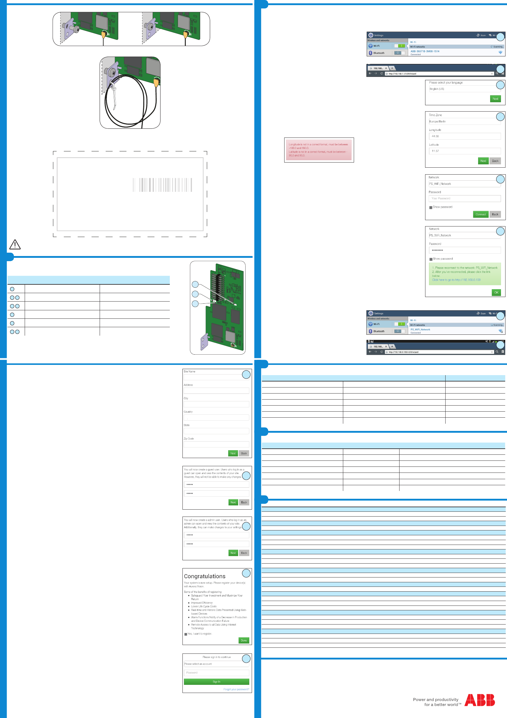
Provisioning of the WIFI LOGGER CARD with a Web Browser of a PC
1. Turn on the inverter by physically connecting the AC and DC voltages. The VSN300 WIFI LOGGER CARD will be automatically power up and after 60 secon-
ds acts like an access point where it is detectable by a tablet, smartphone or PC.
2. Activate the WiFi connection on the tablet/smartphone/PC and
connect it to the WLAN network established by the WIFI LOGGER
CARD denominated ABB_SSSSSS_PPPP_WWYY, where:
SSSSSS = Inverter serial number
PPPP = Inverter part number
WW=Week of production of the inverter
YY=Year of production of the inverter
3. Digit the default IP address 192.168.1.1 on an internet browser
4. Insert all the information required by the conguration wizard:
4a. Select the language
4b. Verify that the Time Zone, Longitude and Latitude of the installation site are correct or insert it if are
missing.
If the data are not in the correct format an instruction message will be displayed
4c. Select the “Home” WLAN network to which the WIFI LOGGER CARD must be connected for
monitoring purpose and insert the relative password
4d. When the WIFI LOGGER CARD is connected to the “Home” network, the IP address associated to
the WIFI card will be displayed by the wizard. Take note of this IP address that will be used in the
below steps of the commissioning procedure.
5. Switch the WIFI connection of the tablet/smartphone/PC to the
“Home” WLAN network to which the WIFI LOGGER CARD is
connected.
6. Digit the IP address associated to the WIFI card previously obtai-
ned at the step 4d. of the conguration wizard (in this example
192.168.0.100) on an internet browser.
The WIFI LOGGER CARD is equipped with 3 status led that can assume the following behavior:
LED LED Behavior Description
D
Blinking WIFI CARD powered
E
F
Alternating green and yellow ashing Start-up phase
E
F
Flashing green and yellow together Initializing Data Partition
E
Solid green Attached to WLAN
F
Solid yellow Provisioning Access Point Enabled
E
F
Both green and yellow ash 3 times together Inverter Serial Number Acquired
Contact us
www.abb.com/solarinverters
J1
U8
U3
U11
U7
J2
1
2
23
24
U8
U3
U11
U7
D
E
F
-Tighten the locking screw to x the WIFI board to the inverter. The screw secures the mounting bracket to the anchor point on the inverter.
J1
U8
U3
U11
U7
J2
1
2
23
24
J1
U8
U3
U11
U7
J2
1
2
23
24
-Fix the antenna connection cable to the hole on the mounting bracket using the supplied cable tie:
J1
U8
U3
U11
U7
J2
1
2
23
24
-At the end of installation phase, apply the following labels:
-FCC Label. This label is supplied with the VSN 300 WIFI LOGGER CARD and must be appiled near the Regulatory label of the inverter. The FCC label
contains the FCC ID of the WIFI LOGGER CARD.
-Identication label. This label is necessary to remember all the identication data of WIFI LOGGER CARD and is raccomended to apply it in the dedicated
area below.
WIFI LOGGER CARD
SN: YYWWSSSSSS
MAC: XX-XX-XX-XX-XX-XX
PRODUCT KEY:XXXX-XXXX-XXXX-XXXX
APPLY HERE THE
IDENTIFICATION LABEL
Save these instructions! The information reported in the above label could be used by the technical Service in case of problems.
4a
4b
4c
4d
5
2
3
7. Fill the site information
8. Create the User Name and Password of the guest user
Users who log in as a “guest” can open and view the contents of your site. However, they will not be able to make
any changes
9. Create the User Name and Password of the admin user
Users who log in as an “admin” can open and view the contents of your site. Additionally, they can make changes
to your settings.
10. End of the procedure. The system is now setup.
If you already have an Aurora Vision Plant Viewer/Aurora Vision® account click “done” and go to next step.
If you have not an Aurora Vision Plant Viewer/Aurora Vision® account put the check in the box “Yes, I want to
register” and click on “done”. You will be redirect to the Aurora Vision Plant Viewer registration procedure
11. Insert the Aurora Vision Plant Viewer/Aurora Vision® access credentials.
6
7
8
9
10
11