POWER ONE ITALY 3N16M WIFI LOGGER CARD User Manual

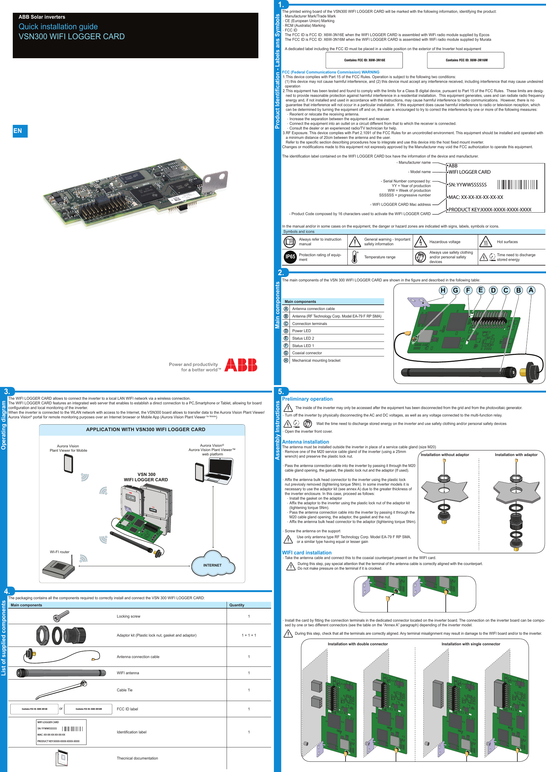
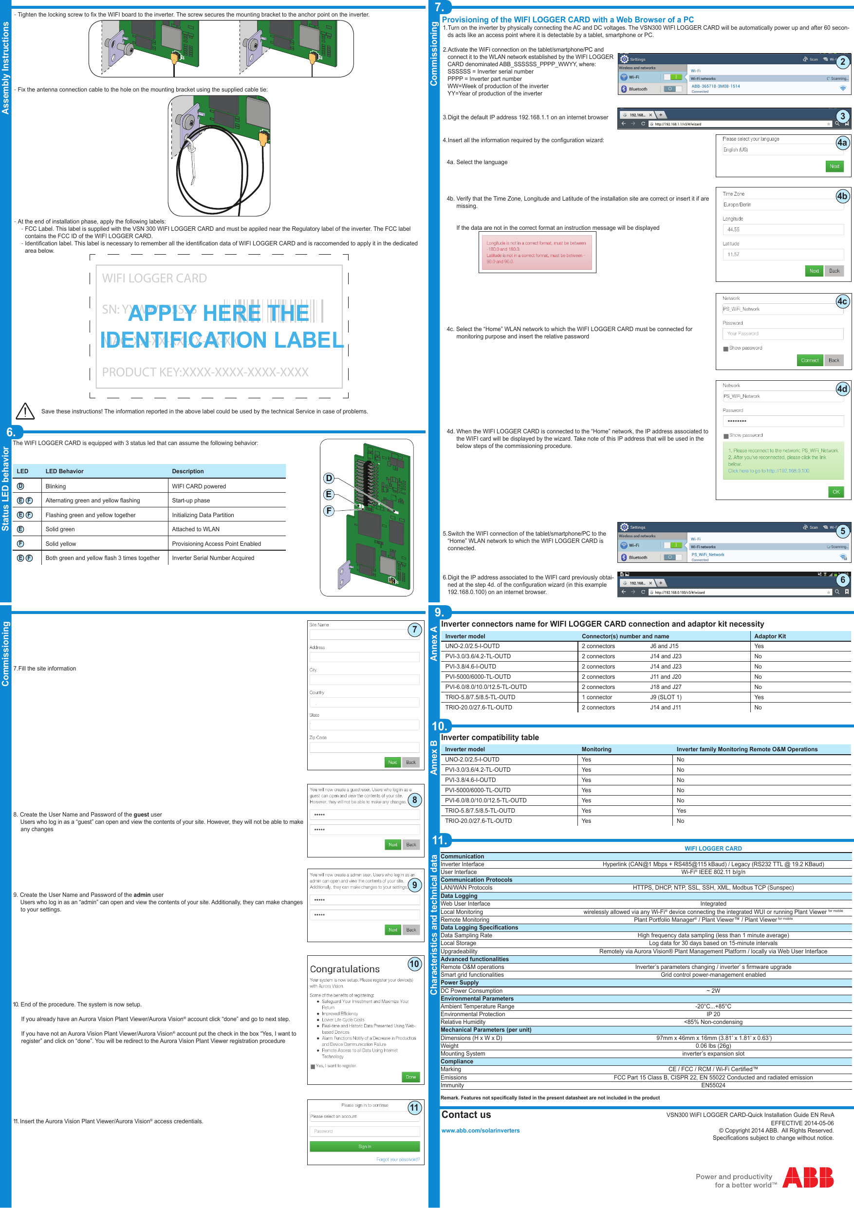
POWER-ONE ITALY SPA WIFI LOGGER CARD

User Manual

Quick installation guideVSN300 WIFI LOGGER CARD ABB Solar inverters1.Product Identication - Labels ans Symbols3.Operating diagram5.Assembly Instructions Main components2.List of supplied components4.ENPreliminary operationThe inside of the inverter may only be accessed after the equipment has been disconnected from the grid and from the photovoltaic generator. -Turn off the inverter by physically disconnecting the AC and DC voltages, as well as any voltage connected to the multi-function relay.10Wait the time need to discharge stored energy on the inverter and use safety clothing and/or personal safety devices -Open the inverter front cover. Antenna installationThe antenna must be installed outside the inverter in place of a service cable gland (size M20) -Remove one of the M20 service cable gland of the inverter (using a 25mm wrench) and preserve the plastic lock nut. -Pass the antenna connection cable into the inverter by passing it through the M20 cable gland opening, the gasket, the plastic lock nut and the adaptor (If used). -Afx the antenna bulk head connector to the inverter using the plastic lock nut previosly removed (tightening torque 5Nm). In some inverter models it is necessary to use the adaptor kit (see annex A) due to the greater thickness of the inverter enclosure. In this case, proceed as follows: -Install the gasket on the adaptor -Afx the adaptor to the inverter using the plastic lock nut of the adaptor kit (tightening torque 5Nm). -Pass the antenna connection cable into the inverter by passing it through the M20 cable gland opening, the adaptor, the gasket and the nut.  -Afx the antenna bulk head connector to the adaptor (tightening torque 5Nm). -Screw the antenna on the support Use only antenna type RF Technology Corp. Model EA-79 F RP SMA, or a similar type having equal or lesser gainWIFI card installation -Take the antenna cable and connect this to the coaxial counterpart present on the WIFI card.During this step, pay special attention that the terminal of the antenna cable is correctly aligned with the counterpart. Do not make pressure on the terminal if it is crooked.J1U8U3U11U7J2122324J1U8U3U11U7J2122324 -Install the card by tting the connection terminals in the dedicated connector located on the inverter board. The connection on the inverter board can be compo-sed by one or two different connectors (see the table on the “Annex A” paragraph) depending of the inverter model.During this step, check that all the terminals are correctly aligned. Any terminal misalignment may result in damage to the WIFI board and/or to the inverter.J1U8U3U11U7J2122324J1U8U3U11U7J2122324J1U8U3U11U7J2122324J1U8U3U11U7J2122324Installation with double connector Installation with single connectorThe main components of the VSN 300 WIFI LOGGER CARD are shown in the gure and described in the following table:Main componentsAAntenna connection cableBAntenna (RF Technology Corp. Model EA-79 F RP SMA)CConnection terminalsDPower LEDEStatus LED 2FStatus LED 1GCoaxial connectorHMechanical mounting bracketThe printed wiring board of the VSN300 WIFI LOGGER CARD will be marked with the following information, identifying the product: -Manufacturer Mark/Trade Mark -CE (European Union) Marking -RCM (Australia) Marking  -FCC IDThe FCC ID is FCC ID: X6W-3N16E when the WIFI LOGGER CARD is assembled with WiFi radio module supplied by EpcosThe FCC ID is FCC ID: X6W-3N16M when the WIFI LOGGER CARD is assembled with WiFi radio module supplied by MurataA dedicated label including the FCC ID must be placed in a visible position on the exterior of the Inverter host equipment Contains FCC ID: X6W-3N16E Contains FCC ID: X6W-3N16MFCC (Federal Communications Commission) WARNING1. This device complies with Part 15 of the FCC Rules. Operation is subject to the following two conditions: (1) this device may not cause harmful interference, and (2) this device must accept any interference received, including interference that may cause undesired operation2. This equipment has been tested and found to comply with the limits for a Class B digital device, pursuant to Part 15 of the FCC Rules.  These limits are desig-ned to provide reasonable protection against harmful interference in a residential installation.  This equipment generates, uses and can radiate radio frequency energy and, if not installed and used in accordance with the instructions, may cause harmful interference to radio communications.  However, there is no guarantee that interference will not occur in a particular installation.  If this equipment does cause harmful interference to radio or television reception, which can be determined by turning the equipment off and on, the user is encouraged to try to correct the interference by one or more of the following measures: -Reorient or relocate the receiving antenna. -Increase the separation between the equipment and receiver. -Connect the equipment into an outlet on a circuit different from that to which the receiver is connected. -Consult the dealer or an experienced radio/TV technician for help.3. RF Exposure. This device complies with Part 2.1091 of the FCC Rules for an uncontrolled environment. This equipment should be installed and operated with a minimum distance of 20cm between the antenna and the user.Refer to the specic section describing procedures how to integrate and use this device into the host xed mount inverter.Changes or modications made to this equipment not expressly approved by the Manufacturer may void the FCC authorization to operate this equipment.The identication label contained on the WIFI LOGGER CARD box have the information of the device and manufacturer.In the manual and/or in some cases on the equipment, the danger or hazard zones are indicated with signs, labels, symbols or icons.Symbols and iconsAlways refer to instruction manualGeneral warning - Important safety information Hazardous voltage Hot surfacesIP65Protection rating of equip-ment    Temperature rangeAlways use safety clothing and/or personal safety devicesTime need to discharge stored energy10The packaging contains all the components required to correctly install and connect the VSN 300 WIFI LOGGER CARD:Main components QuantityLocking screw 1Adaptor kit (Plastic lock nut, gasket and adaptor) 1 + 1 + 1Antenna connection cable 1WIFI antenna 1Cable Tie 1orContains FCC ID: X6W-3N16E Contains FCC ID: X6W-3N16MFCC ID label 1WIFI LOGGER CARDSN: YYWWSSSSSSMAC: XX-XX-XX-XX-XX-XXPRODUCT KEY:XXXX-XXXX-XXXX-XXXXIdentication label 1In addition to what is explained in this guide, the safety and installation information provided in the installation manual must be read and followed.The technical documentation and the interface and management software for the product are available at the website.XXXXXXXXXXXXXXXXXXXXXXXXXXXXXXXXXXXXXXABB solar invertersThecnical documentationJ1U8U3U11U7J2122324U8U3U11U7GCBADEFHThe WIFI LOGGER CARD allows to connect the inverter to a local LAN WIFI network via a wireless connection. The WIFI LOGGER CARD features an integrated web server that enables to establish a direct connection to a PC,Smartphone or Tablet, allowing for board conguration and local monitoring of the inverter.When the inverter is connected to the WLAN network with access to the Internet, the VSN300 board allows to transfer data to the Aurora Vision Plant Viewer/Aurora Vision® portal for remote monitoring purposes over an Internet browser or Mobile App (Aurora Vision Plant Viewer for Mobile)APPLICATION WITH VSN300 WIFI LOGGER CARDAurora Vision   Aurora Vision Plant Viewer™ web platformAurora Vision Plant Viewer for MobileVSN 300WIFI LOGGER CARD WI-FI router ®INTERNETPOWER       ALARM         GFI                  ESC          UP          DOWN        ENTERTRIOTRIOPOWER       ALARM         GFI                  ESC          UP          DOWN        ENTERJ1U8U3U11U7J2122324Installation without adaptor Installation with adaptorABBWIFI LOGGER CARDSN: YYWWSSSSSSMAC: XX-XX-XX-XX-XX-XXPRODUCT KEY:XXXX-XXXX-XXXX-XXXX- Manufacturer name- Model name- Serial Number composed by:YY = Year of productionWW = Week of productionSSSSSS = progressive number- WIFI LOGGER CARD Mac address- Product Code composed by 16 characters used to activate the WIFI LOGGER CARD
7.Commissioning9.Annex A10.Annex B11.Characteristics and technical dataCommissioningVSN300 WiFI LOGGER CARD-Quick Installation Guide EN RevAEFFECTIVE 2014-05-06© Copyright 2014 ABB.  All Rights Reserved.Specications subject to change without notice.   Assembly Instructions6.Status LED behaviorWIFI LOGGER CARDCommunicationInverter Interface Hyperlink (CAN@1 Mbps + RS485@115 kBaud) / Legacy (RS232 TTL @ 19.2 KBaud)User Interface Wi-Fi® IEEE 802.11 b/g/nCommunication ProtocolsLAN/WAN Protocols HTTPS, DHCP, NTP, SSL, SSH, XML, Modbus TCP (Sunspec)Data LoggingWeb User Interface IntegratedLocal Monitoring wirelessly allowed via any Wi-Fi® device connecting the integrated WUI or running Plant Viewer for mobileRemote Monitoring Plant Portfolio Manager® / Plant Viewer™ / Plant Viewer for mobileData Logging SpecicationsData Sampling Rate High frequency data sampling (less than 1 minute average)Local Storage Log data for 30 days based on 15-minute intervalsUpgradeability Remotely via Aurora Vision® Plant Management Platform / locally via Web User InterfaceAdvanced functionalitiesRemote O&M operations Inverter’s parameters changing / inverter’ s rmware upgradeSmart grid functionalities Grid control power-management enabledPower SupplyDC Power Consumption ~ 2WEnvironmental ParametersAmbient Temperature Range -20°C...+85°CEnvironmental Protection IP 20Relative Humidity <85% Non-condensingMechanical Parameters (per unit)Dimensions (H x W x D)  97mm x 46mm x 16mm (3.81’ x 1.81’ x 0.63’)Weight 0.06 lbs (26g)Mounting System inverter’s expansion slotComplianceMarking CE / FCC / RCM / Wi-Fi Certied™Emissions FCC Part 15 Class B, CISPR 22, EN 55022 Conducted and radiated emissionImmunity EN55024Remark. Features not specically listed in the present datasheet are not included in the productInverter connectors name for WIFI LOGGER CARD connection and adaptor kit necessityInverter model Connector(s) number and name Adaptor KitUNO-2.0/2.5-I-OUTD 2 connectors J6 and J15 YesPVI-3.0/3.6/4.2-TL-OUTD 2 connectors J14 and J23 NoPVI-3.8/4.6-I-OUTD 2 connectors J14 and J23 NoPVI-5000/6000-TL-OUTD 2 connectors J11 and J20 NoPVI-6.0/8.0/10.0/12.5-TL-OUTD 2 connectors J18 and J27 NoTRIO-5.8/7.5/8.5-TL-OUTD 1 connector J9 (SLOT 1) YesTRIO-20.0/27.6-TL-OUTD 2 connectors J14 and J11 NoInverter compatibility tableInverter model Monitoring Inverter family Monitoring Remote O&M OperationsUNO-2.0/2.5-I-OUTD Yes NoPVI-3.0/3.6/4.2-TL-OUTD Yes NoPVI-3.8/4.6-I-OUTD Yes NoPVI-5000/6000-TL-OUTD Yes NoPVI-6.0/8.0/10.0/12.5-TL-OUTD Yes NoTRIO-5.8/7.5/8.5-TL-OUTD Yes YesTRIO-20.0/27.6-TL-OUTD Yes NoProvisioning of the WIFI LOGGER CARD with a Web Browser of a PC1. Turn on the inverter by physically connecting the AC and DC voltages. The VSN300 WIFI LOGGER CARD will be automatically power up and after 60 secon-ds acts like an access point where it is detectable by a tablet, smartphone or PC.2. Activate the WiFi connection on the tablet/smartphone/PC and connect it to the WLAN network established by the WIFI LOGGER CARD denominated ABB_SSSSSS_PPPP_WWYY, where:SSSSSS = Inverter serial numberPPPP = Inverter part numberWW=Week of production of the inverterYY=Year of production of the inverter3. Digit the default IP address 192.168.1.1 on an internet browser4. Insert all the information required by the conguration wizard:   4a. Select the language   4b. Verify that the Time Zone, Longitude and Latitude of the installation site are correct or insert it if are         missing.         If the data are not in the correct format an instruction message will be displayed        4c. Select the “Home” WLAN network to which the WIFI LOGGER CARD must be connected for          monitoring purpose and insert the relative password   4d. When the WIFI LOGGER CARD is connected to the “Home” network, the IP address associated to         the WIFI card will be displayed by the wizard. Take note of this IP address that will be used in the         below steps of the commissioning procedure.5. Switch the WIFI connection of the tablet/smartphone/PC to the “Home” WLAN network to which the WIFI LOGGER CARD is connected.6. Digit the IP address associated to the WIFI card previously obtai-ned at the step 4d. of the conguration wizard (in this example 192.168.0.100) on an internet browser.The WIFI LOGGER CARD is equipped with 3 status led that can assume the following behavior:LED LED Behavior DescriptionDBlinking WIFI CARD poweredE FAlternating green and yellow ashing Start-up phaseE FFlashing green and yellow together Initializing Data PartitionESolid green Attached to WLANFSolid yellow Provisioning Access Point EnabledE FBoth green and yellow ash 3 times together Inverter Serial Number AcquiredContact uswww.abb.com/solarinvertersJ1U8U3U11U7J2122324U8U3U11U7DEF -Tighten the locking screw to x the WIFI board to the inverter. The screw secures the mounting bracket to the anchor point on the inverter.J1U8U3U11U7J2122324J1U8U3U11U7J2122324 -Fix the antenna connection cable to the hole on the mounting bracket using the supplied cable tie:J1U8U3U11U7J2122324 -At the end of installation phase, apply the following labels: -FCC Label. This label is supplied with the VSN 300 WIFI LOGGER CARD and must be appiled near the Regulatory label of the inverter. The FCC label contains the FCC ID of the WIFI LOGGER CARD. -Identication label. This label is necessary to remember all the identication data of WIFI LOGGER CARD and is raccomended to apply it in the dedicated area below.  WIFI LOGGER CARDSN: YYWWSSSSSSMAC: XX-XX-XX-XX-XX-XXPRODUCT KEY:XXXX-XXXX-XXXX-XXXXAPPLY HERE THE IDENTIFICATION LABELSave these instructions! The information reported in the above label could be used by the technical Service in case of problems.4a4b4c4d5237. Fill the site information 8.  Create the User Name and Password of the guest user     Users who log in as a “guest” can open and view the contents of your site. However, they will not be able to make        any changes9.  Create the User Name and Password of the admin user     Users who log in as an “admin” can open and view the contents of your site. Additionally, they can make changes      to your settings.10.    End of the procedure. The system is now setup.If you already have an Aurora Vision Plant Viewer/Aurora Vision® account click “done” and go to next step.If you have not an Aurora Vision Plant Viewer/Aurora Vision® account put the check in the box “Yes, I want to register” and click on “done”. You will be redirect to the Aurora Vision Plant Viewer registration procedure11.   Insert the Aurora Vision Plant Viewer/Aurora Vision® access credentials.67891011

Navigation menu