PROFORM Treadmill Manual L0520508
User Manual: PROFORM PROFORM Treadmill Manual PROFORM Treadmill Owner's Manual, PROFORM Treadmill installation guides
Open the PDF directly: View PDF ![]() .
.
Page Count: 22
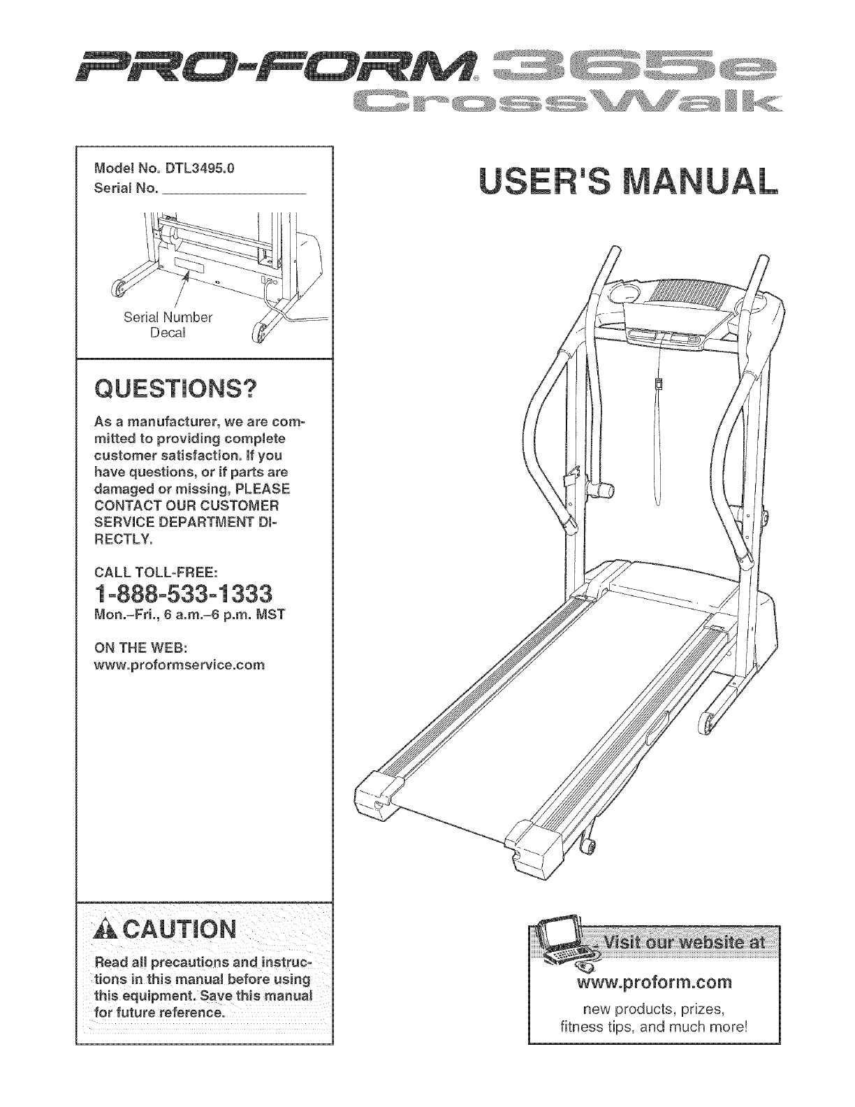
Model No. DTL3495.0
Serial No.
SeriaU Number
DecaU
J \
As a manufacturer, we are com-
mitted to providing complete
customer satisfaction. If you
have questions, or if parts are
damaged or missing, PLEASE
CONTACT OUR CUSTOMER
SERVICE DEPARTMENT DI-
RECTLY.
CALL TOLL-FREE:
1o888o533ol 333
Mon.=Fri., 6 a.m.=6 p.m. MST
ON THE WEB:
www.proformservice.com
,_ CAUTION
Read all precautions and instruc-
tions in this manual before using
this equipment. Save this manual
for future reference.
'S
www.proformocom
new products, prizes,
fitness tips, and much more!
TABLE OF CONTENTS
iMPORTANT PRECAUTIONS ................................................................ 3
BEFORE YOU BEGIN ...................................................................... 5
ASSEMBLY ............................................................................... 6
OPERATHON AND ADJUSTMENT ............................................................ 10
HOW TO FOLD AND MOVE THE TREADMHLL .................................................. 14
TROUBLESHOOTHNG ..................................................................... 16
CONDHTHONHNGGUHDELHNES ............................................................... 18
ORDERHNG REPLACEMENT PARTS .................................................. Back Cover
LHMHTEDWARRANTY .............................................................. Back Cover
Note: An EXPLODED DRAWING and a PART LiST are attached in the center of this manual,
PROFORM is a registered trademark of iCON IP, Inc,
2
iMPORTANT PRECAUTIONS
WARN ING:To reduce the riskofburns,fire,electric shock, or injuryto persons, read the
followmg important precautions and information before operating the treadmill.
1. it is the responsibility of the owner to ensure
that all users of this treadmill are adequately
informed of aH warnings and precautions.
2. Use the treadmill only as described.
3. Place the treadmill on a leveJ surface, with at
least eight feet of clearance behind it and two
feet on each side. Do not place the treadmill
on any surface that bJocke air openings. To
protect the floor or carpet from damage, place
a mat under the treadmill
4. Keep the treadmill indoors, away from moieo
ture and dust. Do not put the treadmill in a
garage or covered patio, or near water.
5. De not operate the treadmill where aerosol
products are used or where oxygen is being
administered.
8. Keep children under the age of 12 and pets
away from the treadmill at all times.
7. The treadmill should be used onty by persons
weighing 250 pounds or less.
8. Never allow more than one person on the
treadmill at a time.
12. Failure to use a properly functioning surge
suppressor could result in damage to the con=
troJ system of the treadmill if the control sys-
tem is damaged, the walking belt may change
speed, accelerate, or stop unexpectedJy,
which may result in a fall and serious injury.
13. Keep the power cord and the surge suppres-
sor away from heated surfaces.
14. Never move the waJking belt while the power
is turned off. Do not operate the treadmill if
the power cord or plug is damaged, or if the
treadmiJl is not working properly. (See BE-
FORE YOU BEGmNon page 5 if the treadmill is
not working properly.)
15. Never start the treadmiiJ whiJe you are stand-
ing on the walking beJt. AJwaye hold the
handrails while using the treadmill.
18.The treadmill is capable of high speeds.
Adiust the speed in emaJJ increments to avoid
sudden jumps inspeed.
17. The putse sensor is not a medical device.
Various factors, including your movement,
may affect the accuracy of heart rate readings.
The sensor is intendedonly as an exerciseaid
9. Wear appropriate exercise clothes when in determining heart rate trends in general
using the treadmill Do not wear loose clothes
that could become caught in the treadmill 18. Do not use the hand weights at speeds faster
AtHetic support clothes are recommended for than waJking speeds. Using weights and not
both men and women. Always wear athletic
shoes. Never use the treadmillwith bare feet,
wearing only stockings,or//7sandals.
10. When connecting the power cord (see page 10),
plug the power cord into a surge suppressor
(not included) and p|ug _he surge suppressor
into a grounded circuit capabne of carrying 15
or more amps. No other appliance should be on
the same circuit. Do not use an extension cord.
11, Use only a eingJe-ouUet surge suppressor that
meets aH of the specifications described on
page 10. To purchase a surge suppressor, see
your local PROFORM dealer or call the toHo
free teJephone number on the front cover of
this manual and order part number 148148, or
see your local electronics store.
holding the handrails may compromise your
ability to maintain your balance. Exercises
using weights shouJd be attempted only by
experienced users.
19. Never leave the treadmill unattended while it
is tanning. A_waye remove the key and unplug
the power cord when the treadmill is not in
use.
20. Do not attempt to raise, _ower. or move the
treadmH_ unti_ it is propedy assembled. (See
ASSEMBLY on page 8, and HOW TO FOLD
AND MOVE THE TREADMILL on page 14.)
You must be able to eafe_y Hft 45 pounds (28
kg) to raise, _ower, or move the treadmill.
21.Whenfoldingor movingthetreadmill,make maintenanceandadjustmentproceduresde-
surethatthe storagelatch is fully closed, scribed in this manual. Never remove the
motor hood unless instructed to do so by an
22. inspect and properly tighten all parts of the authorized service representative. Servicing
treadmill regularly, other than the procedures in this manual
should be performed by an authorized set-
23. Never insert any object into any opening, vice representative only.
24.DANG ER: Alw,ysuop_ugthepower =5.Thi,treadm,_i, _nteodedforin-homeuse
cord immediateJy after use, before cleaning onJy. Do not use this treadmill in a commer*
the treadmill, and before performing the cial, rentaJ, or institutional setting.
_a_WARNING: Beforebeginningth_sor,nyexerciseprogram,consultyourphys_cion.Th_s
is especially important for persons over the age of 35 or persons with pro=existing health problems.
Read aJl instructions before using, iCON assumes no responsibility for personal injury or property
damage sustained by or through the use of this product.
SAVE THESE iNSTRUCTiONS
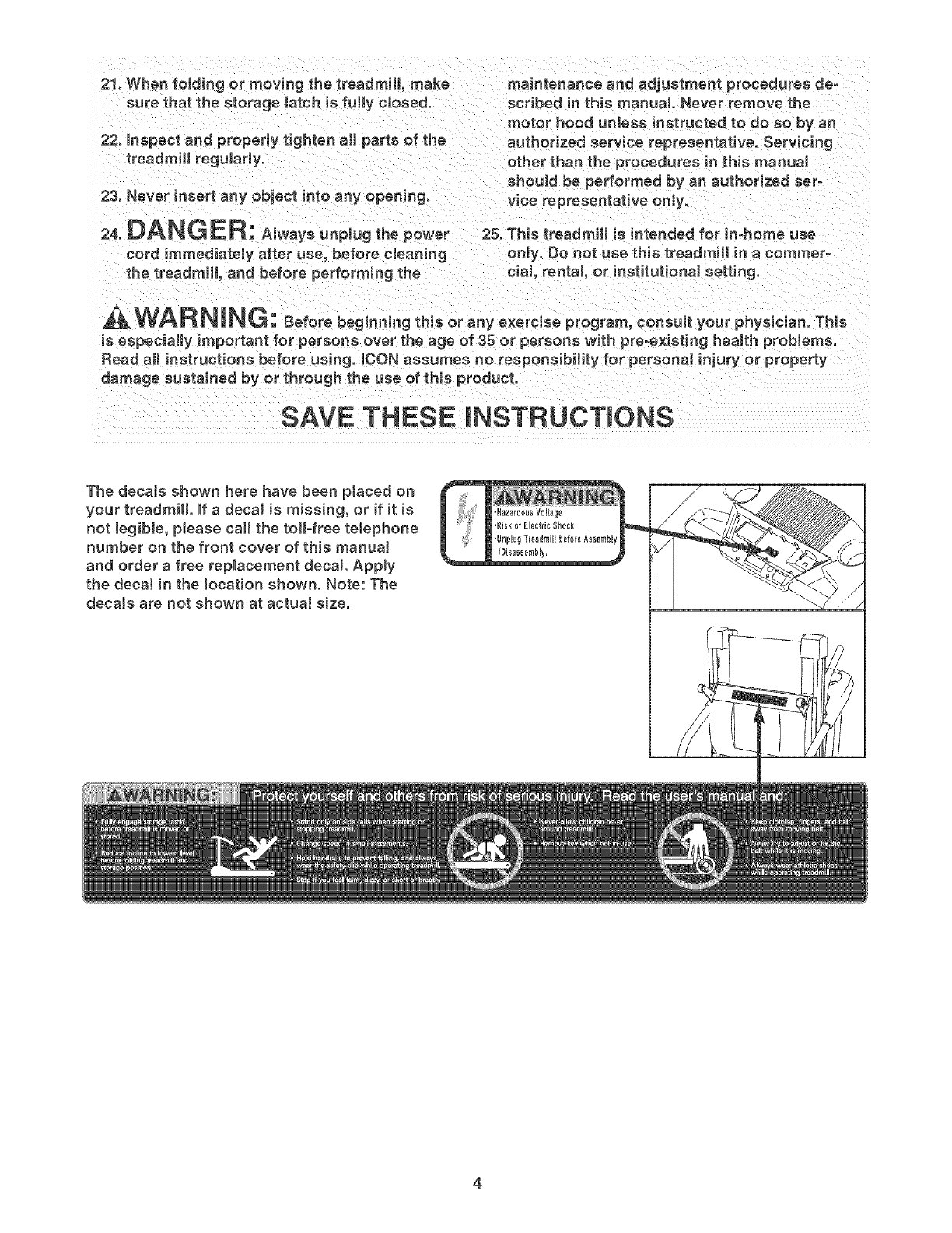
The decaJs shown here have been ptaced on
your treadmill. If a decal is missing, or if it is
not legible, please call the toll-free telephone
number on the front cover of this manua!
and order a free replacement decal Appty
the decal in the location shown. Note: The
decals are not shown at actual size.
4
BEFORE YOU BEGIN
Thank you for sebcting the new PROFORM _ CROSS-
WALK 365e treadmill The CROSSWALK 365e treadmHU
combines advanced technobgy with innovative design
to heUpyou get the most from your exercise in the con-
venience of your home, And when you're not exercising,
the CROSSWALK 365e treadmHUcan be foUdedup, re-
quiring bss than haft the floor space of other treadmHb,
For your benefit, read this manuat carefully before
using the treadmill, if you have questions after read-
ing this manual see the front cover of this manual To
heUpus assist you, phase note the product modeU
number and sedaUnumber before calling, The modeU
number of the treadmill is DTL3495,0, The serial num-
ber can be found on a decal attached to the treadmill
(see the front cover of this manual for the location),
To avoid a registration fee for any service needed
under warranty, you must register the treadmill at
www.proformservice.com/registration.
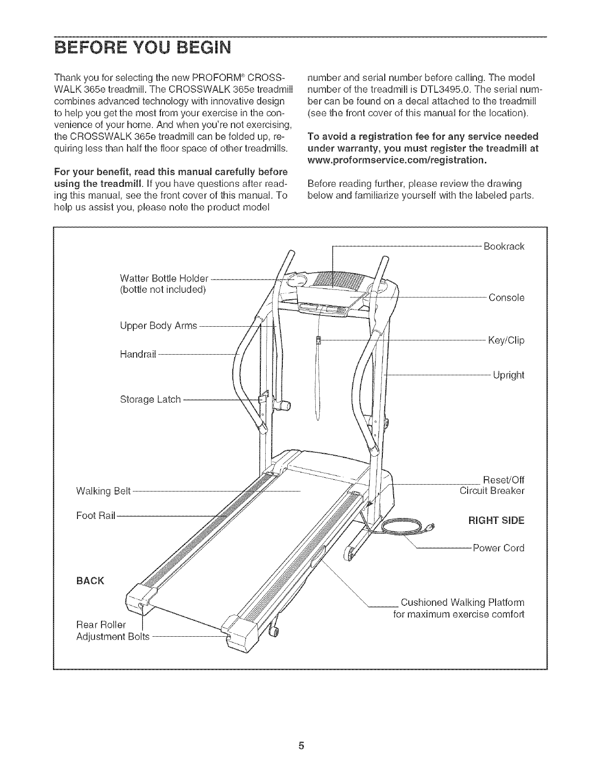
Before reading further, please review the drawing
below and familiarize yourself with the labeled parts,
Bookrack
Watter Bottle Holder
(bottle not included) Console
Upper Body Arms
Handrail
Storage Latch
Key/Clip
Upright
Walking Belt
Foot Rail
Reset/Off
Circuit Breaker
RIGHT SIDE
Power Cord
BACK
Rear Roller
Walking Platform
for maximum exercise comfort
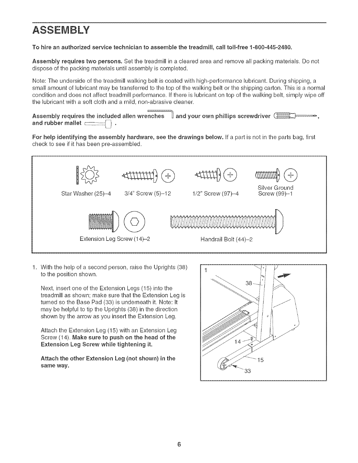
To hire an authorized service technician to assemble the treadmill, call toll-free 1-800-445-2480.
AssembJy requires two persons. Set the treadmHUin a cbared area and remove aH packing materiaUs, Do not
dispose of the packing materiaUsuntil assemMy is compbted,
Note: The underside of the treadmHUwaUking beUtis coated with high-performance Uubrbant, During shipping, a
small amount of Uubrbant may be transferred to the top of the waUking belt or the shipping carton, This is a normal
condition and does not affect treadmill performance, If there is lubricant on top of the walking belt, simply wipe off
the lubricant with a soft cloth and a mild, non-abrasive cleaner,
E
Assembly requires the included allen wrenches _ and your own philtips screwdriver
and rubber mallet _,-_ .
For help identifying the assembJy hardware, see the drawings below. If a part is not in the parts bag, first
check to see if it has been pre-assembbd,
Star Washer (25)-4 3/4" Screw (5)-12 1/2" Screw (97)-4 Silver Ground
Screw (99)-1
Extension Leg Screw (14)-2 Handrail Bolt (44)-2
1, With the help of a second person, raise the Uprights (38)
to the position shown,
Next, insert one of the Extension Legs (15) into the
treadmill as shown; make sure that the Extension Leg is
turned so the Base Pad (33) is underneath it, Note: it
may be helpful to tip the Uprights (38) in the direction
shown by the arrow as you insert the Extension Leg,
Attach the Extension Leg (15) with an Extension Leg
Screw (14), Make sure to push on the head of the
Extension Leg Screw while tightening it.
Attach the other Extension Leg (not shown) in the
same way. 33
15
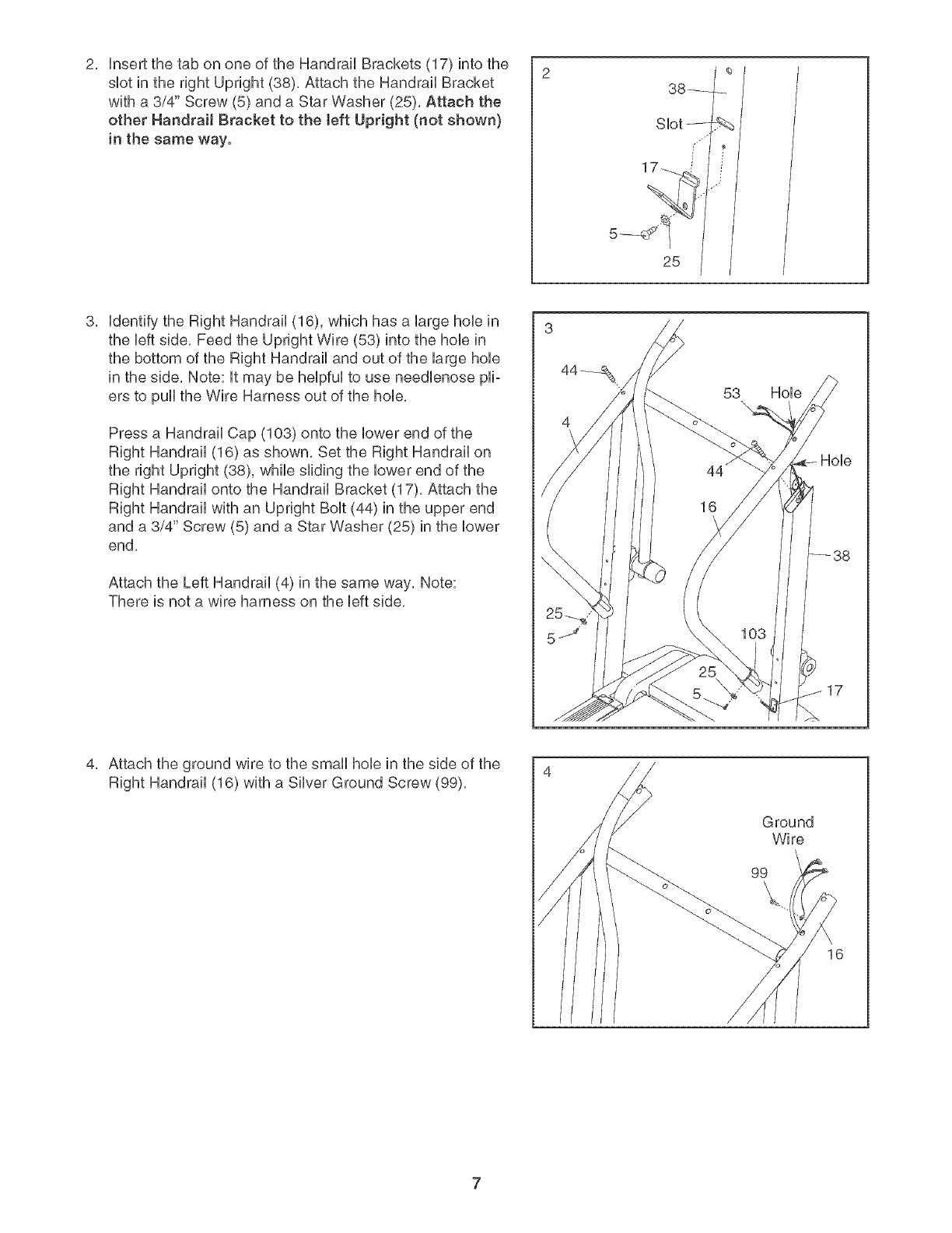
InsertthetabononeoftheHandrailBrackets(17)intothe
suetintherightUpright(38),AttachtheHandrailBracket
witha3/4"Screw(5)anda StarWasher(25),Attachthe
otherHandrailBracketto theleft Upright(not shown}
in the same way. Slot
1 ffi
25
Udentifythe Right Handrail (16), which has a UargehoUein
the Ueftside, Feed the Upright Wire (53) into the hoUein
the bottom of the Right Handrail and out of the large hoUe
in the side, Note: Utmay be heUpfuUto use needUenose pHo
ers to pull the Wire Harness out of the hoUe,
Press a Handrail Cap (103) onto the Uowerend of the
Right Handrail (16) as shown, Set the Right Handrail on
the right Upright (38), while sliding the lower end of the
Right Handrail onto the Handrail Bracket (17), Attach the
Right Handrail with an Upright Bolt (44) in the upper end
and a 3/4" Screw (5) and a Star Washer (25) in the lower
end,
Attach the Left Handrail (4) in the same way, Note:
There is not a wire harness on the left side,
53 Hole
Attach the ground wire to the small hole in the side of the
Right Handrail (16) with a Silver Ground Screw (99),
Ground
Wire
99\

5, 5 87
Loosen the two (one shown) Crossbar Screws (98) sevo
eral turns, Place the Console Base (87) on the Right
Handrail (16) and the Left Handrail (not shown), Make
sure that the Wire Harness is not pinched in the Right
Handrail. Attach the Consob Base with four 3/#' Screws
(5) (onUytwo Screws are shown), Start all four 3/4"
Screws before tightening them.
insert the Wire Harness (53) through the two indicated
pDstb ties on the Consob Base (87), Next, insert the
Wire Harness up through the opening beside the Wire
Cover (10), Make sure that the Wire Cover is secureUyat-
tached to the Consob Base,
See the inset drawing, Look at the top of the Consob
Base (87), insert the Wire Harness (53) through the pUaso
tic tie on top of the Consob Base,
HoUdthe Consob (10) near the Consob Base (87),
Touch the Right Handrail (16} to discharge any static.
See the inset drawing, Find the 2owire connector on the
end of the Wire Harness (53), insert the connector into
the red connector beneath the Consob, The connectors
should slide together easily and snap into place. If
they do not, turn the connector and then insert it, Insert
the 6owire connector into the socket beneath the Console
the same way,
Insert the excess Wire Harness (53) down through the
opening in the Console Base (87 [see the inset drawing
in step 5]), SecureJy tighten the plastic tie on top of
the Consote Base to prevent the Wire Harness from
slipping. Then, cut off the end of the plastic tie,
Make sure that the connectors and wires appear as
shown at the right, IF THE CONNECTORS ARE NOT
INSERTED PROPERLY, THE CONSOLE MAY BE
DAMAGED WHEN THE POWER IS TURNED ON.
See drawing 6a, Press the Bookrack (85) onto the Console
Base (87) in the location shown,
Set the Console (10) on the Console Base (87), insert
the excess Wire Harness (53) into the large hob in the
side of the Right Handrail (16), Securely tighten the
plastic ties on the bottom of the Console Base to
prevent the Wire Harness from slipping. Then, cut off
the ends of the plastic ties,
Attach the Console (10) to the Console Base (87) with two
3/#' Screws (5) and four 1/2" Screws (97), Start aH six
Screws before tightening them; do not overtighten
the Screws. Tighten the two Crossbar Screws (98) (only
one is shown),
Ties
6a
Ties
53 10
98
,16
/
\97 97
©
6owire
2owire
87
8
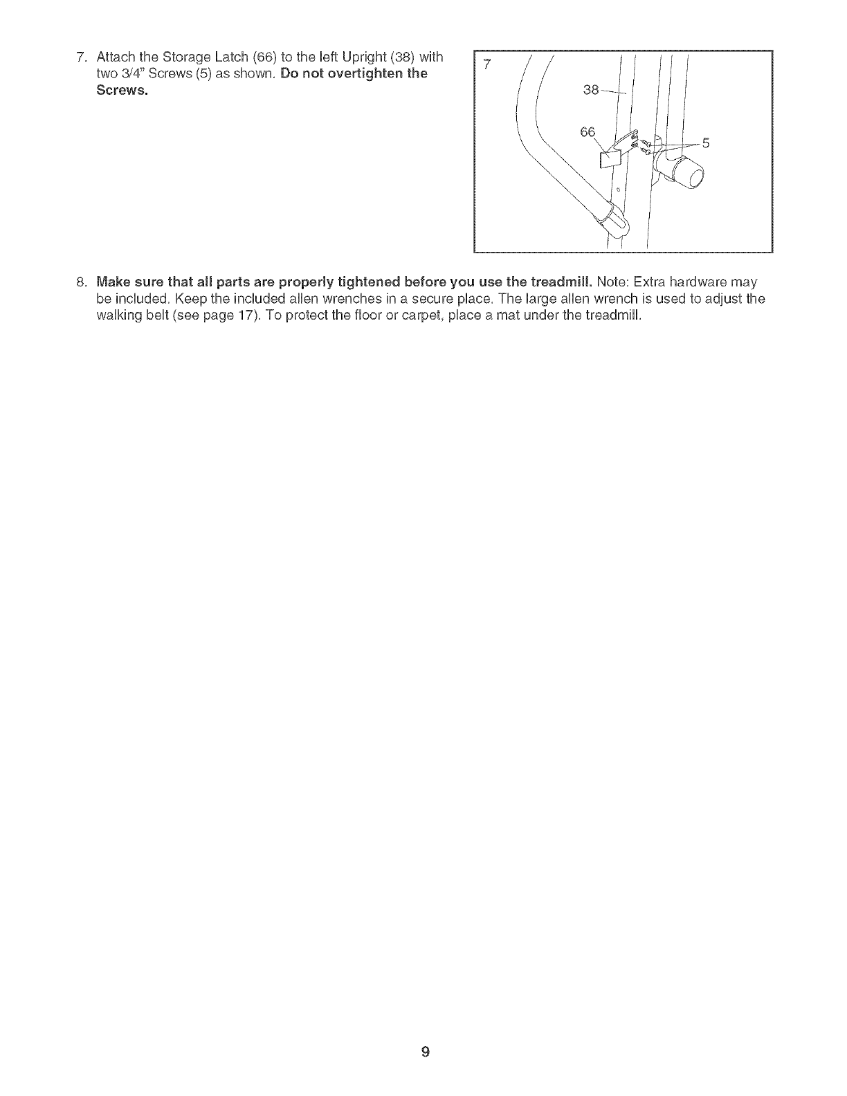
7, 7
Attach the Storage Latch (66) to the UeftUpright (38) with
two 3/4" Screws (5) as shown, Do not overtighten the
Screws.
8, Make sure that all parts are properly tightened before you use the treadmill. Note: Extra hardware may
be incUuded, Keep the incUuded allen wrenches in a secure pUace,The large allen wrench is used to adjust the
waUking beUt(see page 17), To protect the floor or carpet, pUacea mat under the treadmill
OPERATmON AND ADJUSTMENT
THE PRE-LUBRICATED WALKING BELT
Your treadmHUfeatures a waUking beUtcoated with high°
performance Uubrbant, IMPORTANT: Never apply sil-
icone spray or other substances to the waJking
beJt or the walking platform. Such substances will
deteriorate the walking belt and cause excessive
wear.
HOW TO PLUG IN THE POWER CORD
DANG ER: Improperconnection
of the equipment-grounding conductor can
resuJt in an increased risk of eJectric shock.
Check with a qualified eJectrician or service-
man if you are in doubt as to whether the
product is properly grounded. Do not modify
the plug provided with the productJif it wHJ
not fit the outlet, have a proper ouUet
installed by a quaJified eJectrician.
Your treadmill, like any other type of sophisticated
electronic equipment, can be seriously damaged by
sudden voltage changes in your home's power,
Voltage surges, spikes, and noise interference can
result from weather conditions or from other appliances
being turned on or off, To decrease the possibility of
your treadmill being damaged, always use a surge
suppressor with your treadmill (see drawing 1 at
the right}. To purchase a surge suppressor, see
your JocaJ PROFORM deaJer or call the toll-free
teJephone number on the front cover of this man-
ual and order part number 146148, or see your JocaJ
electronics store.
Use onJy a single-outlet surge suppressor that is
UL 1449 Jisted as a transient voltage surge sup-
pressor (TVSS}. The surge suppressor must have a
UL suppressed vottage rating of 400 volts or Jess
and a minimum surge dissipation of 450 joules.
The surge suppressor must be electrically rated for
120 volts AC and 15 amps. There must be a moni-
toring Hght on the surge suppressor to indicate
whether it is functioning properly. Failure to use a
properJy functioning surge suppressor could resuJt
in damage to the controt system of the treadmill. If
the control system is damaged, the waJking belt
may change speed, acceJerate or stop unexpect-
edly, which may result in a fail and serious injury.
This product must be grounded, if it should maifunc°
tion or break down, grounding provides a path of least
resistance for electric current to reduce the risk of ebc°
tric shock. This product is equipped with a cord having
an equipment-grounding conductor and a grounding
plug, Plug the power cord into a surge suppressor,
and pJug the surge suppressor into an appropriate
outlet that is properJy installed and grounded in
accordance with aH JocaJ codes and ordinances.
Important: The treadmill is not compatible with
GFOl-equipped outJets.
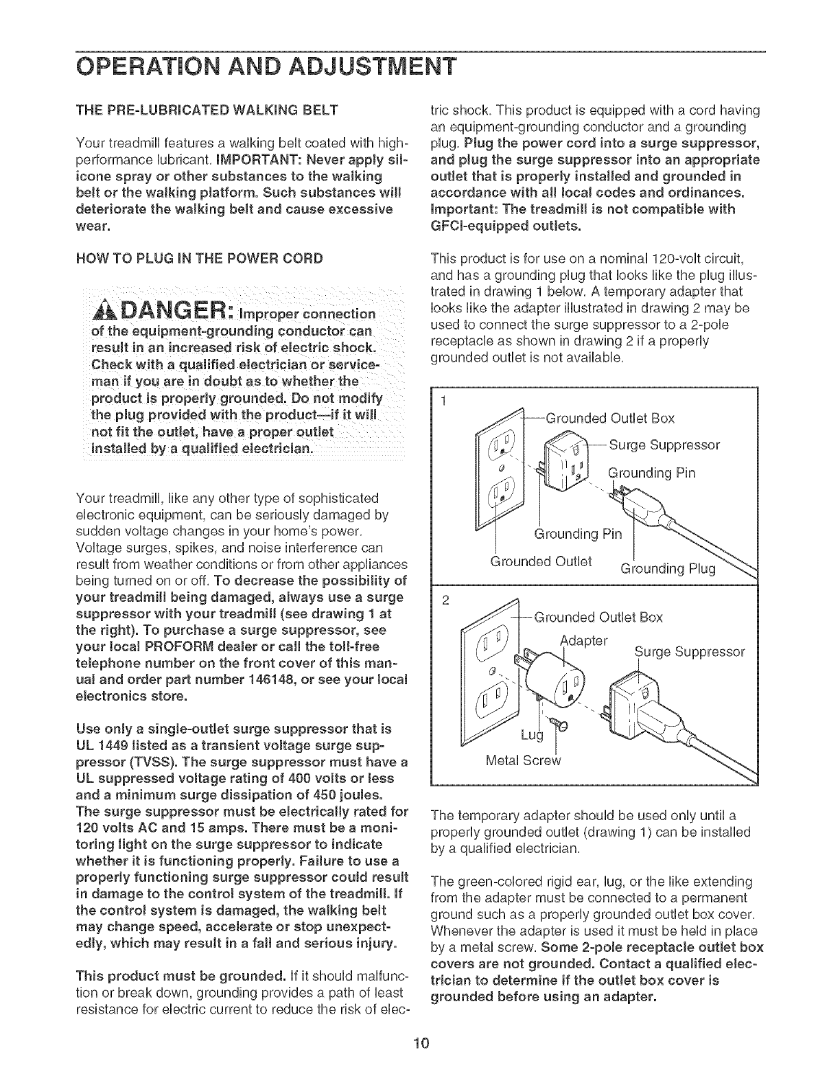
This product is for use on a nominal 120-volt circuit,
and has a grounding plug that looks like the plug illus-
trated in drawing 1 below. A temporary adapter that
looks like the adapter illustrated in drawing 2 may be
used to connect the surge suppressor to a 2-pole
receptacle as shown in drawing 2 if a properly
grounded outlet is not available,
I-Grounded Outlet Box
_'_-1 -- Surge Suppressor
_'< "-. Grounding Pin
Grounding Pin
_rounded Outlet Grounding Hug
2
_rounded Outlet Box
Adapter
Metal Screw_ . _Surge Suppressor
The temporary adapter should be used only until a
properly grounded outlet (drawing 1) can be installed
by a qualified electrician,
The green-colored rigid ear, lug, or the like extending
from the adapter must be connected to a permanent
ground such as a properly grounded outlet box cover.
Whenever the adapter is used it must be held in place
by a metal screw. Some 2-poJe receptacle outlet box
covers are not grounded. Contact a qualified elec-
trician to determine if the outJet box cover is
grounded before using an adapter.
10
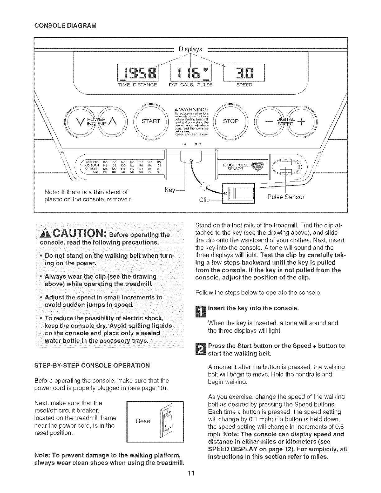
CONSOLE DmAGRAM
DispUays
TiME DISTANCE FAT CALS. PULSE SPEED
AVVARNING:
TO reduce dsk of sedous
injury, starld on foot r_l£
before star tiRg treadmill,
START read aJ'/d unde¢s_and the STOP
user's manual, aJlins#_Jc_
t_ons, and the warnings
before, use.
Keep cNdren Away.
U_ VO
145 188 130 125 118 110 -[OUCH PULSE
125 120 115 110 105 g5 90 SENSOR
20 80 40 50 60 70 80
Note: if there is a thin sheet of Key_ __
plastic on the console, remove it, Clip_:- _ Pulse Sensor
CAUTION: Beforeope,ot ngthe
console, read the following precautions.
o Do not stand on the walking belt when turn-
ing on the power.
o Always wear the clip (see the drawing
above) while operating the treadmill.
Adjust the speed in small increments to
avoid sudden jumps in speed.
oTo reduce the possibility of eJectdc shock,
keep the consoJe dry. Avoid spilling Jiquids
on the consoJe and place onJy a sealed
water bottJe in the accessory trays.
STEP-BY-STEP CONSOLE OPERATION
Before operating the console, make sure that the
power cord is properly plugged in (see page 10),
Next, make sure that the
reset/off circuit breaker,
located on the treadmill frame
near the power cord, is in the
reset position,
Reset
Note: To prevent damage to the waJking platform,
always wear clean shoes when using the treadmill.
11
Stand on the foot rails of the treadmill, Find the clip at-
tached to the key (see the drawing above), and slide
the clip onto the waistband of your clothes, Next, insert
the key into the console, A tone will sound and the
three displays will light, Test the clip by carefully tak-
ing a few steps backward until the key is pulled
from the consoJe, if the key is not pulled from the
consote, adjust the position of the clip.
Follow the steps below to operate the console,
Insert the key into the console.
When the key is inserted, a tone wiii sound and
the three displays wiii light,
Press the Start button or the Speed + button to
start the walking belt.
A moment after the button is pressed, the walking
belt will begin to move, Hold the handrails and
begin walking,
As you exercise, change the speed of the walking
belt as desired by pressing the Speed buttons,
Each time a button is pressed, the speed setting
will change by 0,1 mph; if a button is held down,
the speed setting will change in increments of 0,5
mph, Note: The consote can display speed and
distance in either miles or kilometers (see
SPEED DISPLAY on page 12). For simplicity, aH
instructions in this section refer to miles.
Tostopthewalkingbelt,presstheStopbutton,
Theelapsedtimewillbegintoflashinthe
Note:Duringthefirstfewminutesthatthetreadmill
isused,inspectthealignmentofthewalkingbelt,
andalignit ifnecessary(seepage17),
Changetheinclineof thetreadmillasdesired.
Tochangetheinclineofthetreadmill,presseither
oftheIncNnebuttonsuntilthedesiredinclinelevel
isreached,
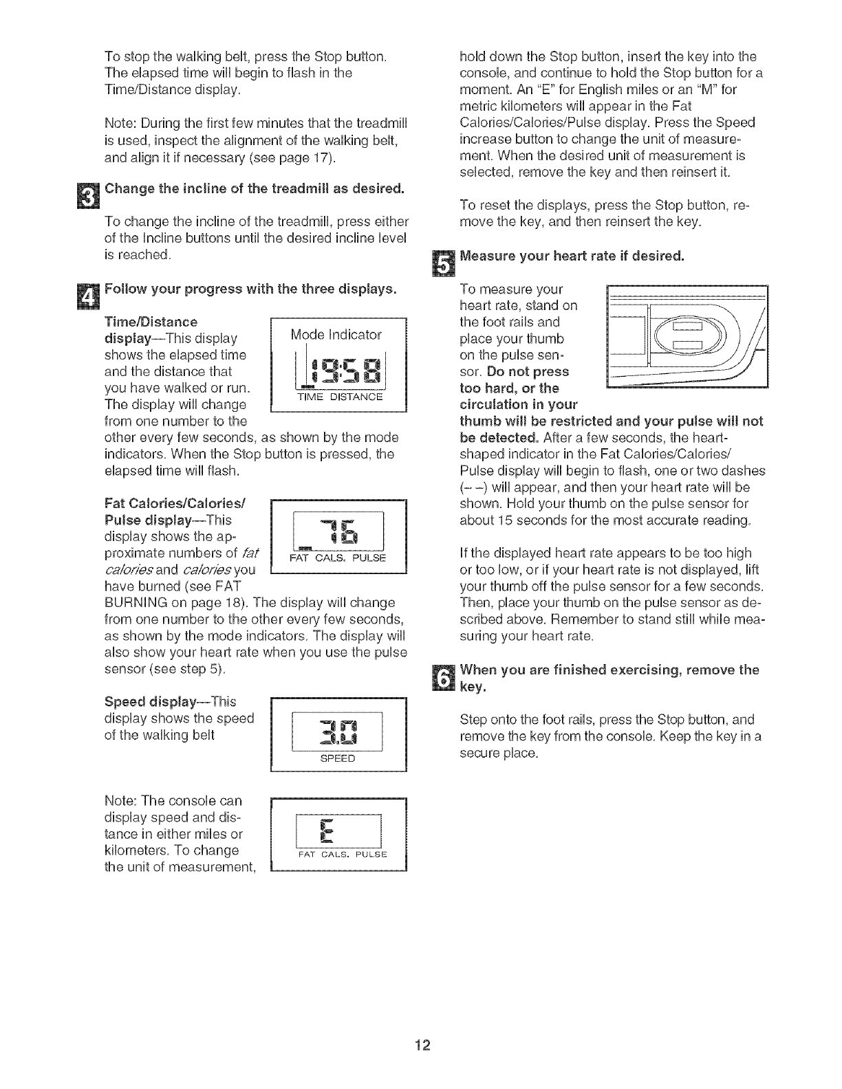
Followyourprogresswith thethreedisplays.
Time/Distance
display--Thisdisplay
showstheelapsedtime
andthedistancethat
youhavewalkedorrun,
Thedisplaywillchange
fromonenumbertothe
Modeindicator
TIME DISTANCE
other every few seconds, as shown by the mode
indicators, When the Stop button is pressed, the
elapsed time win flash,
Fat Calories/Calories/
Pulse dispJay--This _"1 _'_
display shows the ap: 11i£'_1t
proximate numbers of @/ FAT CALS. PULSE
calories and caiories you
have burned (see FAT
BURNING on page 18), The display will change
from one number to the other every few seconds,
as shown by the mode indicators, The display will
also show your heart rate when you use the pulse
sensor (see step 5),
Speed display--This
display shows the speed
of the walking belt
SPEED
hold down the Stop button, insert the key into the
console, and continue to hold the Stop button for a
moment, An "E" for English miles or an "M" for
metric kilometers will appear in the Fat
Calories/Calories/Pulse display, Press the Speed
increase button to change the unit of measure:
ment, When the desired unit of measurement is
selected, remove the key and then reinsert it,
To reset the displays, press the Stop button, re=
move the key, and then reinsert the key,
Measure your heart rate if desired.
To measure your
heart rate, stand on
the foot rails and
place your thumb
on the pulse sen°
sor, Do not press
too hard, or the
circulation in your
thumb will be restricted and your pulse wilt not
be detected. After a few seconds, the heart-
shaped indicator in the Fat Calories/Calories/
Pulse display will begin to flash, one or two dashes
(- -) will appear, and then your heart rate will be
shown, Hold your thumb on the pulse sensor for
about 15 seconds for the most accurate reading,
If the displayed heart rate appears to be too high
or too low, or if your heart rate is not displayed, lift
your thumb off the pulse sensor for a few seconds,
Then, place your thumb on the pulse sensor as de:
scribed above, Remember to stand still while mea:
suring your heart rate,
When you are finished exercising, remove the
key.
Step onto the foot rails, press the Stop button, and
remove the key from the console, Keep the key in a
secure place,
Note: The console can
display speed and dis:
tance in either miles or
kilometers, To change
the unit of measurement,
[
FAT CALS. PULSE
12
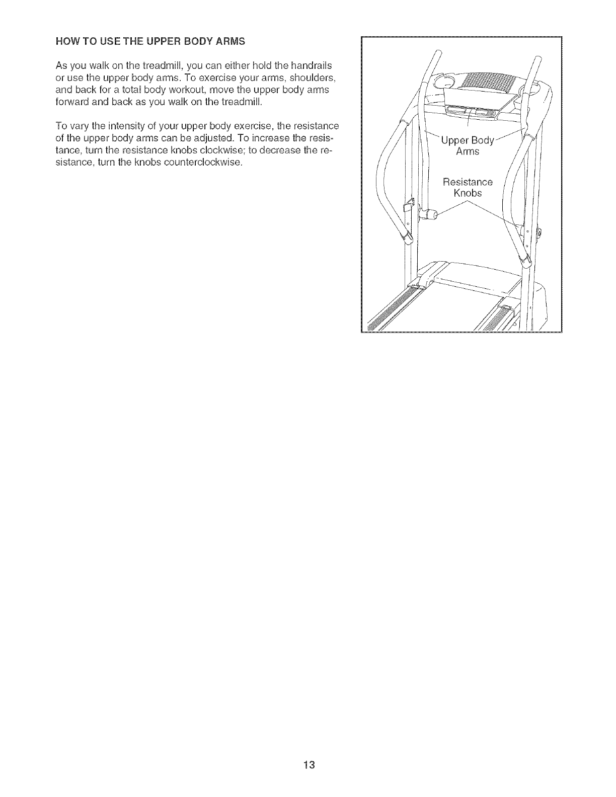
HOW TO USE THE UPPER BODY ARMS
As you waUkon the treadmHU,you can either hoUdthe handrails
or use the upper body arms, To exercise your arms, shouUders,
and back for a totaUbody workout, move the upper body arms
forward and back as you waUkon the treadmill
To vary the intensity of your upper body exercise, the resistance
of the upper body arms can be adjusted, To increase the resis-
tance, turn the resistance knobs cUockwise; to decrease the re-
sistance, turn the knobs counterclockwise,
13
HOW TO FOLD AND MOVE THE TREADMILL
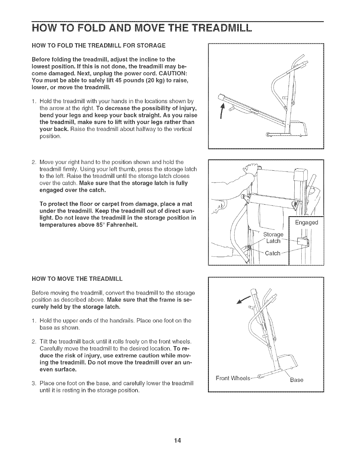
HOW TO FOLD THE TREADMILL FOR STORAGE
Before folding the treadmill, adjust the incline to the
towest position. If this is not done, the treadmill may be-
come damaged. Next, unptug the power cord. CAUTION:
You must be able to safely tift 45 pounds (20 kg) to raise,
tower, or move the treadmill.
HoUdthe treadmHUwith your hands in the Uocations shown by
the arrow at the right, To decrease the possibility of injury,
bend your tegs and keep your back straight. As you raise
the treadmill, make sure to lift with your tegs rather than
your back. Raise the treadmill about halfway to the vertical
position,
2, Move your right hand to the position shown and hold the
treadmill firmly, Using your left thumb, press the storage latch
to the left, Raise the treadmill until the storage latch closes
over the catch, Make sure that the storage tatch is fatty
engaged over the catch.
To protect the floor or carpet from damage, place a mat
under the treadmill Keep the treadmill out of direct sun-
tight. Do not leave the treadmill in the storage position in
temperatures above 85 ° Fahrenheit. Engaged
HOW TO MOVE THE TREADMILL
Before moving the treadmill, convert the treadmill to the storage
position as described above, Make sure that the frame is se-
curely held by the storage tatch.
1, Hold the upper ends of the handrails, Place one foot on the
base as shown,
2, Tilt the treadmill back until it rolls freely on the front wheels,
Carefully move the treadmill to the desired location, To re-
dace the risk of injury, use extreme caution while mov-
ing the treadmill. Do not move the treadmill over an un-
even surface.
3, Place one foot on the base, and carefully lower the treadmill
until it is resting in the storage position,
Front Wheels \Base
14
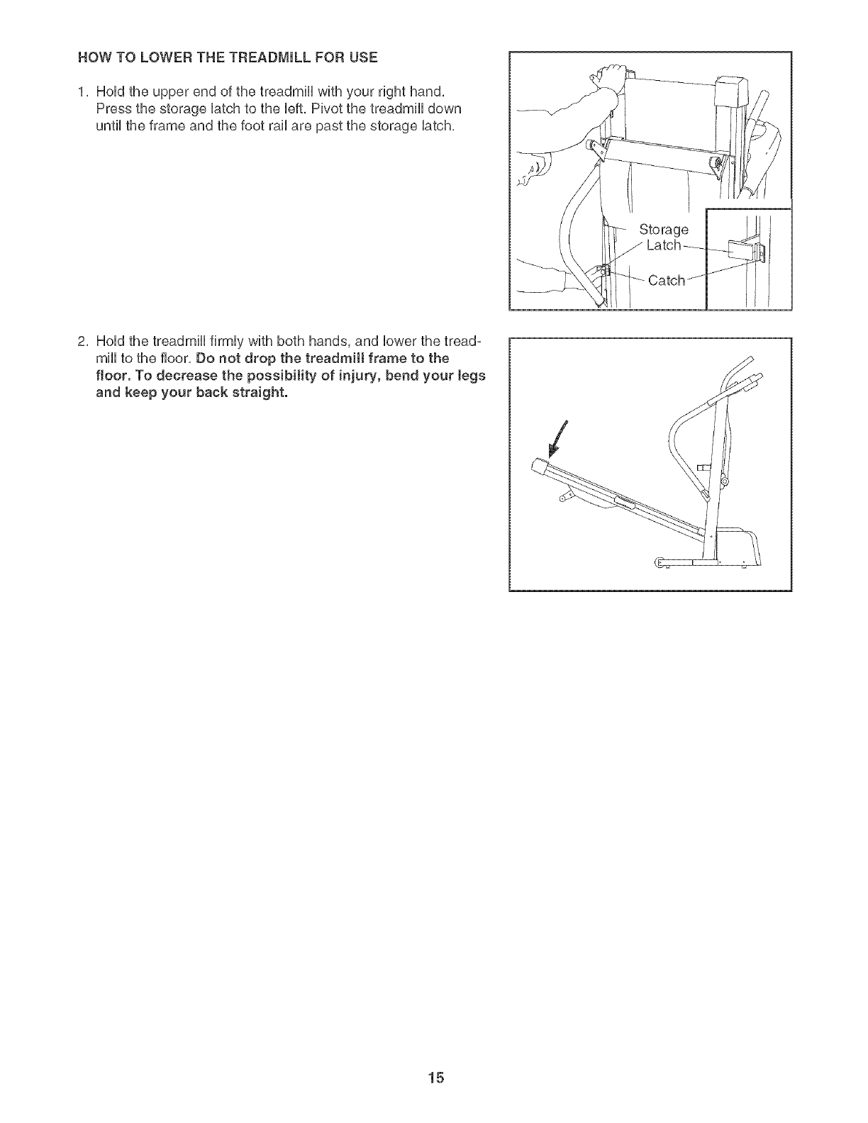
HOW TO LOWER THE TREADMmLL FOR USE
1, HoHdthe upper end of the treadmHHwith your right hand,
Press the storage Hatchto the Heft,Pivot the treadmHHdown
until the frame and the foot rail are past the storage Hatch,
Storage
Latch
HI
2, HoHdthe treadmHHfirmHywith both hands, and Howerthe tread°
mHHto the floor, Do not drop the treadmill frame to the
floor. To decrease the possibility of injury, bend your tegs
and keep your back straight.
15
TROUBLESHOOTING
Most treadmill problems can be solved by following the steps below. Find the symptom that applies, and
follow the steps listed, mffurther assistance is needed, please call the totFfree telephone number on the
front cover of tMs manual.
PROBLEM: The power does not turn on
SOLUTmON: a, Make sure that the power cord is plugged into a surge suppressor, and that the surge suppressor
is plugged into a properly grounded outlet (see page 10). Use only a single-outlet surge suppres-
sor that meets all of the specifications described on page 10. important: The treadmill is not com-
patible with GFCI-equipped outlets.
b. After the power cord has been plugged in, make sure that the key is fully inserted into the console.
C, Check the reset/off circuit breaker located on the
treadmill frame near the power cord. if the switch
protrudes as shown, the circuit breaker has tripped.
To reset the circuit breaker, wait for five minutes
and then press the switch back in. Tripped Reset
PROBLEM: The power turns off during use
SOLUTION: a. Check the circuit breaker located on the treadmill frame near the power cord (see the drawing
above), if the circuit breaker has tripped, wait for five minutes and then press the switch back in.
b. Make sure that the power cord is plugged in. if the power cord is plugged in, unplug it, wait for
five minutes, and then plug it back in.
c, Remove the key from the console, Rsinsert the key fully into the console,
d. if the treadmill still will not run, call the telephone number on the front cover of this manual.
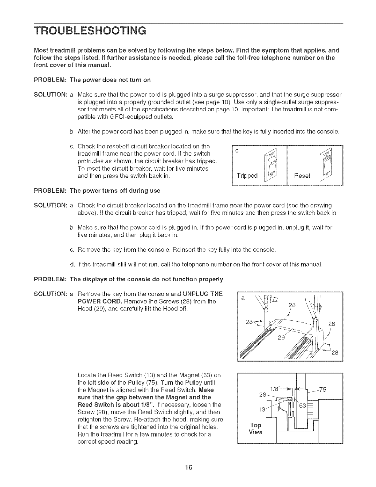
PROBLEM: The displays of the console do not function properly
SOLUTION: a, Remove the key from the console and UNPLUG THE
POWER CORD. Remove the Screws (28) from the
Hood (29), and carefully lift the Hood off,
29
28
},
/--_e
Locate the Reed Switch (13) and the Magnet (63) on
the left side of the Pulley (75), Turn the Pulley until
the Magnet is aligned with the Reed Switch, Make
sure that the gap between the Magnet and the
Reed Switch is about 1/8". if necessary, loosen the
Screw (28), move the Reed Switch slightly, and then
retighten the Screw, Re-attach the hood, making sure
that the screws are tightened into the original hobs,
Run the treadmill for a few minutes to check for a
correct speed reading,
View
16
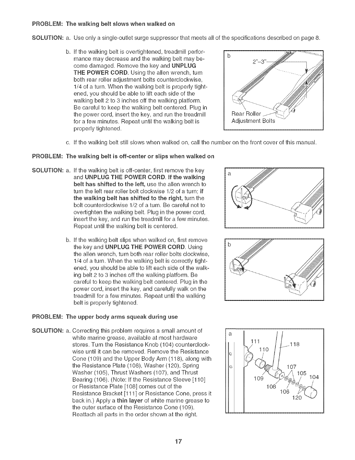
PROBLEM: The walking belt slows when waJked on
SOLUTION: a, Use only a single-outlet surge suppressor that meets all of the specifications described on page 8,
b, if the walking belt is overtightened, treadmill perfor-
mance may decrease and the walking belt may be-
come damaged, Remove the key and UNPLUG
THE POWER CORD, Using the allen wrench, turn
both rear roller adjustment bolts counterclockwise,
1/4 of a turn, When the walking belt is properly tight-
ened, you should be able to lift each side of the
walking belt 2 to 3 inches off the walking platform,
Be careful to keep the walking belt centered, Hug in
the power cord, insert the key, and run the treadmill
for a few minutes, Repeat until the walking belt is
properly tightened,
Rear Roller
Adjustment Bolts
c, if the walking belt still slows when walked on, call the number on the front cover of this manual,
PROBLEM: The walking belt is off-center or slips when walked on
SOLUTmON: a, if the walking belt is off-center, first remove the key
and UNPLUG THE POWER CORD, If the walking
belt has shifted to the left, use the allen wrench to
turn the left rear roller bolt clockwise 1/2 of a turn; if
the walking belt has shifted to the right, turn the
bolt counterclockwise 1/2 of a turn, Be careful not to
overtighten the walking belt, Hug in the power cord,
insert the key, and run the treadmill for a few minutes,
Repeat until the walking belt is centered,
b, if the walking belt slips when walked on, first remove
the key and UNPLUG THE POWER CORD, Using
the allen wrench, turn both rear roller bolts clockwise,
1/4 of a turn, When the walking belt is correctly tight-
ened, you should be able to lift each side of the walk-
ing belt 2 to 3 inches off the walking platform, Be
careful to keep the walking belt centered, Hug in the
power cord, insert the key, and carefully walk on the
treadmill for a few minutes, Repeat until the walking
belt is properly tightened,
PROBLEM: The upper body arms squeak during use
SOLUTmON: a, Correcting this problem requires a small amount of
white marine grease, available at most hardware
stores, Turn the Resistance Knob (104) counterclock-
wise until it can be removed, Remove the Resistance
Cone (109) and the Upper Body Arm (118), along with
the Resistance Hate (108), Washer (120), Spring
Washer (105), Thrust Washers (107), and Thrust
Bearing (106), (Note: if the Resistance Sleeve [110]
or Resistance Hate 1108] comes out of the
Resistance Bracket 1111] or Resistance Cone, press it
back in,) Apply a thin tayer of white marine grease to
the outer surface of the Resistance Cone (109),
Reattach all parts in the order shown at the right,
111
110
107
109 ./
1O8 106 120
104
17
CONDiTiONiNG GUJDEUNES
WARNJNG: BeforebeginningtHs
or any exercise program, consult your physi°
cian. This is especially important for individu-
als over the age of 35 or individuals with pre-
existing health problems.
The pulse sensor is not a medical device.
Various factors, including your movement,
may affect the accuracy of heart rate readings.
The sensor is intended onty as an exercise aid
in determining heart rate trends in general
The following guidelines wiii help you to plan your ex=
ercise program, For more detailed exercise informa=
tion, obtain a reputable book or consult your physician,
EXERCISE iNTENSiTY
Whether your goal is to burn fat or to strengthen your
cardiovascular system, the key to achieving the
desired results is to exercise with the proper intensity,
The proper intensity level can be found by using your
heart rate as a guide, The chart below shows recom-
mended heart rates for fat burning and aerobic exercise,
HEART RATE TRAmNBNG ZONES
AEROBIC 165 155 t45 140 130 125 115
MAX FAT BURN 145 138 t30 125 118 110 103
FAT BURN 125 120 115 110 105 95 90
Age 20 30 40 50 60 70 80
To find the proper heart rate for you, first find your age
near the bottom of the chart (ages are rounded off to
the nearest ten years), Next, find the three numbers
above your age, The three numbers define your "train-
ing zone," The lower two numbers are recommended
heart rates for fat burning; the higher number is the
recommended heart rate for aerobic exercise,
To measure your heart rate during exercise, use the
pulse sensor,
Fat Burning
To burn fat effectively, you must exercise at a relatively
low intensity level for a sustained period of time,
During the first few minutes of exercise, your body
uses easily accessible o3,@ohyd/_te o31briesfor en:
ergy, Only after the first few minutes does your body
begin to use stored @tc,-s/briesfor energy, if your goal
is to burn fat, adjust the speed and incline of the tread-
mill until your heart rate is near the lowest number in
your training zone,
For maximum fat burning, adjust the speed and incline
of the treadmill until your heart rate is near the middle
number in your training zone,
Aerobic Exercise
if your goal is to strengthen your cardiovascular sys-
tem, your exercise must be "aerobic," Aerobic exercise
is activity that requires large amounts of oxygen for
prolonged periods of time, This increases the demand
on the heart to pump blood to the muscles, and on the
lungs to oxygenate the blood, For aerobic exercise,
adjust the speed and incline of the treadmill until your
heart rate is near the highest number in your training
zone,
WORKOUT GUIDELINES
Each workout should include the following three parts:
A Warm-up--Start each workout with 5 to 10 minutes
of stretching and light exercise, A proper warm-up in-
creases your body temperature, heart rate and circula-
tion in preparation for exercise,
Training Zone Exercise--After warming up, increase
the intensity of your exercise until your pulse is in your
training zone for 20 to 60 minutes, (During the first few
weeks of your exercise program, do not keep your
pulse in your training zone for longer than 20 minutes,)
Breathe regularly and deeply as you exercise--never
hold your breath,
A CooFdown--Finish each workout with 5 to 10 min-
utes of stretching to cool down, This will increase the
flexibility of your muscles and will help prevent post-
exercise problems,
EXERCISE FREQUENCY
To maintain or improve your condition, complete three
workouts each week, with at bast one day of rest be-
tween workouts, After a few months, you may com-
plete up to five workouts each week if desired, The key
to success is to make exercise a regular and enjoyable
part of your everyday life,
18
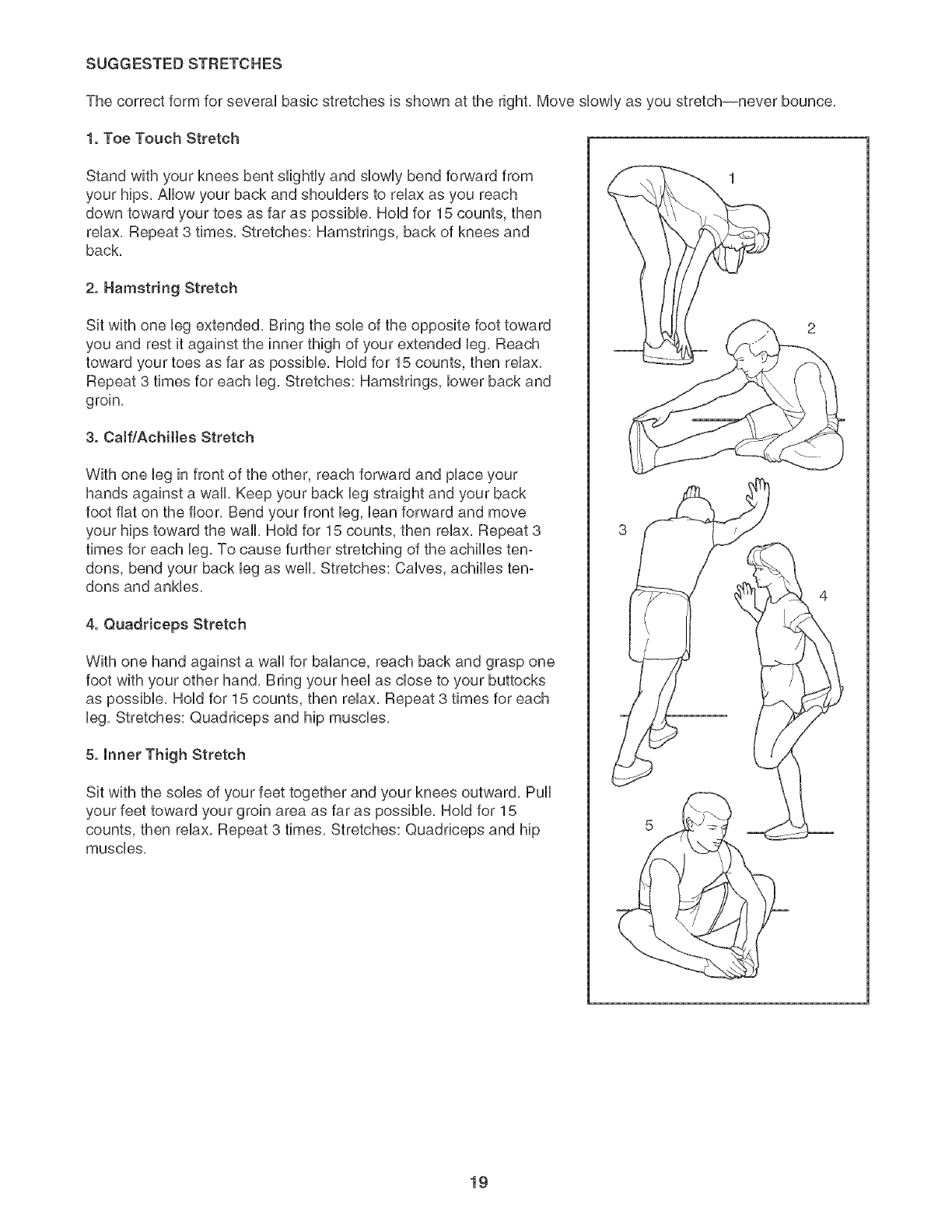
SUGGESTED STRETCHES
The correct form for several basic stretches is shown at the right, Move slowly as you stretch--never bounce,
1. Toe Touch Stretch
Stand with your knees bent slightly and slowly bend forward from
your hips, Allow your back and shoulders to relax as you reach
down toward your toes as far as possible, Hold for 15 counts, then
relax, Repeat 3 times, Stretches: Hamstrings, back of knees and
back,
2. Hamstring Stretch
Sit with one leg extended, Bring the sob of the opposite foot toward
you and rest it against the inner thigh of your extended leg, Reach
toward your toes as far as possible, Hold for 15 counts, then relax,
Repeat 3 times for each leg, Stretches: Hamstrings, lower back and
groin,
3. Caff/Achiltes Stretch
With one leg in front of the other, reach forward and place your
hands against a wall, Keep your back leg straight and your back
foot fiat on the floor, Bend your front leg, ban forward and move
your hips toward the wall, Hold for 15 counts, then relax, Repeat 3
times for each leg, To cause further stretching of the achilles ten-
dons, bend your back leg as well, Stretches: Calves, achilles ten-
dons and ankles,
4. Quaddceps Stretch
With one hand against a wall for balance, reach back and grasp one
foot with your other hand, Bring your heel as dose to your buttocks
as possible, Hold for 15 counts, then relax, Repeat 3 times for each
leg, Stretches: Quadrieeps and hip muscles,
5. Inner Thigh Stretch
Sit with the sobs of your feet together and your knees outward, Pull
your feet toward your groin area as far as possible, Hold for 15
counts, then relax, Repeat 3 times, Stretches: Quadriceps and hip
muscles,
19
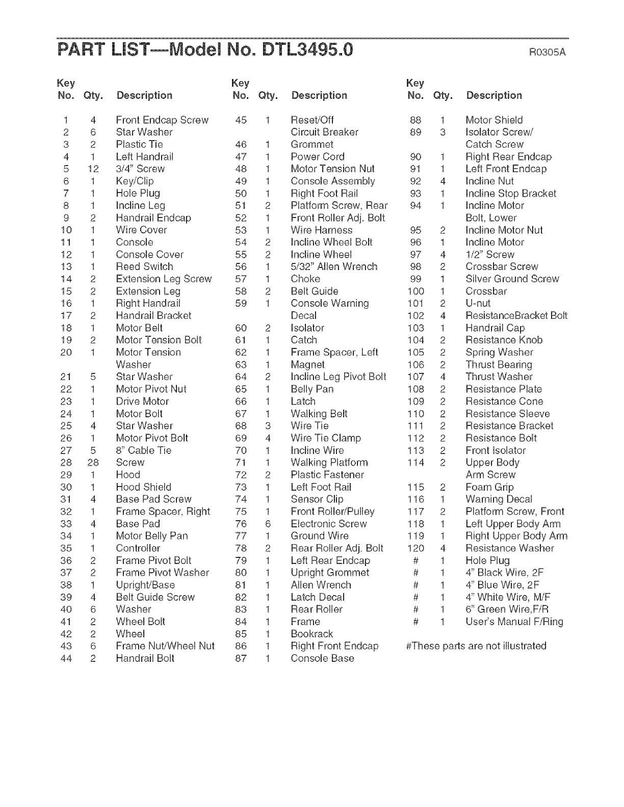
PART LiST--Model No. DTL3495.0 RO3OSA
Key Key Key
No. Qty. Description No. Qty. Description No. Qty. Description
1 4 Front Endcap Screw 45 1 Reset/Off 88 1
2 6 Star Washer Circuit Breaker 89 3
3 2 Plastic Tie 46 1 Grommet
4 1 Left Handrail 47 1 Power Cord 90 1
5 12 3/4" Screw 48 1 Motor Tension Nut 91 1
6 1 Key/Clip 49 1 Console Assembly 92 4
7 1 Hob Hug 50 1 Right Foot Rail 93 1
8 1 Incline Leg 51 2 Platform Screw, Rear 94 1
9 2 Handrail Endcap 52 1 Front Roller Adj, Bolt
10 1 Wire Cover 53 1 Wire Harness 95 2
11 1 Console 54 2 Incline Wheel Bolt 96 1
12 1 Console Cover 55 2 Incline Wheel 97 4
13 1 Reed Switch 56 1 5/32" Allen Wrench 98 2
14 2 Extension Leg Screw 57 1 Choke 99 1
15 2 Extension Leg 58 2 Belt Guide 100 1
16 1 Right Handrail 59 1 Console Warning 101 2
17 2 Handrail Bracket Decal 102 4
18 1 Motor Belt 60 2 Isolator 103 1
19 2 Motor Tension Bolt 61 1 Catch 104 2
20 1 Motor Tension 62 1 Frame Spacer, Left 105 2
Washer 63 1 Magnet 106 2
21 5 Star Washer 64 2 Incline Leg Pivot Bolt 107 4
22 1 Motor Pivot Nut 65 1 Belly Pan 108 2
23 1 Drive Motor 66 1 Latch 109 2
24 1 Motor Bolt 67 1 Walking Belt 110 2
25 4 Star Washer 68 3 Wire Tie 111 2
26 1 Motor Pivot Bolt 69 4 Wire Tie Clamp 112 2
27 5 8" Cable Tie 70 1 Incline Wire 113 2
28 28 Screw 71 1 Walking Platform 114 2
29 1 Hood 72 2 Plastic Fastener
30 1 Hood Shield 73 1 Left Foot Rail 115 2
31 4 Base Pad Screw 74 1 Sensor Clip 116 1
32 1 Frame Spacer, Right 75 1 Front Roller/Pulley 117 2
33 4 Base Pad 76 6 Electronic Screw 118 1
34 1 Motor Belly Pan 77 1 Ground Wire 119 1
35 1 Controller 78 2 Rear Roller Adj, Bolt 120 4
36 2 Frame Pivot Bolt 79 1 Left Rear Endcap # 1
37 2 Frame Pivot Washer 80 1 Upright Grommet # 1
38 1 Upright/Base 81 1 Allen Wrench # 1
39 4 Belt Guide Screw 82 1 Latch Decal # 1
40 6 Washer 83 1 Rear Roller # 1
41 2 Wheel Bolt 84 1 Frame # 1
42 2 Wheel 85 1 Bookrack
43 6 Frame Nut/Wheel Nut 86 1 Right Front Endcap
44 2 Handrail Bolt 87 1 Console Base
Motor Shield
Isolator Screw/
Catch Screw
Right Rear Endcap
Left Front Endcap
Incline Nut
Incline Stop Bracket
Incline Motor
Bolt, Lower
Incline Motor Nut
Incline Motor
1/2" Screw
Crossbar Screw
Silver Ground Screw
Crossbar
U-nut
ResistanceBracket Bolt
Handrail Cap
Resistance Knob
Spring Washer
Thrust Washer
Resistance Hate
Resistance Cone
Resistance Sleeve
Resistance Bracket
Resistance Bolt
Front Isolator
Upper Body
Arm Screw
Foam Grip
Warning Decal
Platform Screw, Front
Right Upper Body Arm
Resistance Washer
Hob Hug
4" Black Wire, 2F
4" Blue Wire, 2F
4" White Wire, M/F
6" Green Wire,F/R
User's Manual F/Ring
#These parts are not illustrated
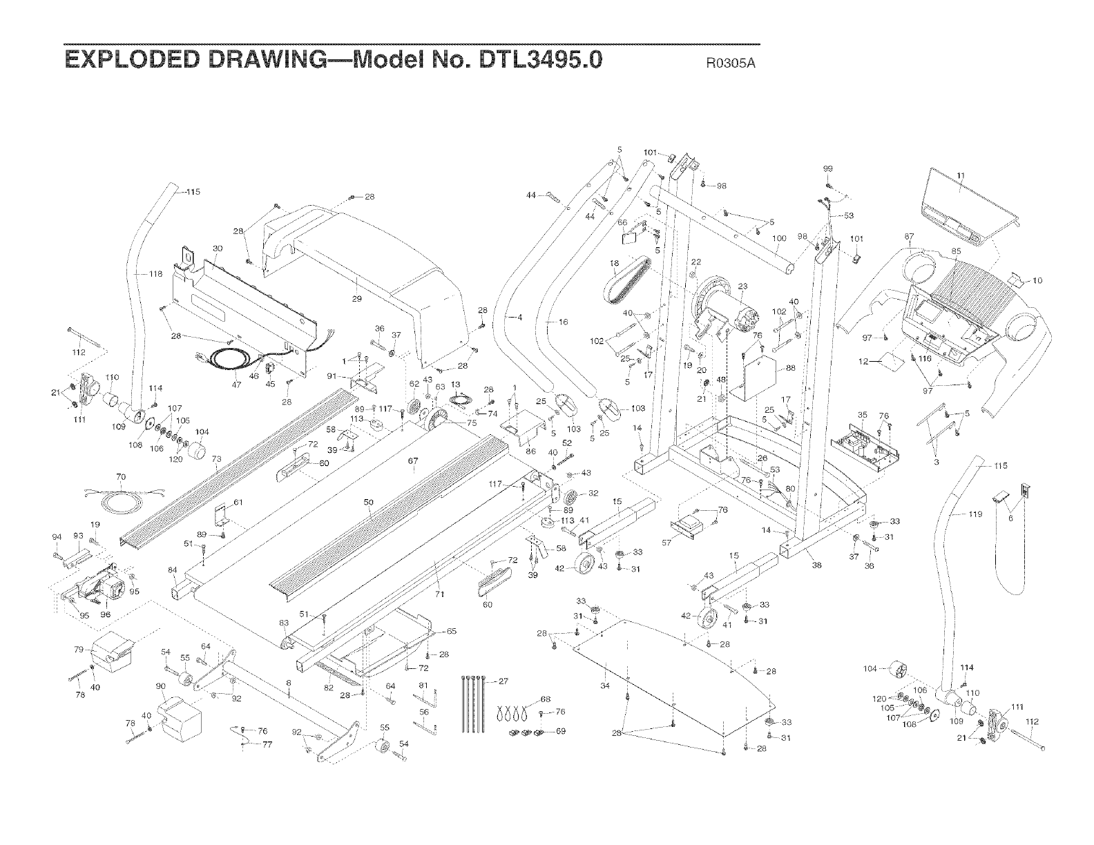
EXPLODED DRAWmNG--ModeM No. DTL3495.0 Ro3osA
21<
112
/
//
I 118
",,,
i! 28 ......
i_ i¸
30
lo7
105
104
108 106
120 73
70
46
45
28
54
, 55
40 90
78
40
78
51
83
64 81
56
55
54
5 101 ....
/
/
/
/ /
,/
,, 28 4
//
28
16
5
18
40 _
102
72
'_ 98
48
2"
1 O0
9
23
4o
88
25
60
42
28
97
35 76
"41),
@ g s-
37
38 _6
104
b-
87
97
_ 5 "%
11.5
119 6
21

ORDERmNG REPLACEMENT PARTS
To order replacement parts, see the front cover of this manual. To help us assist you, please be prepared to give
the following information:
The MODEL NUMBER of the product (DTL3495.0
The NAME of the product (PROFORM CROSSWALK 365e treadmill)
The SERIAL NUMBER of the product (see the front cover of this manual)
The KEY NUMBER and DESCRiPTiON of the part(s) (see the PART LiST and the EXPLODED DRAWING in
the center of this manual)
LiMiTED WARRANTY
iCON Health & Fitness, Inc. (iCON), warrants this product to be free from defects in workmanship and
material, under normal use and service conditions. The drive motor is warranted for three (3) years after
the date of purchase. The parts and labor are warranted for ninety (90) days after the date of purchase.
This warranty extends only to the original purchaser, iCON's obligation under this warranty is limited to
replacing or repairing, at iCON's option, the product through one of its authorized service centers. All re-
pairs for which warranty claims are made must be pre-authorized by iCON. if the product is shipped to a
service center, freight charges to and from the service center will be the customer's responsibility. For in-
home service, the customer will be responsible for a minimal trip charge. This warranty does not extend
to any product or damage to a product caused by or attributable to freight damage, abuse, misuse, im-
proper or abnormal usage or repairs not provided by an iCON authorized service center; to products
used for commercial or rental purposes; or to products used as store display models. No other warranty
beyond that specifically set forth above is authorized by iCON.
iCON is not responsible or liable for indirect, special or consequential damages arising out of or in con-
nection with the use or performance of the product or damages with respect to any economic loss, loss
of property, loss of revenues or profits, loss of enjoyment or use, costs of removal or installation or other
consequential damages of whatsoever nature. Some states do not allow the exclusion or limitation of in-
cidental or consequential damages. Accordingly, the above limitation may not apply to you.
The warranty extended hereunder is in lieu of any and all other warranties and any implied warranties of
merchantability or fitness for a particular purpose is limited in its scope and duration to the terms set
forth herein. Some states do not allow limitations on how long an implied warranty lasts. Accordingly, the
above limitation may not apply to you.
This warranty gives you specific legal rights. You may also have other rights which vary from state to state.
iCON HEALTH & FITNESS, iNC., 1500 S. 1000 W., LOGAN, UT 84321-9813
Part No. 224902 RO305A Printed in USA © 2005 iCON IP, Inc.
