PUREEZ Water Dispenser Manual L0712457
User Manual: PUREEZ PUREEZ Water Dispenser Manual PUREEZ Water Dispenser Owner's Manual, PUREEZ Water Dispenser installation guides
Open the PDF directly: View PDF ![]() .
.
Page Count: 28
OPERATION MANUAL
Dear Customers!
We would like to congratulate you on your decision to join the Tana Water family by
purchasing T-6 - the world's most advanced water bar of its type.
T-6 comes to your home after years of research and development, and after passing
through the hands of some of the best designers in the world.
The filtration and purification system used on T-6 an international patent, ensuring a
stellar drinking experience for the entire family by providing the choice of unlimited hot
or cold water, sparklingly clear, refreshing and healthy.
Tana Water is one of the worlds largest and most experienced company specializing in
the production, development, service and marketing of drinking-water filtration and
purification systems. Tana Water's computerized service system is among the most
advanced in the market, providing our clients with generous and professional service.
Sincerely,
Tana Water
Manufacturer's Certificate of Compliance
Tana Water Company hereby confirms that the T-6 appliance manufactured by Tana Water
complies with the requirements of Standard no. 1505 for Water Quality and with the requirements
of Standard: CE, UL and International standards.
All electrical components and materials used in the manufacture of these dispensers comply with
international standards for use in a food /drinking water environment. The dispenser's chemical
purification process absorbs chlorine (Class I, at least 75%), and provides Class B microbe
purification against volatile organic compounds (VOCs).
Tana Water and its quality assurance system have been certified according to the international
standard ISO 9001:2000.
Avinoam Kfir
Quality Director
Operation Manual T6 Page: 2
Date: May 2005
CONTENTS:
.1GENERAL VIEW ............................................................................................................................... 4
.2TECHNICAL FEATURES .............................................................................................................. 5
.3OPERATION PANEL ....................................................................................................................... 6
.4INSTALLATION ............................................................................................................................... 7
4.1 GENERAL INSTRUCTIONS ............................................................................................................... 7
4.2WATER SOURCE CONNECTION ...................................................................................................... 7
4.3PREPARATION FOR OPERATION ..................................................................................................... 7
.5OPERATION ....................................................................................................................................... 9
5. IWATER DISPENSING ........................................................................................................................ 9
5.2SYSTEM MODES .............................................................................................................................. 10
5.3MENU FUNCTION ............................................................................................................................ 11
.6MAINTENANCE AND REPLACEMENT ............................................................................. 16
6.1 DROP COLLECTOR EMPTYING ..................................................................................................... 16
6.2REPLACEMENT ............................................................................................................................... 16
6.3COUNTERS DISPLAY ..................................................................................................................... 16
6.4FILTER REPLACEMENT ................................................................................................................. 17
6 .SUV LAMP REPLACEMENT ............................................................................................................ 17
.7CLEANING THE APPLIANCE ................................................................................................. 18
.8WEEKENDS /HOLIDAYS /VACATIONS .......................................................................... 18
.9WARNING * SAFETY * SERVICE ......................................................................................... 18
.loTROUBLESHOOTING ................................................................................................................ 20
1o. 1CUSTOMER .................................................................................................................................... 20
10.2TECHNICIAN .................................................................................................................................. 21
.11ELECTRIC DIAGRAM ............................................................................................................... 24
12PARTS LIST ...................................................................................................................................... 25
12.1 EXPLODED VIEW .......................................................................................................................... 25
12.2PARTS CATALOGUE ..................................................................................................................... 27
Operation Manual T6 Page: 3
Date: May 2005
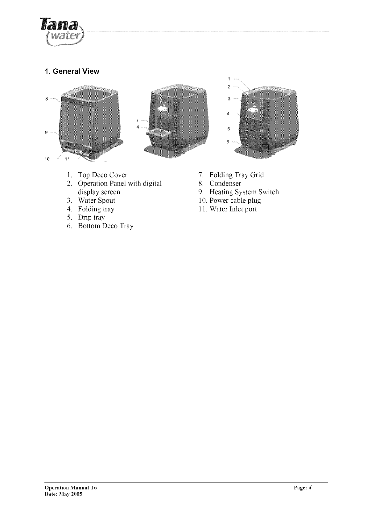
1. General View
1. Top Deco Cover
2. Operation Panel with digital
display screen
3. Water Spout
4. Folding tray
5. Drip tray
6. BottomDeco Tray
7. Folding Tray Grid
8. Condenser
9. Heating System Switch
10. Power cable plug
11. Water Inlet port
Operation Manual T6 Page: 4/
Date: May 2005
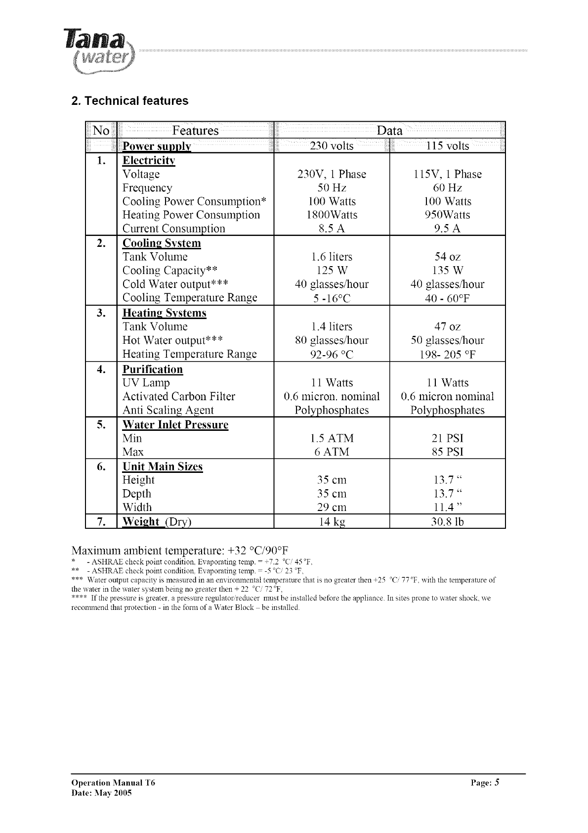
2. Technical features
Data
Power supply ; 230 volts .115 volts
1. Electricity
Voltage 230V, 1 Phase 115V, 1 Phase
Frequency 50 Hz 60 Hz
Cooling Power Consumption* 100 Watts 100 Watts
Heating Power Consumption 1800Watts 950Watts
Current Consumption 8.5 A 9.5 A
2. CoolinR System
Tank Volume 1.6 liters 54 oz
Cooling Capacity** 125 W 135 W
Cold Water output*** 40 glasses/hour 40 glasses/hour
Cooling Temperature Range 5 -16°C 40 - 60°F
3. Heatin_ Systems
Tank Volume 1.4 liters 47 oz
Hot Water output*** 80 glasses/hour 50 glasses/hour
Heating Temperature Range 92-96 °C 198- 205 °F
4. Purification
UV Lamp 11 Watts 11 Watts
Activated Carbon Filter 0.6 micron, nominal 0.6 micron nominal
Anti Scaling Agent Polyphosphates Polyphosphates
5. Water Inlet Pressure
Min 1.5 ATM 21 PSI
Max 6 ATM 85 PSI
6. Unit Main Sizes
Height 35 cm 13.7"
Depth 35 cm 13.7"
Width 29 cm 11.4"
7. Weight (Dry) 14 kg 30.8 lb
Maximum ambient temperature: +32 °C/90°F (4_ F.
* - ASHRAE check point condition, Ex aporating temp. = +7.2 .... _,_,
** - ASHRAE check point condition. Evaporating temp. = -5 23 °F,
*** Water output capacity is measured in an em ironmental temperature that is no greater then +25 °C 77 °F. with the temperature of
the water in the water system being no greater then + 22 °C 72 °F.
**** If the pressure is greater, a pressure regulator reducer must be installed before the appliance. In sites prone to water shock, we
recommend that protection - in the fore1 of a Water Block be installed.
Operation Manual T6 Page: 5
Date: May 2005

3. Operation panel
\
J--8
/
2
3
4
5
6
7
9
10
11
12
13
14
15
"MIX"
"HOT"
"EH"
DISPLY
"MENU/
OK"
"BACK"
"COLD"
"CUP"
HOT
WATER
TEMP.
"vapor"
symbol
"clock"
symbol
UV
"key"
symbol
"snow"
symbol
COLD
WATER
TEMP.
Mixed water dispensing key
(Predefined dosage ant temperature)
Hot water dispensing key
Extra Hot Key
Graphic Display
Enter Menu Functions & OK key
Back key (return to previous menu)
Cold water dispensing key
Scroll up at menu functions
Predefined dosage and temperature water
dispensing key
Scroll down at menu functions
Hot water temperature indication bar
Heating system operation indication
Alight when heater ON
Timer function indication
Appears when automatic energy saving mode ON
UV system indication
Child protection indication
Appears when child protection mode ON
Cooling system operation indication
Alight when compressor ON
Cold water temperature indication bar
Operation Manual T6 Page: 6
Date: May 2005
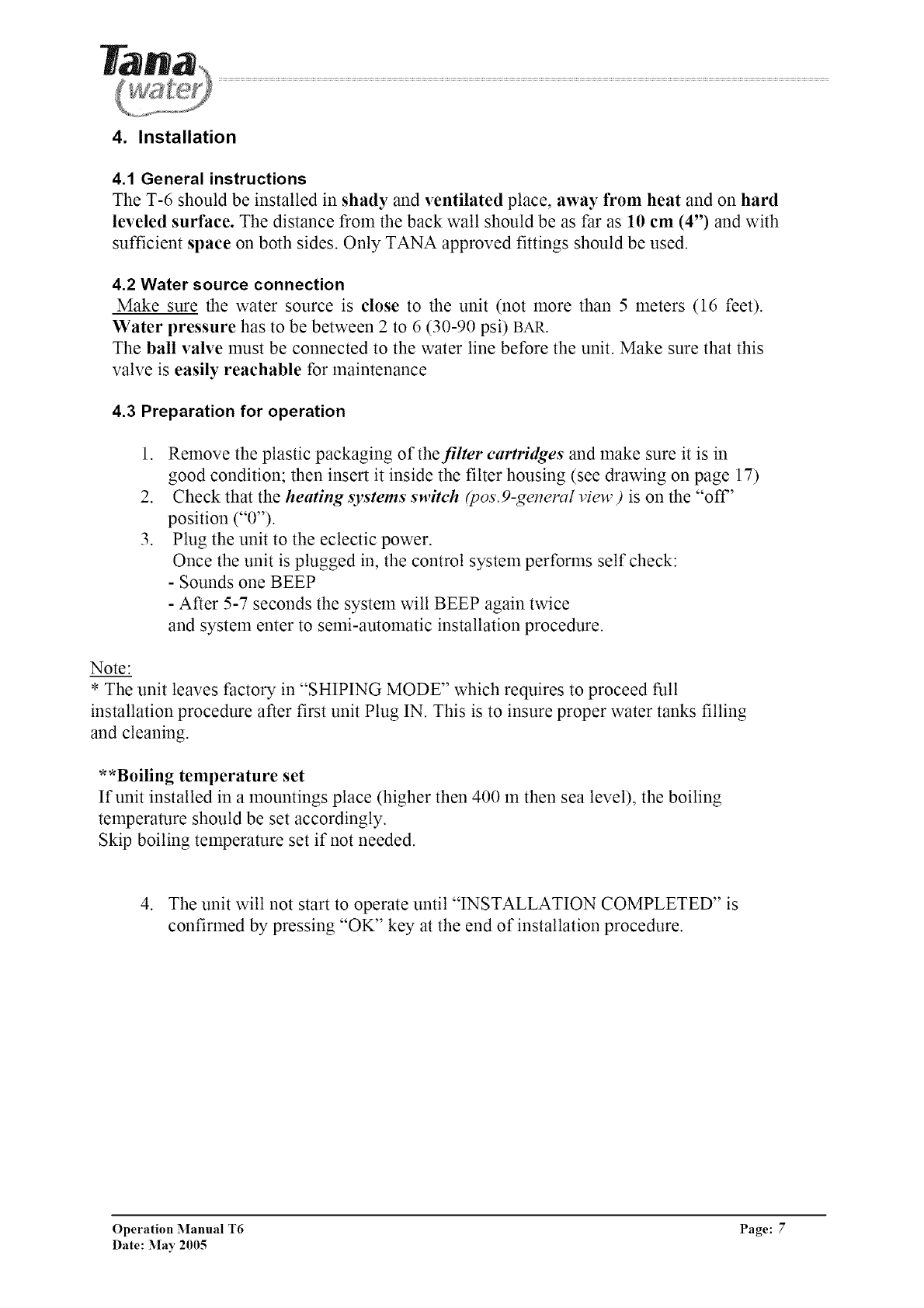
4. Installation
4.1 General instructions
The T-6 should be installed in shady and ventilated place, away from heat and on hard
leveled surface. The distance from the back wall should be as far as 10 cm (4") and with
sufficient space on both sides. Only TANA approved fittings should be used.
4.2 Water source connection
Make sure the water source is close to the unit (not more than 5 meters (16 feet).
Water pressure has to be between 2to 6 (30-90 psi) BAR.
The ball valve must be connected to the water line before the unit. Make sure that this
valve is easily reachable for maintenance
4.3 Preparation for operation
1. Remove the plastic packaging of the filter cartridges and make sure it is in
good condition; then insert it inside the filter housing (see drawing on page 17)
2. Check that the heating systems switch &os.9-general view) is on the "off"
position ("0").
3. Plug the unit to the eclectic power.
Once the unit is plugged in, the control system performs self check:
- Sounds one BEEP
- After 5-7 seconds the system will BEEP again twice
and system enter to semi-automatic installation procedure.
Note:
* The unit leaves factory in "SHIPING MODE" which requires to proceed full
installation procedure after first unit Plug IN. This is to insure proper water tanks filling
and cleaning.
**Boiling temperature set
If unit installed in a mountings place (higher then 400 m then sea level), the boiling
temperature should be set accordingly.
Skip boiling temperature set if not needed.
4. The unit will not start to operate until "INSTALLATION COMPLETED" is
confirmed by pressing "OK" key at the end of installation procedure.
Operation Manual T6 Page: 7
Date: May 2005
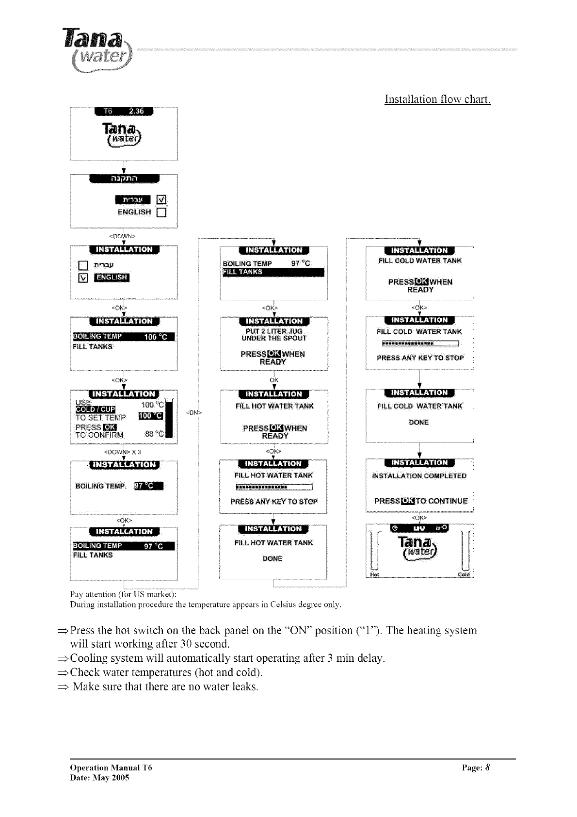
Installation flow chart.
[
<DOWN>
I
<OK>
T
_OK>
r
<DOWN> X 3
BOiL|NG TEMP
<OK>
I]IIII+[IP II_I+_4- +._- '-"_
F|LL TANNS
<OK>
FILL HOT WATER TANK
READY
<OK>
FILL HOT WATER TANK
[...................................................................
Pay attention (for US market):
During installation procedure the temperature appears in Celsius degree only.
_Press the hot switch on the back panel on the "ON" position ("l"). The heating system
will start working after 30 second.
Cooling system will automatically start operating after 3 min delay.
_Check water temperatures (hot and cold).
Make sure that there are no water leaks.
Operation Manual T6 Page: 8
Date: May 2005
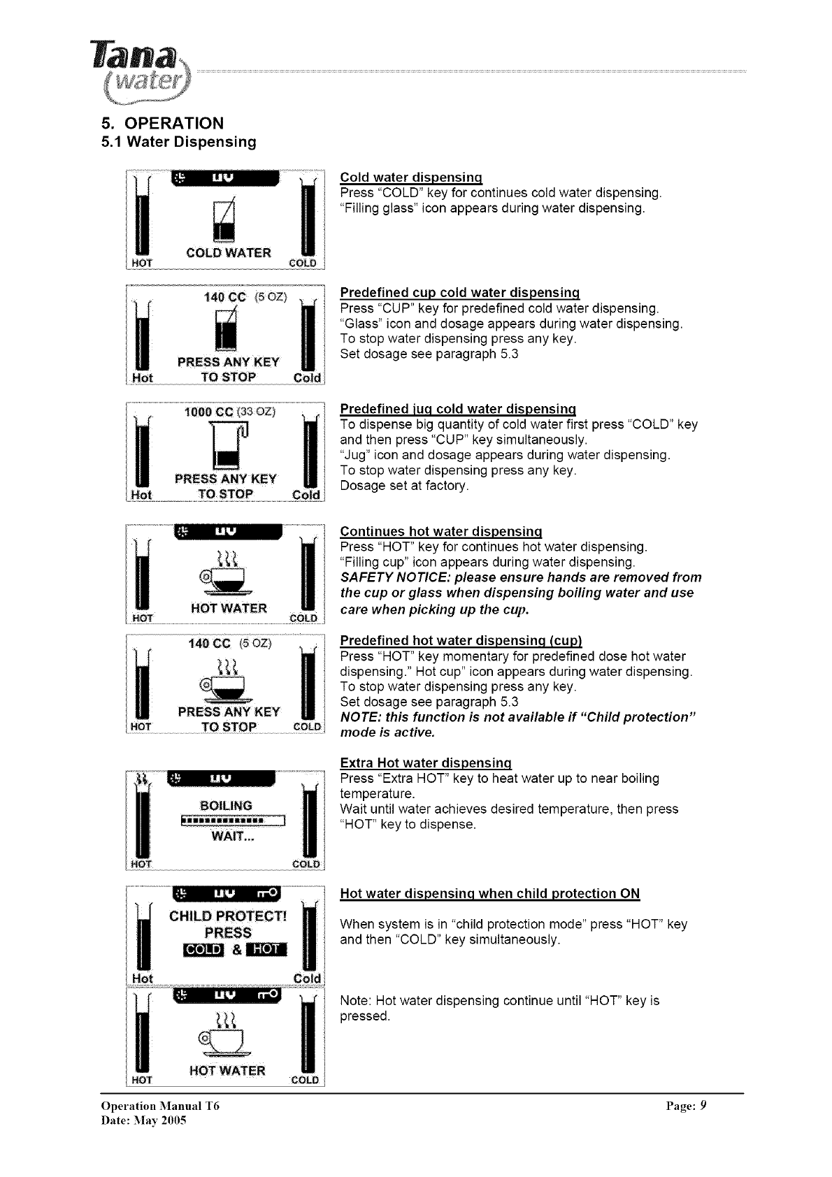
5. OPERATION
5.1 Water Dispensing
HOT COLD
140 CC (5OZ_
TO STOP
Cold water dispensinq
Press "COLD" key for continues cold water dispensing.
"Filling glass" icon appears during water dispensing.
Predefined cup cold water dispensinq
Press "CUP" key for predefined cold water dispensing.
"Glass" icon and dosage appears during water dispensing.
To stop water dispensing press any key.
Set dosage see paragraph 5.3
Predefined [uq cold water dispensinq
To dispense big quantity of cold water first press "COLD" key
and then press "CUP" key simultaneously.
"Jug" icon and dosage appears during water dispensing.
To stop water dispensing press any key.
Dosage set at factory.
Continues hot water dispensinq
Press "HOT" key for continues hot water dispensing.
"Filling cup" icon appears during water dispensing.
SAFETY NOTICE: please ensure hands are removed from
the cup or glass when dispensing boiling water and use
care when picking up the cup.
Predefined hot water dispensinq (cup)
Press "HOT" key momentary for predefined dose hot water
dispensing." Hot cup" icon appears during water dispensing.
To stop water dispensing press any key.
Set dosage see paragraph 5.3
NOTE: this function is not available if "Child protection"
mode is active.
BOILING
_i;iiliiiiWliii
WAIT.
Extra Hot water dispensinq
Press "Extra HOT" key to heat water up to near boiling
temperature.
Wait until water achieves desired temperature, then press
"HOT" key to dispense.
Hot water dispensinq when child protection ON
When system is in "child protection mode" press "HOT" key
and then "COLD" key simultaneously.
HOT HOT WATER
Note: Hot water dispensing continue until "HOT" key is
pressed.
Operation Manual T6 Page: 9
Date: :May 2005
140 CC (50Z)
HOT TO STOP cOLD
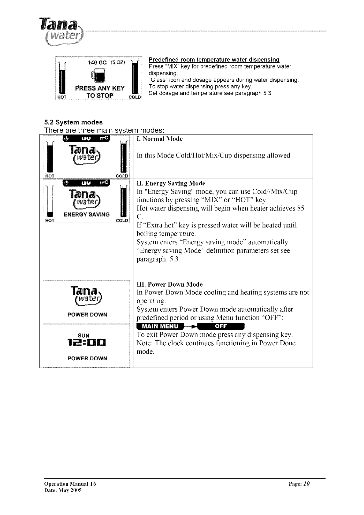
Predefined room temperature water dispensinq
Press "MIX" key for predefined room temperature water
dispensing.
"Glass" icon and dosage appears during water dispensing.
To stop water dispensing press any key.
Set dosage and temperature see paragraph 5.3
5.2 System modes
There are three main system modes:
I. Normal Mode
ENERGY SAVING
HOT COLD
POWER DOWN
SUN
POWER DOWN
In this Mode Cold/Hot/Mix/Cup dispensing allowed
II. Energy Saving Mode
In "Energy Saving" mode, you can use Cold//Mix/Cup
functions by pressing "MIX" or "HOT" key.
Hot water dispensing will begin when heater achieves 85
C.
If "Extra hot" key is pressed water will be heated until
boiling temperature.
System enters "Energy saving mode" automatically.
"Energy saving Mode" definition parameters set see
paragraph 5.3
III. Power Down Mode
In Power Down Mode cooling and heating systems are not
operating.
System enters Power Down mode automatically after
predefined period or using Menu function "OFF":
To exit Power Down mode press any dispensing key.
Note: The clock continues functioning in Power Done
mode.
Operation Manual T6 Page: 10
Date: May 2005
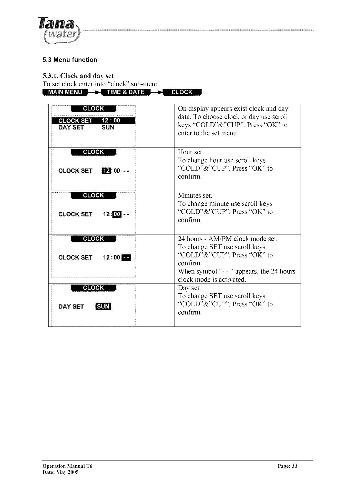
5.3 Menu function
5.3.1. Clock and day set
To set clock enter into "clock" sub-menu
==iSV:!l_l_M_[l == _I='_lhSIclr;!lI7'-_l|_ _--_lII@][
V+]I, [!I
DAYSET SUN
m;O0 -- I
[
[
[
[
li2_i--
t2: OOi
E
On display appears exist clock and day
data. To choose clock or day use scroll
keys "COLD"&"CUP". Press "OK" to
enter to the set menu.
Hour set.
To change hour use scroll keys
"COLD"&"CUP". Press "OK" to
confirm.
Minutes set.
To change minute use scroll keys
"COLD"&"CUP". Press "OK" to
confirm.
24 hours - AM/PM clock mode set.
To change SET use scroll keys
"COLD"&"CUP". Press "OK" to
confirm.
When symbol "- -" appears, the 24 hours
clock mode is activated.
Day set.
To change SET use scroll keys
"COLD"&"CUP". Press "OK" to
confirm.
g-klm
Operation Manual T6 Page: 11
Date: :May 2005
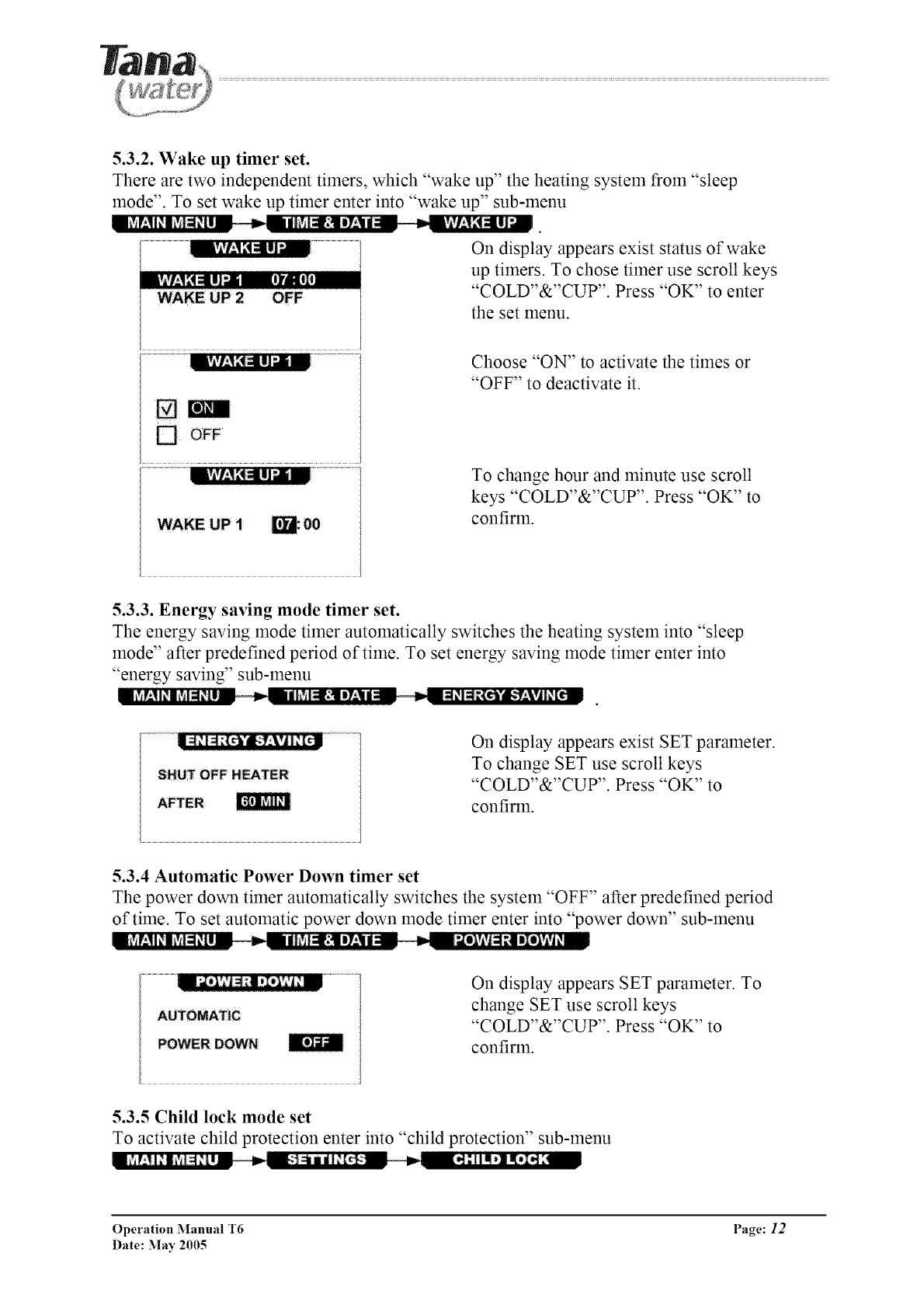
5.3.2. Wake up timer set.
There are two independent timers, which "wake up" the heating system from "sleep
mode". To set wake up timer enter into "wake up" sub-menu
On display appears exist status of wake
up timers. To chose timer use scroll keys
"COLD"&"CUP". Press "OK" to enter
the set menu.
[] OFF
Choose "ON" to activate the times or
"OFF" to deactivate it.
To change hour and minute use scroll
keys "COLD"&"CUP". Press "OK" to
confirm.
5.3.3. Energy saving mode timer set.
The energy saving mode timer automatically switches the heating system into "sleep
mode" after predefined period of time. To set energy saving mode timer enter into
"energy saving" sub-menu
l
AFTER
On display appears exist SET parameter.
To change SET use scroll keys
"COLD"&"CUP". Press "OK" to
confirm.
5.3.4 Automatic Power Down timer set
The power down timer automatically switches the system "OFF" after predefined period
of time. To set automatic power down mode timer enter into "power down" sub-menu
On display appears SET parameter. To
change SET use scroll keys
"COLD"&"CUP". Press "OK" to
confirm.
5.3.5 Child lock mode set
To activate child protection enter into "child protection" sub-menu
Operation Manual T6 Page: 12
Date: :May 2005
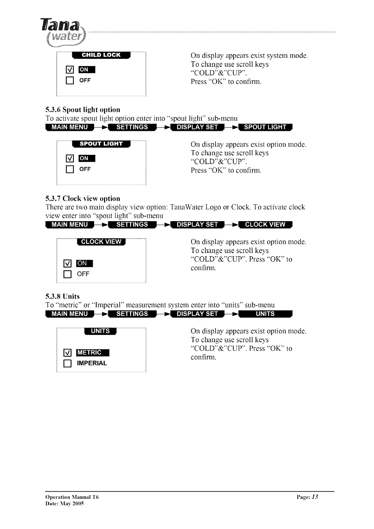
On display appears exist system mode.
To change use scroll keys
"COLD"&"CUP".
Press "OK" to confirm.
5.3.6 Spout light option
To activate spout light option enter into "spout light" sub-menu
On display appears exist option mode.
To change use scroll keys
"COLD"&"CUP".
Press "OK" to confirm.
5.3.7 Clock view option
There are two main display view option: TanaWater Logo or Clock. To activate clock
view enter into "spout light" sub-menu
On display appears exist option mode.
To change use scroll keys
"COLD"&"CUP". Press "OK" to
confirm.
5.3.8 Units
To "metric" or "Imperial" measurement system enter into "units" sub-menu
l_V_r;ll_l+Y++l_lZ__=_=_+']_llil_[t!_;_ _--=l]_.1;ll.'Vg-I=l-- = _= I1_11_
_; IMPERIAL
On display appears exist option mode.
To change use scroll keys
"COLD"&"CUP". Press "OK" to
confirm.
Operation Manual T6 Page: 13
Date: May 2005
5.3.9 Beep on key option
To activate spout beep-on-key option enter into "beep on key" sub-menu
n_+++T±ll+l?+l=l_tl-- _ ,,_+_:-+]_mil+[_++:_ ,,_ :]=_=I_,I[,1,+I[4_,
On display appears exist option state.
To change use scroll keys
[] om "COLD"&"CUP".
Press "OK" to confirm.
5.3.10 Language
To chose language enter into "language" sub-menu
On display appears exist language.
To change use scroll
"COLD"&"CUP".
Press "OK" to confirm.
keys
5.3.11 Restore factory settings
To restore factory settings enter into "restore settings" sub-menu
[]
On display appears exist system state.
To change use scroll keys
"COLD"&"CUP".
Press "OK" to confirm.
Default factory settings:
• child lock - activated
• automatic energy saving 60 min
• automatic power down OFF
• beep on key OFF
• spout light - ON
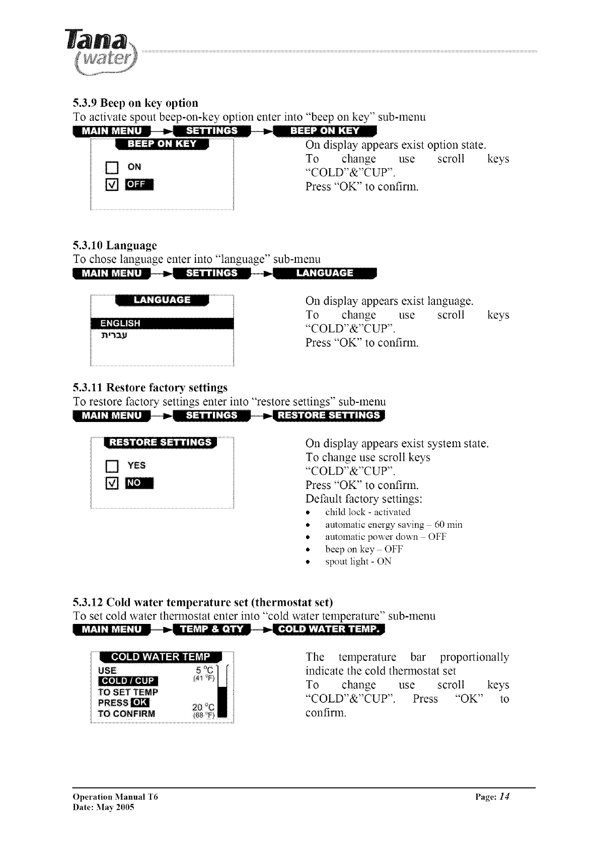
5.3.12 Cold water temperature set (thermostat set)
To set cold water thermostat enter into "cold water temperature" sub-menu
The temperature bar proportionally
indicate the cold thermostat set
To change use scroll keys
"COLD"&"CUP". Press "OK" to
confirm.
Operation Manual T6 Page: 14
Date: May 2005
5.3.13 Dosage cold water quantity set
To set cold water dispensing dose ("CUP" key) enter into "cold water quantity"
sub-menu
On the display appears current cold-water
dose set.
Setting range 60 - 300 cc (2-10 oz)
To change use scroll keys
"COLD"&"CUP".
Press "OK" to confirm.
5.3.14 MIX water temperature set
To set MIX (predefined temperature and quantity dispensing) water temperature enter
into "mix water temperature" sub-menu
The temperature bar proportionally
indicate the desired mix water
temperature set
To change use scroll keys
"COLD"&"CUP".
Press "OK" to confirm.
5.3.15 MIX water quantity set
To set MIX (predefined temperature and quantity dispensing) water dose quantity enter
into "mix water quantity" sub-menu
__- ,n __iM!:lT_,l:t/l_lDi/,.__
USE
TO SET TEMP [_
[R_rI_L1N
140 ¢C
TO CONFIRM
On the display appears current mix-water
dose set.
Setting range 60 - 300 cc (2-10 oz)
To change use scroll keys
"COLD"&"CUP".
Press "OK" to confirm.
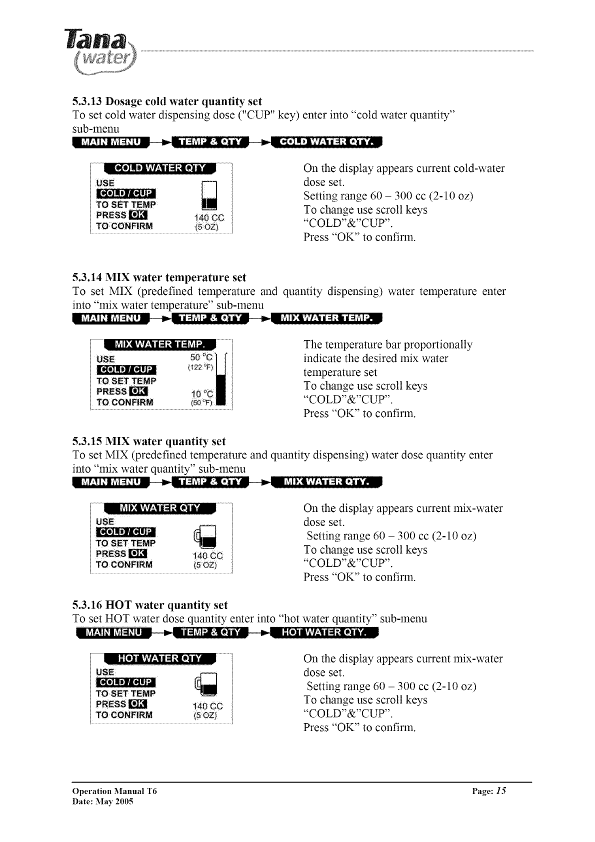
5.3.16 HOT water quantity set
To set HOT water dose quantity enter into "hot water quantity" sub-menu
il [el Ivlvf:|d i ;ilI i TM On the display appears current mix-water
dose set.
Setting range 60 - 300 cc (2-10 oz)
To change use scroll keys
"COLD"&"CUP".
Press "OK" to confirm.
[_g_]mli]l[itl_
Operation Manual T6 Page: 15
Date: :May 2005
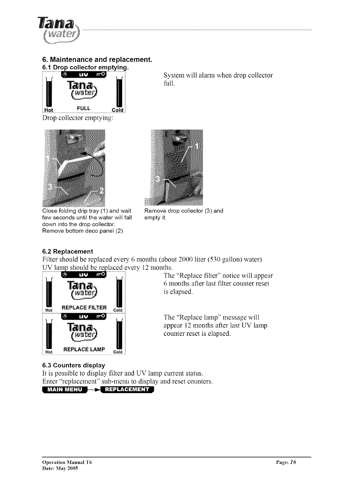
6. Maintenance and replacement.
6.1 Drop collector emptying.
System will alarm when drop collector
full.
Drop collector emptying:
Close folding drip tray (1) and wait
few seconds until the water will fall
down into the drop collector.
Remove bottom deco panel (2)
Remove drop collector (3) and
empty it.
6.2 Replacement
Filter should be replaced every 6 months (about 2000 liter (530 gallon) water)
UV should be alaced every 12 months.
The "Replace filter" notice will appear
6 months after last filter counter reset
is elapsed.
The "Replace lamp" message will
appear 12 months after last UV lamp
counter reset is elapsed.
6.3 Counters display
It is possible to display filter and UV lamp current status.
Enter "replacement" sub-menu to display and reset counters.
Operation Manual T6 Page: 16
Date: May 2005
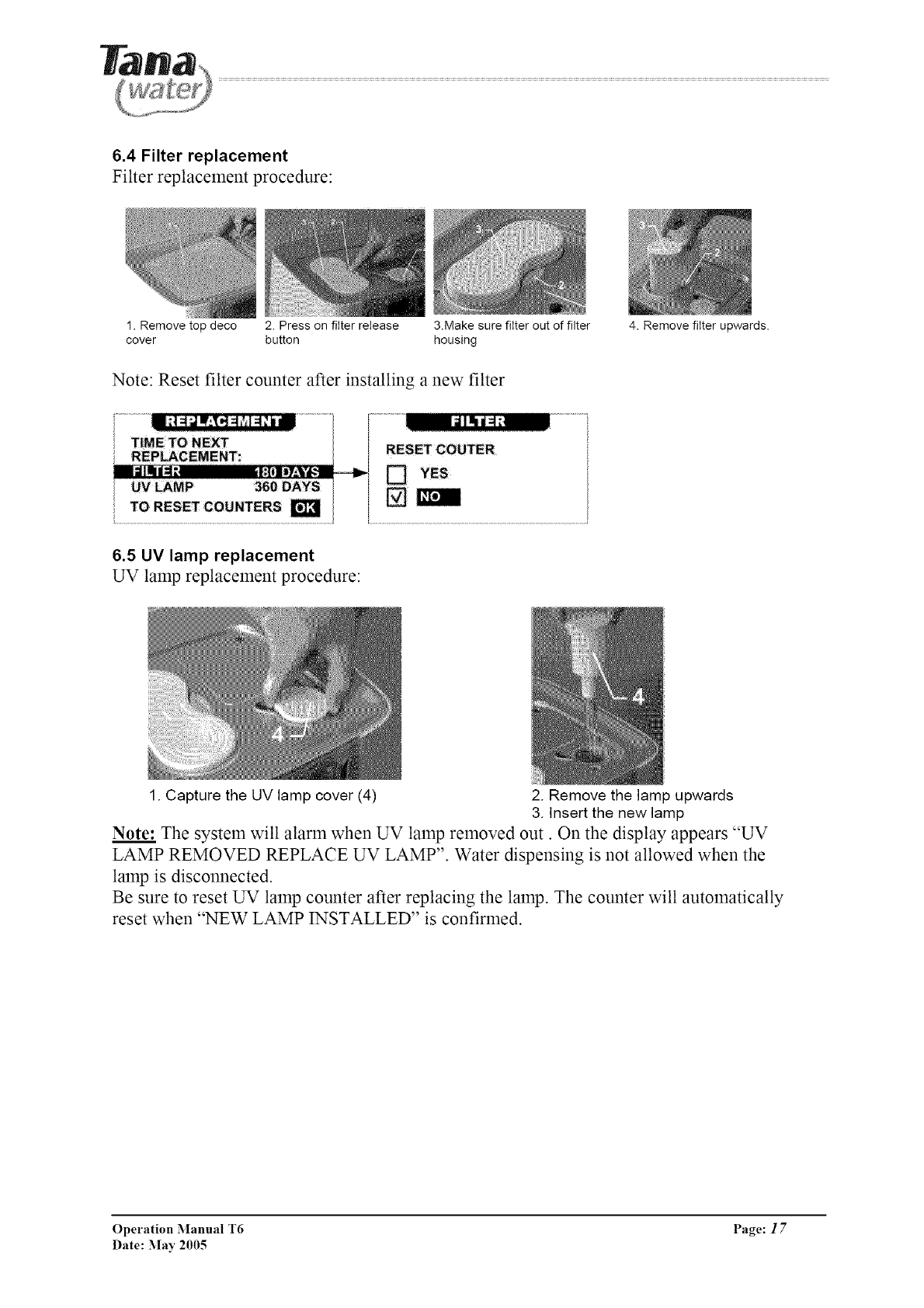
6.4 Filter replacement
Filter replacement procedure:
1. Remove top deco 2. Press on filter release 3.Make sure filter out of filter
cover button housing
Note: Reset filter counter after installing a new filter
4. Remove filter upwards.
6.5 UV lamp replacement
UV lamp replacement procedure:
1. Capture the UV lamp cover (4) 2. Remove the lamp upwards
3. Insert the new lamp
Note: The system will alarm when UV lamp removed out. On the display appears "UV
LAMP REMOVED REPLACE UV LAMP". Water dispensing is not allowed when the
lamp is disconnected.
Be sure to reset UV lamp counter after replacing the lamp. The counter will automatically
reset when "NEW LAMP INSTALLED" is confirmed.
Operation Manual T6 Page: 17
Date: May 2005
7. Cleaning the appliance
Use only a soft cloth and warm, soapy water when cleaning the appliance, and a dry cloth only
when cleaning the operating panel.
The top and bottom trays are suitable for dishwasher cleaning. Please do not use harsh detergents,
concentrated liquid cleaners, solvents or any material likely to scratch the appliance's casing (i.e.
Scotch-Brite, steel wool, etc.).
Please note: The appliance is connected to an electrical source. Do not wet the back of the
machine.
8. Weekends /Holidays /Vacations
For safety reasons, if you plan not to use the machine for a day or more, please disconnect the
appliance from its electrical source and close the water inlet port. After reconnecting, allow water
to flow through the appliance for 5-10 minutes.
9. Warning * Safety * Service
Warning: Moving the appliance may cause flooding.
The T-6 model operates using a 230/115V Volt electrical current, and must be connected to a
socket with a 10 Ampere fuse. During operation and maintenance, please take all safety measures
required for operation of an electrical appliance.
This appliance dispenses water at a very high temperature - do not let children use it without
adult supervision. The activation of a "Child Safety" mode is possible - please see the explanation
on page 9, part 3.
Warning: Warm water is dispensed through two different spouts. To pour warm water into a
bottle with a narrow spout, please use a tunnel, or first dispense the water into a container with a
wide spout.
Operation Manual T6 Page: 18
Date: May 2005
In the case of any announcements from the Ministry of Health regarding water sanitary failure or
fault, drinking water must be boiled and Ministry of Health instructions followed.
After any such sanitary fault or t:ailure is declared resolved, we recommend that the filter be
replaced.
The water system is secure as the tanks are not pressurized and open as there are no valves
between the hot or cold water tanks and the spout. Therefore, light dripping as a result of water
flow is standard and to be expected.
During the filtration process, phosphorus ions are emitted into the water in volume lower than the
maximal amount permitted by drinking water standards. We recommend that people with health
issues consult a physician before using the system.
Maintenance and service of the dispenser must be performed by certified company service
personnel. The manut:acturer, Tana Water, relinquishes any responsibility for injury or damage to
property as a result of improper use or maintenance of this appliance.
For further information, explanations regarding operation and care, contact your local
distributor.
Operation Manual T6 Page: 19
Date: May 2005
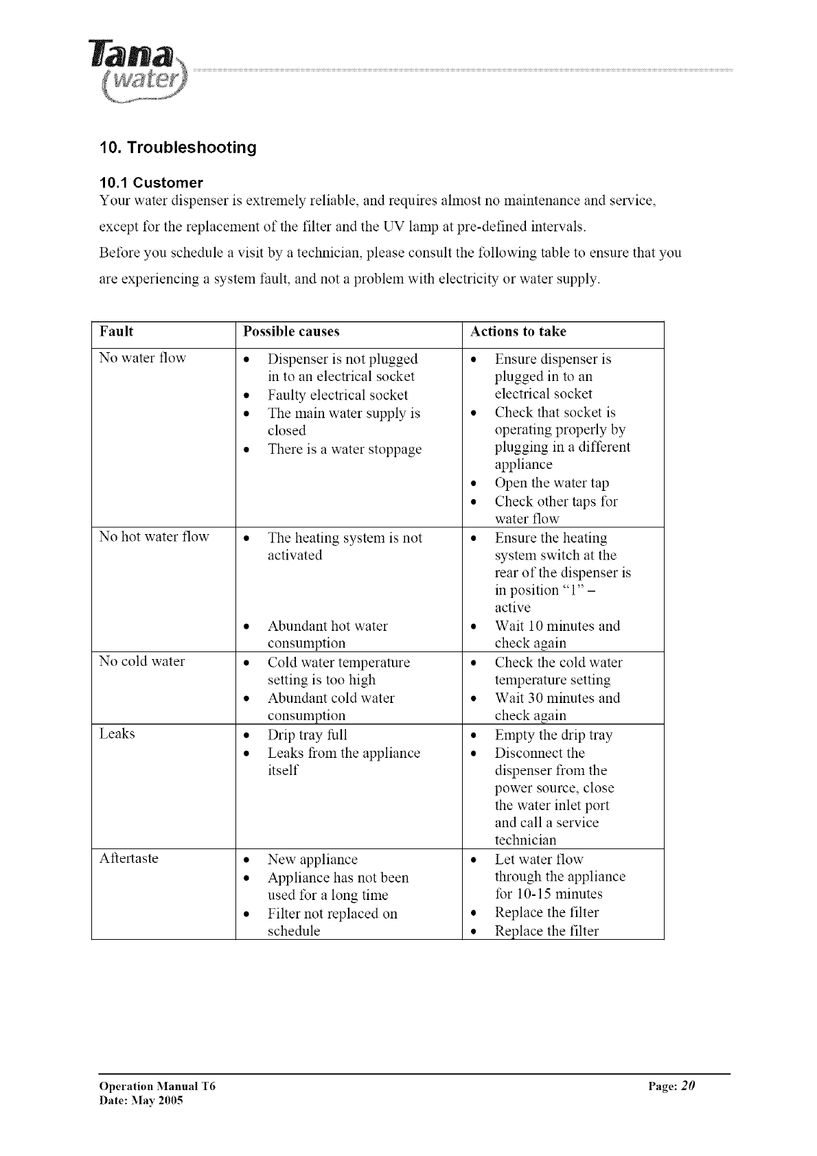
10. Troubleshooting
10.1 Customer
Your water dispenser is extremely reliable, and requires ahnost no maintenance and service,
except for the replacement of the filter and the UV lamp at pre-defined intervals.
Before you schedule a visit by a technician, please consult the following table to ensure that you
are experiencing a system t:ault, and not a problem with electricity or water supply.
Fault Possible causes Actions to take
No water flow ,
No hot water flow
• Dispenser is not plugged
in to an electrical socket
• Faulty electrical socket
• The main water supply is
closed
• There is a water stoppage
No cold water
Leaks
Aftertaste
• The heating system is not
activated
• Abundant hot water
consumption
• Cold water temperature
setting is too high
• Abundant cold water
consumption
• Drip tray full
• Leaks from the appliance
itself
• New appliance
• Appliance has not been
used for a long time
• Filter not replaced on
schedule
Ensure dispenser is
plugged in to an
electrical socket
• Check that socket is
operating properly by
plugging in a different
appliance
• Open the water tap
• Check other taps for
water flow
• Ensure the heating
system switch at the
rear of the dispenser is
in position "1" -
active
• Wait 10 minutes and
check again
• Check the cold water
temperature setting
• Wait 30minutes and
check again
• Empty the drip tray
• Disconnect the
dispenser from the
power source, close
the water inlet port
and call a service
technician
• Let water flow
through the appliance
for 10-15 minutes
• Replace the filter
• Replace the filter
Operation Manual T6 Page: 20
Date: May 2005
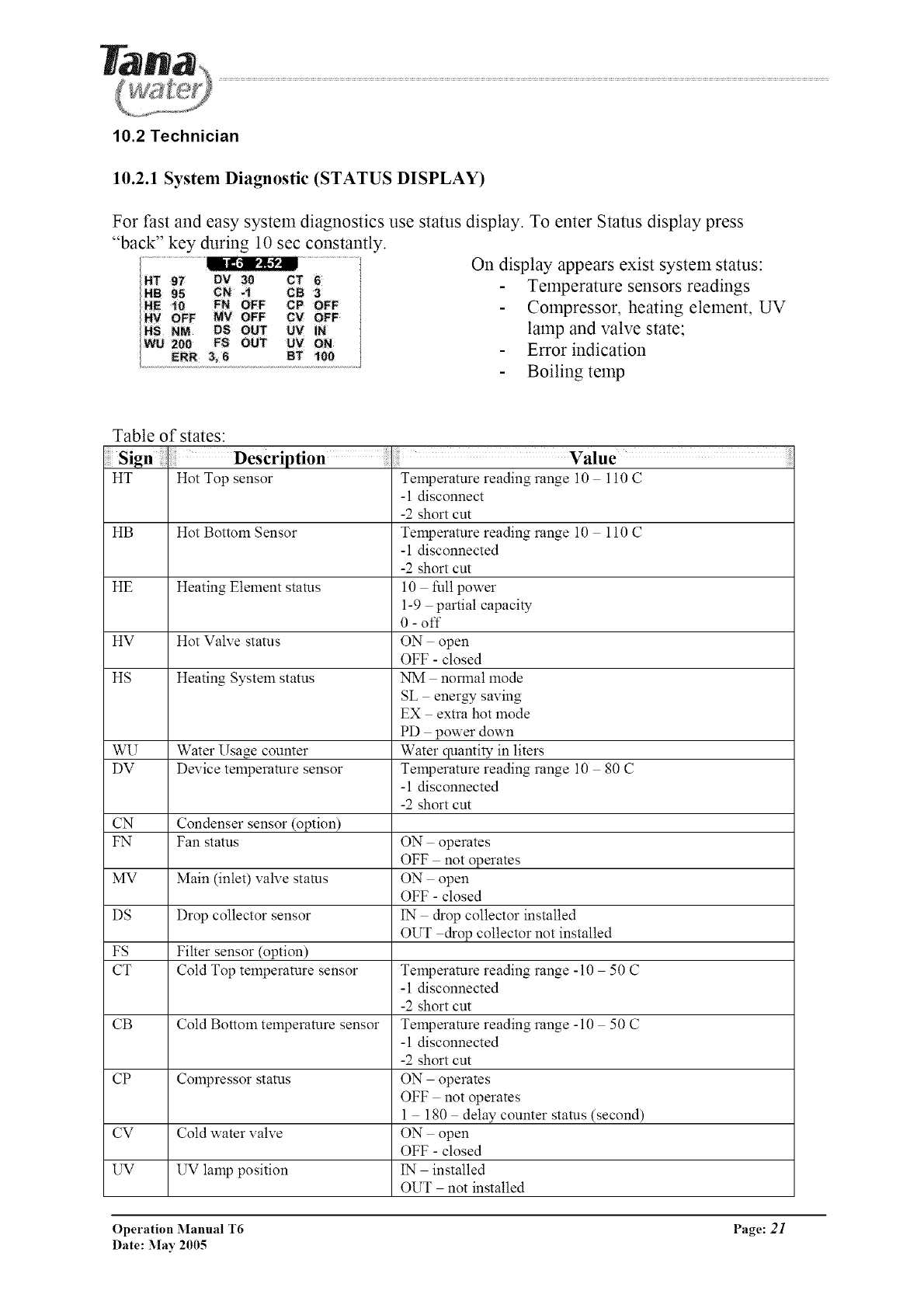
10.2 Technician
10.2.1 System Diagnostic (STATUS DISPLAY)
For fast and easy system diagnostics use status display. To enter Status display press
"back" key during 10 sec constantly.
On display appears exist system status:
Temperature sensors readings
Compressor, heating element, UV
lamp and valve state;
Error indication
Boiling temp
Table of states:
HT Hot Top sensor
HB Hot Bottom Sensor
HE Heating Element stares
HV Hot Valve status
HS Heating System status
WU Water Usage counter
DV Device temperature sensor
CN Condenser sensor (option)
Temperature reading range 10 110 C
-1 disconnect
-2 short cut
Temperature reading range 10 110 C
-1 disconnected
-2 short cut
10 thll power
1-9 partial capacity
0 - off
ON open
OFF - closed
NM normal mode
SL energy saving
EX extra hot mode
PD power down
Water quantity in liters
Temperature reading range 10 80 C
-1 disconnected
-2 short cut
FN Fan status ON operates
OFF not operates
MV Main (inlet) valve stares ON open
OFF - closed
DS Drop collector sensor 1N drop collector installed
OUT drop collector not installed
FS Filter sensor (option)
CT Cold Top telnperature sensor Temperature reading range -10 50 C
-1 disconnected
-2 short cut
CB Cold Bottom temperature sensor Temperature reading range - 10 50 C
-1 disconnected
-2 short cut
CP Colnpressor status ON operates
OFF not operates
1 180 delay counter stares (second)
CV Cold water valve ON open
OFF - closed
UV UV lamp position 1N installed
OUT not installed
Operation Manual T6 Page: 21
Date: May 2005
UV
BT
ERR
UV lamp stares
Boiling temperature set
Error status
ON operates
OFF not operates
Current Boiling Temperature set, °C/_'F
Error see table par. 10.2.1
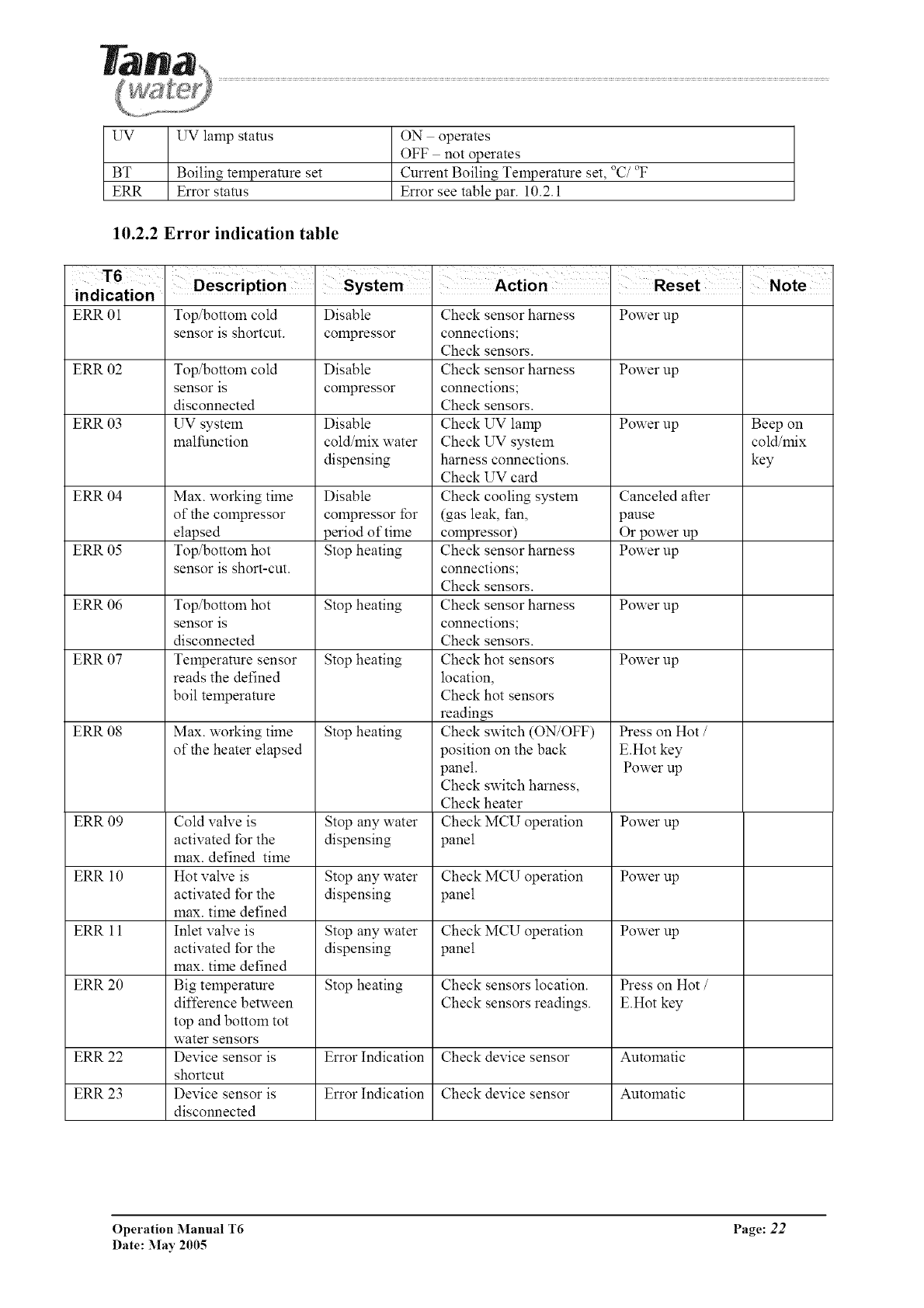
10.2.2 Error indication table
T6
indication
ERR 01 Top/bottom cold Disable Check sensor harness Power up
sensor is shortcut, compressor connections;
Check sensors.
ERR 02 Top/bottom cold Disable Check sensor harness Power up
sensor is compressor connections;
disconnected Check sensors.
ERR 03 UV system Disable Check UV lamp Power up Beep on
malfunction cold/mix water Check UV system cold/mix
dispensing harness connections, key
Check UV card
ERR 04 Max. working time Disable Check cooling system Canceled after
of the compressor colnpressor for (gas leak, fan, pause
elapsed period of time colnpressor) Or power up
ERR 05 Top/bottom hot Stop heating Check sensor harness Power up
sensor is short-cut, connections;
Check sensors.
ERR 06 Top/bottom hot Stop heating Check sensor harness Power up
sensor is connections;
disconnected Check sensors.
ERR 07 Temperature sensor Stop heating Check hot sensors Power up
reads the defined location,
boil temperature Check hot sensors
readings
ERR 08 Max. working time Stop heating Check switch (ON/OFF) Press on Hot /
of the heater elapsed position on the back E.Hot key
panel. Power up
Check switch harness,
Check heater
ERR 09 Cold valve is Stop any water Check MCU operation Power up
activated for the dispensing panel
max. defined time
ERR 10 Hot valve is Stop any water Check MCU operation Power up
activated for the dispensing panel
max. time defined
ERR 11 Inlet valve is Stop any water Check MCU operation Power up
activated for the dispensing panel
max. time defined
ERR 20 Big temperature Stop heating Check sensors location. Press on Hot /
difference between Check sensors readings. E.Hot key
top and bottom tot
water sensors
ERR 22 Device sensor is Error Indication Check device sensor Automatic
shortcut
ERR 23 Device sensor is Error Indication Check device sensor Automatic
disconnected
Operation Manual T6 Page: 22
Date: May 2005
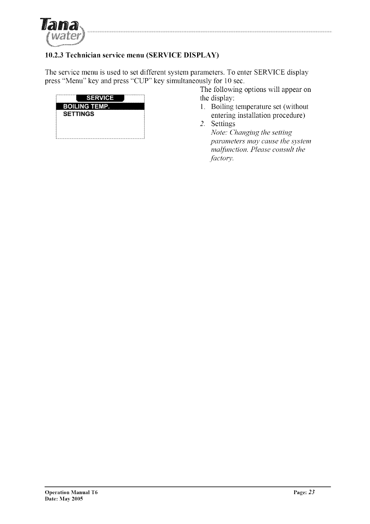
10.2.3 Technician service menu (SERVICE DISPLAY)
The service menu is used to set different system parameters. To enter SERVICE display
press "Menu" key and press "CUP" key simultaneously for 10 sec.
The following options will appear on
the display:
1. Boiling temperature set (without
SETTINGS entering installation procedure)
2. Settings
Note." Changing the setting
parameters may cause the system
malfimction. Please consult the
factoly.
Operation Manual T6 Page: 23
Date: May 2005
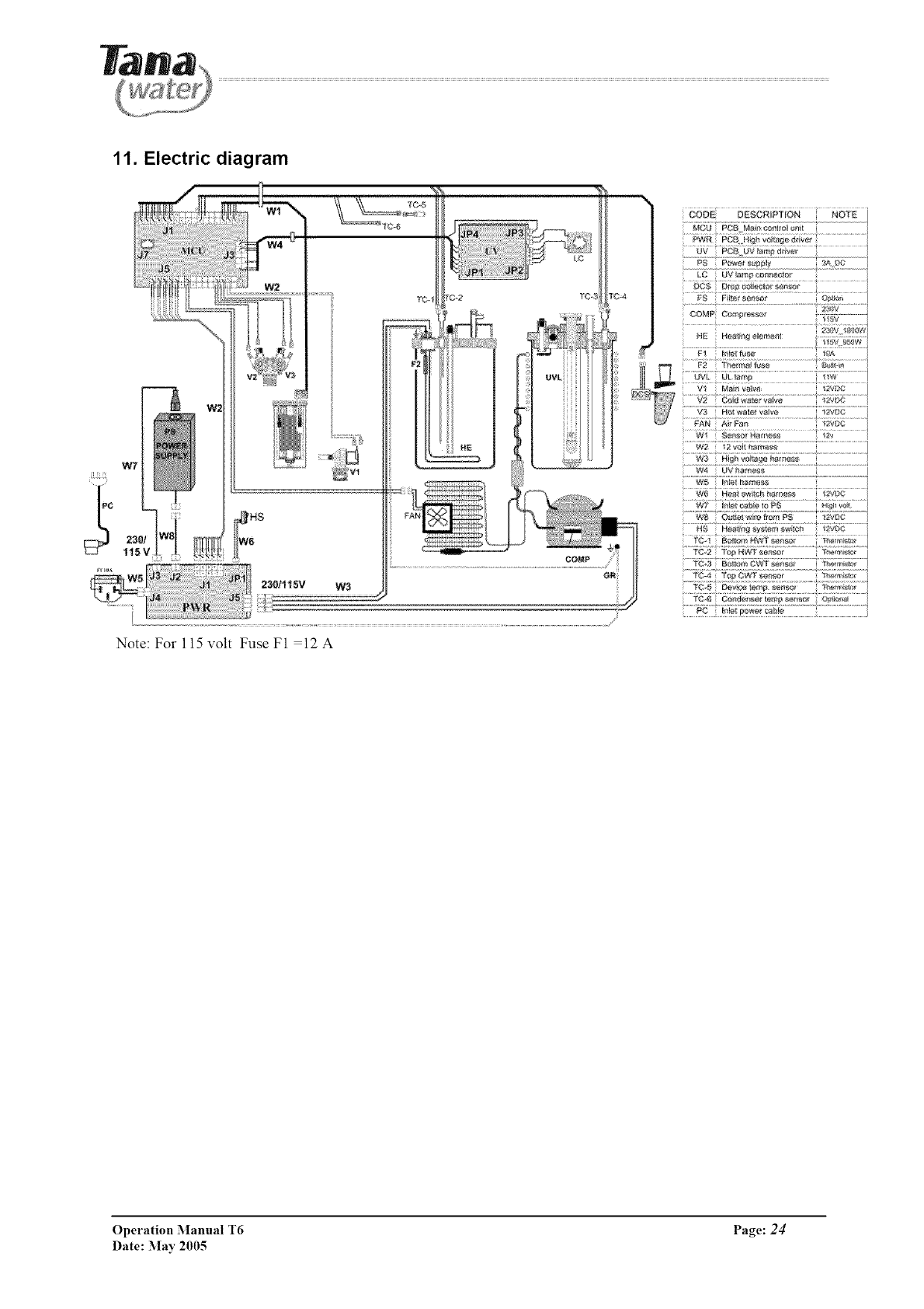
11. Electric diagram
Note: For 115 volt Fuse F1 =12 A
_V P¢_ UV _m) @iv÷
_C5 D_r_c@ierlorser_sr
.................................................................................>z2.LW.....................
......w2 2voi _tam_ss...............................................
....w:_ UV_"_s_.....................................................
........]{_:!, _[W_!R cf?s....................._' _'_!!
....X9:! ......
...... .......................' _t"F'.......
Operation Manual T6 Page: 24
Date: May 2005
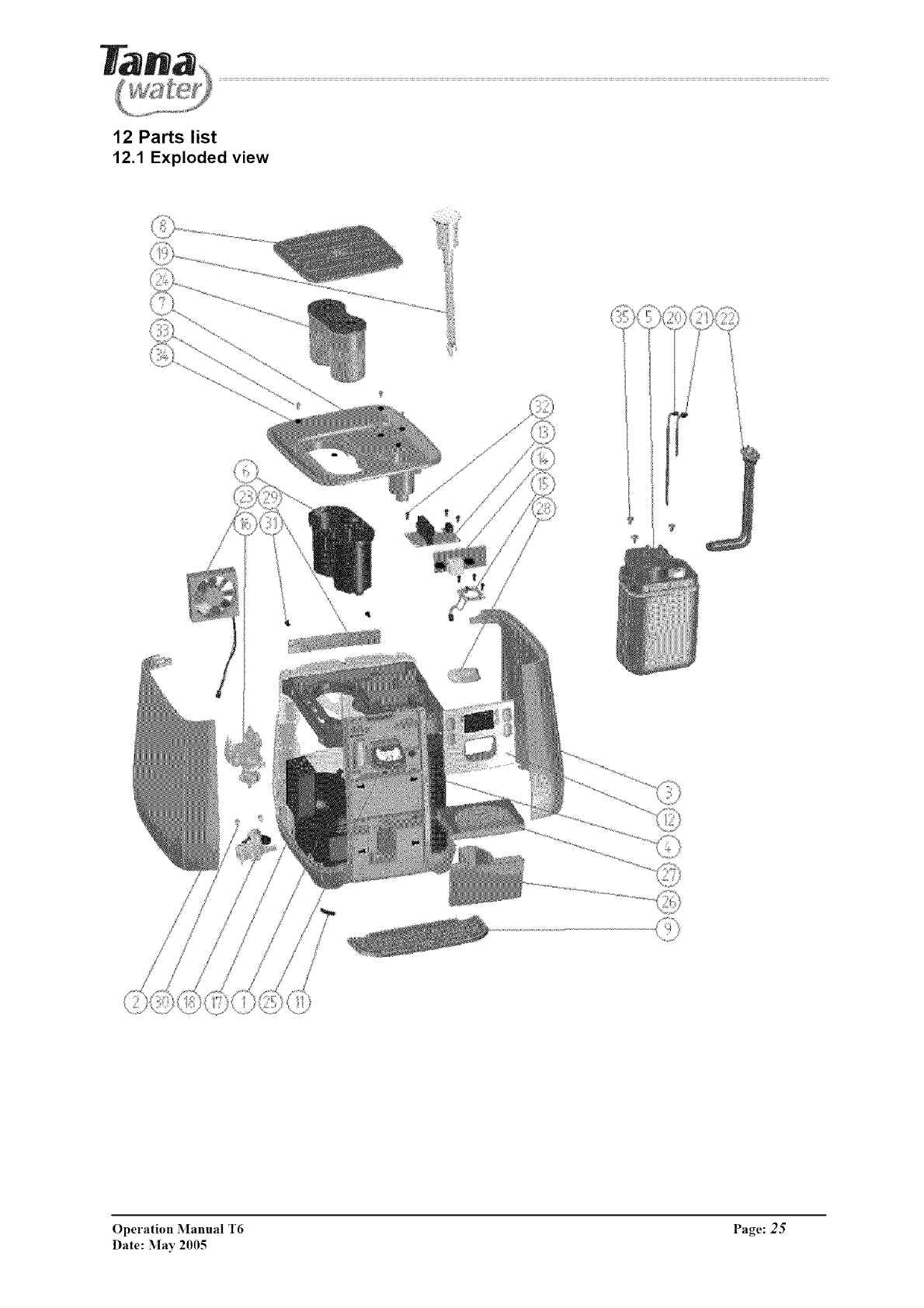
12 Parts list
12.1 Exploded view
Operation Manual T6 Page: 25
Date: :May 2005
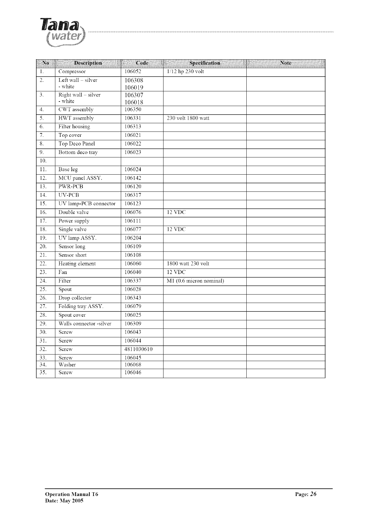
i. Compressor 106052 1/12 hp 230 volt
2. Left wall silver 106308
- white 106019
3. Right wall silver 106307
- white 106018
4. CWT assembly 106350
5. HWT assembly 106331 230 volt 1800 watt
6. Filter housing 106313
7. Top cover 106021
8. Top Deco Panel 106022
9. Bottom deco tray 106023
i0.
11. Base leg 106024
12. MCU panel ASSY. 106142
13. PWR-PCB 106120
14. UV-PCB 106317
15. UV lamp-PCB connector 106123
16. Double valve 106076 12 VDC
17. Power supply 106111
18. Single valve 106077 12 VDC
19. UV lamp ASSY. 106204
20. Sensor long 106109
21. Sensor short 106108
22. Heating element 106060 1800 watt 230 volt
23. Fan 106040 12 VDC
24. Filter 106337 M1 (0.6 micron nominal)
25. Spout 106028
26. Drop collector 106343
27. Folding tray ASSY. 106079
28. Spout cover 106025
29. Walls connector -silver 106309
30. Screw 106043
31. Screw 106044
32. Screw 4811030610
33. Screw 106045
34. Washer 106068
35. Screw 106046
Operation Manual T6 Page: 26
Date: May 2005
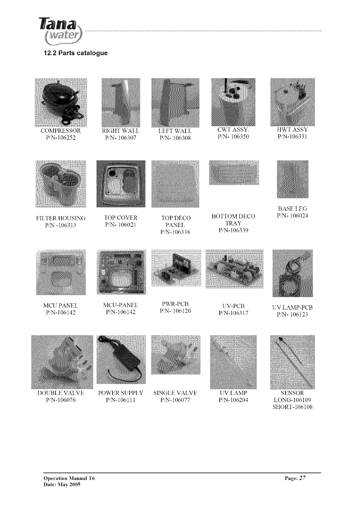
12.2 Parts catalogue
COMPRESSOR RIGHT WALL LEFT WALL CWT ASSY. HWT ASSY
P/N-106252 P/N- 106307 P/N- 106308 P/N- 106350 P/N-106331
FILTER HOUSING
P/N -106313
TOP COVER TOP DECO BOTTOM DECO
P/N- 106021 PANEL TRAY
P/N-106338 P/N-106339
BASE LEG
P/N- 106024
MCU PANEL MCU-PANEL PWR-PCB UV-PCB UV LAMP-PCB
P/N-106142 P/N-106142 P/N- 106120 P/N-106317 P/N- 106123
DOUBLE VALVE
P/N- 106076
POWER SUPPLY SINGLE VALVE
P/N- 106111 P/N- 106077
UV LAMP
P/N- 106204
SENSOR
LONG- 106109
SHORT- 106108
Operation Manual T6 Page: 2 7
Date: May 2005
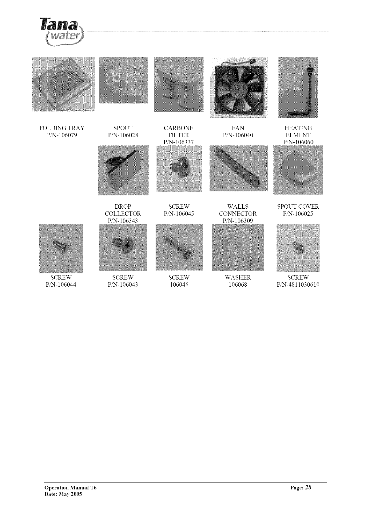
FOLDING TRAY
P/N- 106079
SCREW
P/N-106044
SPOUT CARBONE FAN HEATING
P/N- 106028 FILTER P/N- 106040 ELMENT
P/N- 106337 P/N- 106060
DROP SCREW WALLS SPOUT COVER
COLLECTOR P/N- 106045 CONNECTOR P/N- 106025
P/N- 106343 P/N- 106309
SCREW SCREW WASHER SCREW
P/N- 106043 106046 106068 P/N-4811030610
Operation Manual T6 Page: 28
Date: May 2005
