Users Manual
330
A-MIS 330 Installation and user guide
www.hd1py.com
®
1 2
3 4
5 6
7 8
9 0
C
2
Environmental information
• When returning the AIVIA, you should only use the origi-
nal packaging.
• Dispose of the AIVIA properly in accordance with all
state, province and country regulations.
• Recycle or dispose of the batteries and lithium batteries
in accordance with all federal, state and local laws. To
avoid fire and explosion hazard, do not burn or incinerate
the batteries. The proper disposal of used batteries pre-
serves the environment and your health.
Warranty
• Limited Warranty, warranty is void:
- For defects that are the result of materials and products
supplied by Reseller or end user;
- For defects that are the result of assembly or installation
made by Reseller or end user ; Do not insert any objects
into any openings; Do not disassemble the various
elements that make up the AIVIA; Only qualified
personnel may carry out repairs on the AIVIA;
- For defects resulting wholly or partially from normal
wear and tear of consumables (accumulator, batteries, et
cetera), from damages or accidents attributable to
Reseller or end user;
- In case of any modifications or abnormal uses that do
not conform with the product's purpose or usual functions;
and if the product is used in such a way that goes against
the advice or recommendations provided by Supplier;
Any operation or assembly procedures expressly
prohibited or not recommended by this manual are
forbidden;
- In case of negligence, insufficient supervision or
maintenance on the part of the Reseller or end user;
- In case of force majeure.
Maintenance
CAUTION
THE AIVIA CONTAINS BATTERIES.
THERE IS A RISK OF EXPLOSION IF THE BATTERIES
SUPPLIED FOR USE WITH THE AIVIA ARE
REPLACED BY INCORRECT BATTERIES.
ONLY AN AUTHORIZED OPERATOR CAN CARRY
OUT MAINTENANCE OPERATIONS, INCLUDING
REPLACING THE BATTERIES.
Safety
• To avoid risk of fire or electric shock, the AIVIA should
not be exposed to any naked flame.
• Leave a space of at least 5 inches around the AIVIA to
assure proper ventilation.
• Keep the AIVIA away from radiators or any other heat
sources.
• Do not place the AIVIA near any devices that generate
heat. Do not place anything under the AIVIA.
• To avoid damage, do not insert objects into any of the
openings in the AIVIA.
• Never install the AIVIA in direct exposure to sunlight.
• Do not expose the AIVIA to any moisture when the door
is open.
• The mounting screws must be adapted to the type of
surface which the AIVIA is attached to.
• The manufacturer cannot be held liable for improper
installation or in the case of an accident or injury during its
installation.
Important
Read this manual before installation and use of the AIVIA.
Read this section carefully and follow the instructions.
The warranty does not cover damage caused by failure to
follow these instructions.
Installation must be carried out by a qualified operator or
authorized by the AIVIA’s manufacturer.
Never install an AIVIA in direct exposure to sunlight.
The unheated AIVIA must be installed in a temperate
environment, in accordance with the manufacturer’s
s p e c i f i c a t i o n s f o r t h e d e f i b r i l l a t o r .
The heated AIVIA must be installed in an environment
that respects the operating temperatures of the AIVIA.
You must monitor and follow up alerts related to
temperature.
The characteristics of the AIVIA are subject to changes
without notice.
The manufacturer of the AIVIA reserves the right to
change products at any time, including unlimited
modifications to previously delivered products.
AIVIA® is a registered trade-mark of PYRESCOM, used
under license.
Patent Pending.
3
Installation 4
Important 5
Aivia components 5
Identification label 5
Initial opening
5
Aivia installation 6
Installing the SIM card 7
Ethernet LAN network connections 8
Connecting the power supply 8
Setting up the defibrillator 9
AED Status sensor installation 9
AED Status sensor calibration 9
Closing the Aivia door 9
Summary
Operation 19
Low light mode operation 20
Heating option operation 20
AED removal Alert 20
Temperature Alerts 20
Pictograms 20
Using the Aivia 20
Diagnosis / Troubleshooting 25
LCD Display status 26
Diagnosis / Troubleshooting 27
Electrical installation / Specifications 28
Power Supply 29
Mechanical properties 30
Technical properties 30
Compliance 30
Configuration 10
Setting up the Aivia 11
Maintenance 21
Opening the Aivia in maintenance mode 22
Hatch opening and closing 22
AED Status sensor calibration in Maintenance mode 23
AED Status sensor LED indicator 23
Shutting down the Aivia 23
Aivia maintenance 23

4
Contents
This section will allow you to carry out the physical
installation of your Aivia, and to connect the different
cables needed in order to make it work. SIM card
installation in case of the optional GSM-3G Aivia is also
described.
330
Installation
GSM Option
If you have the GSM option (written on your Aivia
identification label), you will not have to connect the
phone cable, but you will have to insert the SIM card into
the Aivia.
3G Option
If you have the 3G option (written on your Aivia
identification plate), you will not have to connect the
Ethernet cable, but you will have to insert the SIM card
into the Aivia.
5
Installation
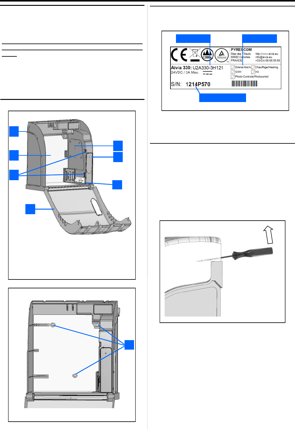
Identification label
• The identification label is situated inside the Aivia
• In the event you need to contact customer services or
your distributor, please make sure you have your Aivia
reference and serial number available.
Initial opening
• To open the Aivia door before it is installed on the wall,
use a small screwdriver.
• Slide the screwdriver between the door and the chassis
of the Aivia.
• Pull the screwdriver upward, being careful not to make
any marks on the Aivia.
• Repeat the above steps on the other side of the Aivia.
Serial number
Reference Options
Important
Read this manual with caution before setting up and us-
ing the Aivia.
Never install Aivia in direct exposure to sunlight. You
risk exposing the defibrillator to excessive tempera-
tures.
Aivia contains batteries.
There is a risk of explosion if the batteries in the
Aivia are replaced by incorrect type batteries. Only
an authorized technician may replace the batteries.
1. Electronic compartment
2. Light sensor
3. Seal support
4. Heating film
5. low light and alert indicators
6. Door
7. Identification label
1
2
4
3
6
5
7
8
8. Mounting holes
AIVIA components
6
Installation
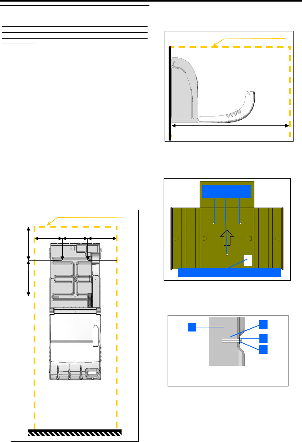
• Leave an clear space of 55 1/8" (140 cm) in front of the
wall where the AIVIA is installed to allow its door to open
easily.
• To mark the fixations and cable route, use the drilling
template provided with the packing.
• Put the template against the wall, with the arrow facing
upwards and towards you.
• Use a suitable mounting method for the type of surface
on which the AIVIA is to be mounted.
• The mounting system must be able to support a
minimum load of 44 lb (20 kg).
• The screw head and washer together must not exceed
5/16" (8 mm) thickness.
• Run all the necessary cables through the hole before
mounting the AIVIA to the wall.
Affix the AIVIA using the 3 mounting holes
Fixation holes
24 VDC and Ethernet Cables passage
55 1/8" (1400 mm)
Useful area for AIVIA working space
1 2
3
4
1. Wall surface
2. Screw plug
3. Mounting screw, M6 minimum, M8 maximum
4. Flat washer 9/16" (14 mm) maximum
AIVIA Installation
Never install the AIVIA in direct exposure to sunlight. The
AIVIA must be installed in a protected environment,
conforming with the instructions of the defibrillator
manufacturer.
• Installation must be carried out by a qualified operator
who adheres to the Bornavie charter or authorized by the
AIVIA manufacturer.
• If the AIVIA is installed in a public street or place with
public access, install a ground support structure
(abutment) or column. Please remember that it must
comply with the regulation in force regarding accessibility
standards in each country, state and / or area.
• The ADA (Americans with Disabilities Act) guidelines
specify that in an un-obstructed approach, the reach to
the door handle shall not exceed 48" (122 cm) from the
floor. The maximum side reach is to be less than 54" (137
cm).
• The mounting screws must be suitable for the type of
surface on which the AIVIA is mounted.
• Allow for a free working area when installing the AIVIA
as specified in the diagrams below.
• The exact dimensions of the AIVIA are provided at the
end of this document in the section "Specifications."
Useful area for AIVIA working space
8 7/16"
(215 mm)
7 1/2"
(190 mm)
8 11/16"
(220 mm)
5 15/16"
(150 mm)
8 11/16"
(220 mm)
5/16"
(8.5 mm)
7
Installation
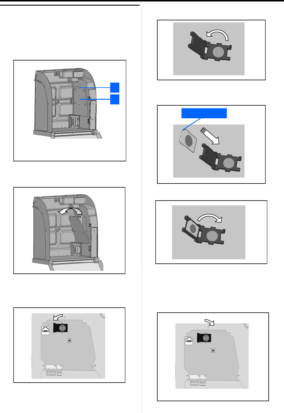
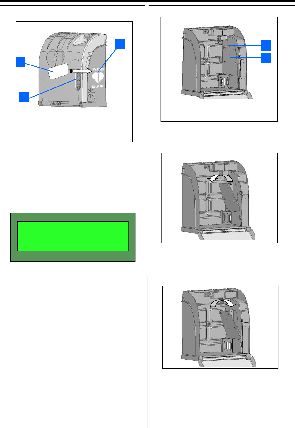
Installing the SIM card
SIM card installation must be done when the Aivia is
switched off. PIN Code must be set up in the Aivia,
refer to the "Setting up the Aivia" section.
• If your Aivia is equipped with the GSM option, you must
insert the SIM card into its socket.
• Remove the access door screw with a Philips
screwdriver and pull door away from the top.
• Unlock the base of the SIM card by rotating the metal
plate 45º counter clockwise.
• Pull up the cover to insert the SIM card.
• Insert the SIM card, ensuring it is inserted in the proper
direction with reference to the notched edge.
• Gently close the SIM card cover.
• If the cover does not close correctly, check the
orientation of the SIM card.
• Lock the base of the SIM card by rotating the metal plate
45º clockwise.
Notch
1
2
1. Access door screws.
2. Battery access door.
8
Installation
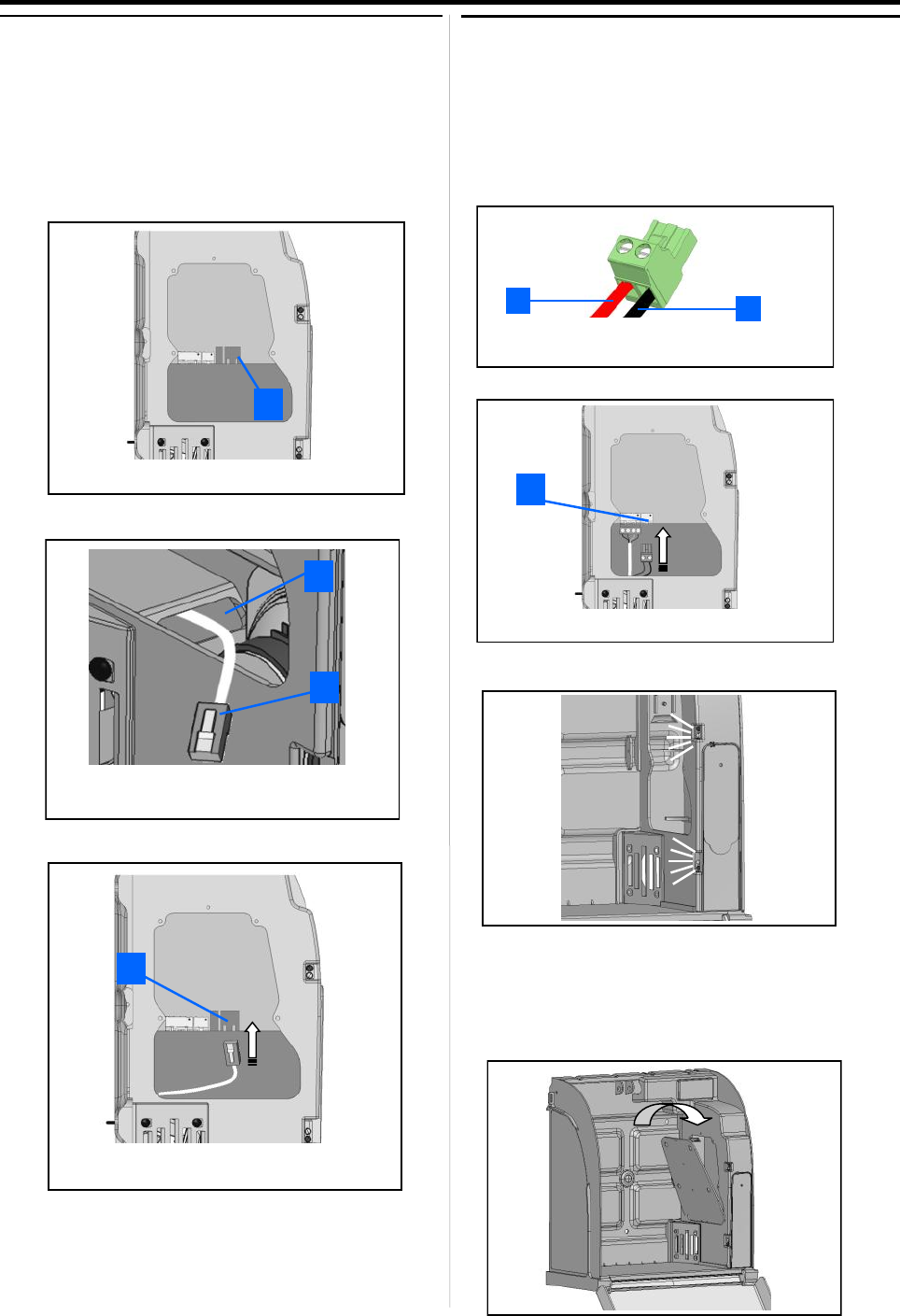
Ethernet network connection
( Except for 3G Option )
• The Aivia needs a Ethernet line in order to connect
to the Internet.
• Ethernet connection must be done in 10BaseT or
100BaseTX, using CAT5 or better cable.
• Access to the internet must be available through an
internet router.
• Slide the network cable through the cable passageway.
• Plug the cable into the connector.
• The indicator light on the RJ45 Connector displays its
status: "LINK/ACTIVITY".
2
1
1. Cable passageway.
2. RJ45 Plug (Network).
1. RJ45 Connector.
1
1. RJ45 Connector.
1
2
1
1. +24VDC Red Cable.
2. 0V Black Cable.
1. Power supply connector block.
1
Connect the power supply to the Aivia
• The Aivia must be powered using 24V DC, see the
"Power supply" section.
• Slide the power supply cables through the cable
passageway.
• Connect the cables on the connector block, making
sure to respect their polarity.
• Plug the connector block on the board.
• Check the power supply to the Aivia by verifying that
the white indicators are illuminated.
• If your Aivia must be configured, please see the
configuration section, before continuing.
• To close the Maintenance access door, clip it back in
place by inserting the lower part first. Then screw it on
using a Philips screwdriver.
9
Installation
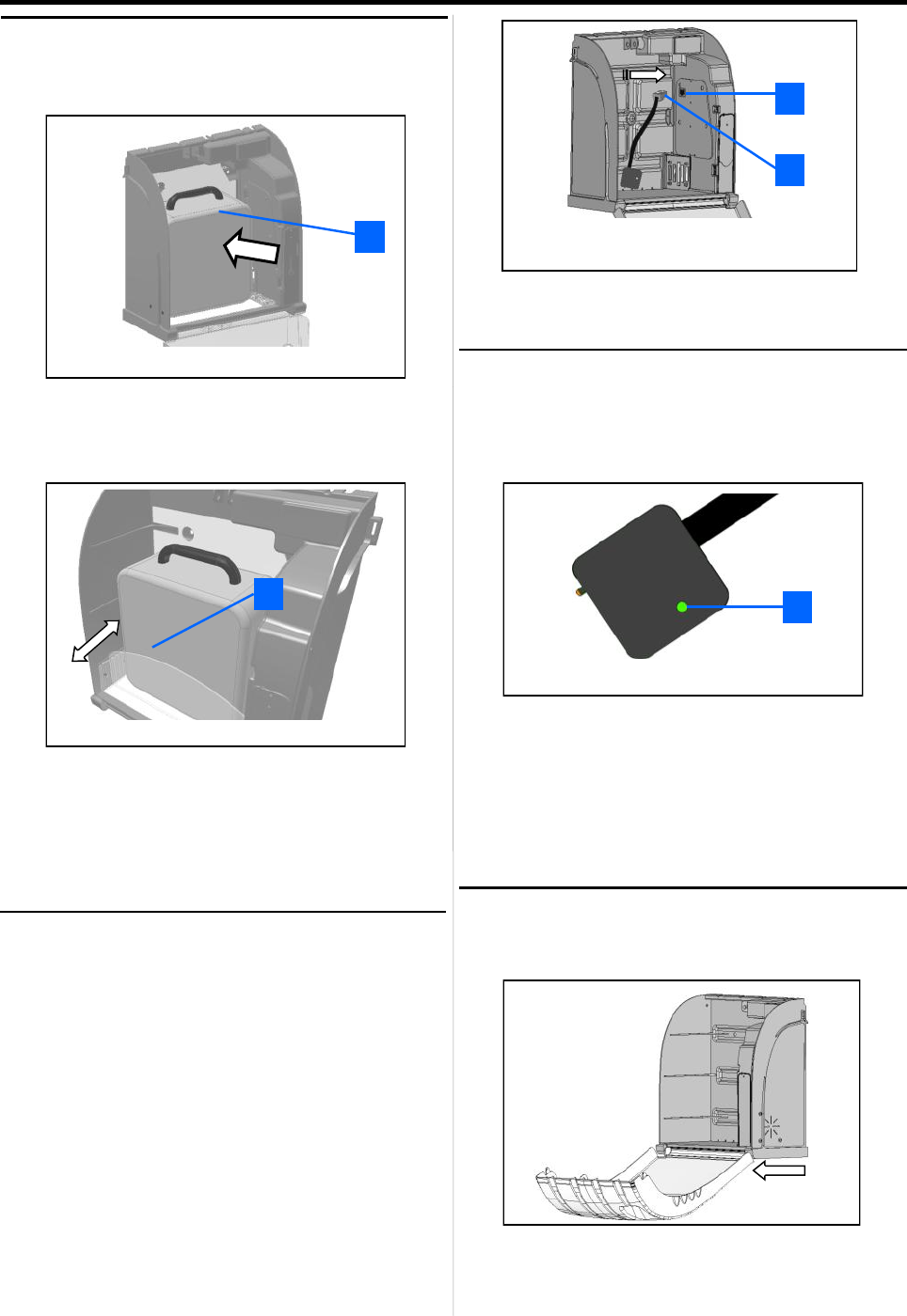
AED Status sensor installation
• The AED Status sensor requires that the AED and its
status indicator be operational in order to correctly check
the operational status of the indicator. Please check your
AED instructions if needed.
• Affix the adhesive base on the AED using the A-MICD
film.
• Please make sure you correctly defined your AED
model in the Configuration section.
• If your model is set to "blank", your sensor does not
need calibration. In this case, it will only check for
temperature and AED presence.
1. AED Status sensor RJ45 Connector.
2. AED Status sensor RJ45 jack.
1
2
AED Status sensor calibration
• During the initial installation, the AED status sensor must
be calibrated.
• Connect the AED Status sensor on the RJ45 plug.
• Put the AED Status sensor on its base as soon as it
blinks green/red.
• The indicator will light orange so as to signal that the
sensor is being calibrated.
• Once the AED status sensor is calibrated, the indicator
will light green, indicating that the AED is OK.
1. AED Status sensor indicator.
1
Closing the Aivia door
• Close the Aivia door. Be sure to first pull the door
towards you before shutting the door.
• Ensure correct operation by checking the LCD screen.
Diagnostic information about the LCD screen is available
in the section "Diagnosis/Troubleshooting".
• The AED Status sensor needs first to be connected to
the base.
Setting up the defibrillator
• Place the defibrillator to the bottom of the AIVIA.
• Efficiency of the heater is ensured by the contact of the
defibrillator with the rear of the enclosure.
• Adjust the position of the wedge to hold the AED in
contact with the heater.
1. Slide the AED to the rear of AIVIA
1
1. Slide the wedge in notches to hold the AED.
1

10
Contents
This section will allow you to configure your Aivia so that
it can be connected to the Internet and correctly monitor
your AED.
330
Configuration
Closing the Aivia
If you want to close your Aivia case during configuration,
report to the section "Maintenance" in order to open it in
Maintenance mode for configuration.
11
Configuration
Setup the Aivia
• The Aivia must be connected to the Internet in order to
be able to send any information to the AIVIAnet server in
real-time..
• A blank USB Key, formatted in FAT16 or FAT32, is
needed to setup the Aivia.
• A computer running Windows XP or higher is needed to
launch the AiviaTech configuration software.*
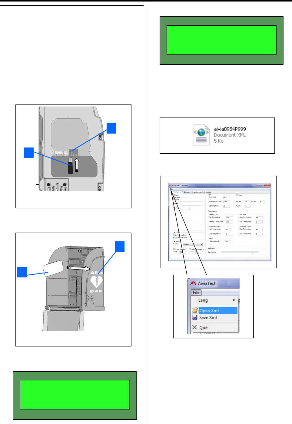
• Slide through your Maintenance badge, then open the
Aivia door. Remove the hatch as described in the
Maintenance section.
• Connect your USB key to the Aivia's USB jack.
• Slide slowly your "Maintenance" badge on the "AED"
logo, further to USB key’s detection by Aivia.
• The LCD screen will show ongoing action.
• Once the LCD screen displays the screen below :
• Your can retrieve the Aivia's USB Key, and connect it to
your computer.
Once the key is inserted in your computer, a file named
aiviaXXXXPXXX.xml appears. XXXXPXXX being the
Aivia’s unique serial number.
• You must now launch AiviaTech, open the XML file, and
edit the fields.
• Once the file is open, you can edit the available fields
based on your Aivia model.
1. USB Connector block.
2. USB Key.
2
1
1. "Maintenance" Badge.
2. Badge passage zone.
2
1
OPEN. MODE +20 C
MAINTENANCE
* The AiviaTech software is available on the AIVIAnet server in the "Download" section.
== FLASH.DR ERR ==
BACKUP RETRIEVED
12
Configuration
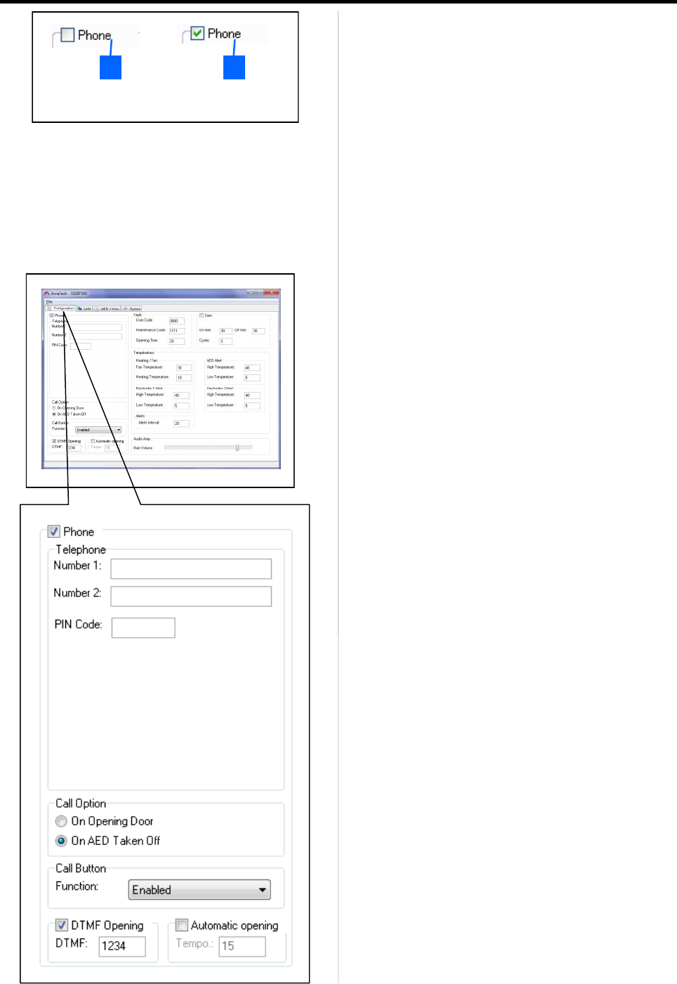
Grayed out zones [1] indicate an option you do not have
on your Aivia. Checkboxes, [2] Allow you to enable or
disable functions of your Aivia.
• You can edit all the available fields. We will now explain
their meanings.
Intercom:
• Disabling the Intercom will prevent the Aivia from
calling Emergencies services. In this case, all the
error codes linked to Intercom features will not be
displayed.
• Number 1: First phone number to be called in case of
emergencies or when the call button is pressed. This
phone number is mandatory.
• Number 2: If the first number cannot be reached, the
second phone number will be called.
• GSM–3G:
PIN Code : PIN Code from the SIM card inserted into the
Aivia.
• Call Option:
• On Opening Door: Call is emitted on door opening.
• On AED Taken Off: Call is emitted when the AED
sensor is taken off.
• Call Button:
The call button can work in three different ways :
• Disabled: Disabled, door opening mandatory.
• Enabled : One press calls emergencies.
• Enabled / Confirmation: Second press necessary in
the 10 following seconds to make the call.
• Automatic opening:
In seconds. Delay to the automatic unlocking of the Aivia
during a call.
• DTMF Code:
Enables the Aivia to be unlocked from a distance using
this code.
1. Greyed out zone.
2. Available checkbox.
2 1
13
Configuration
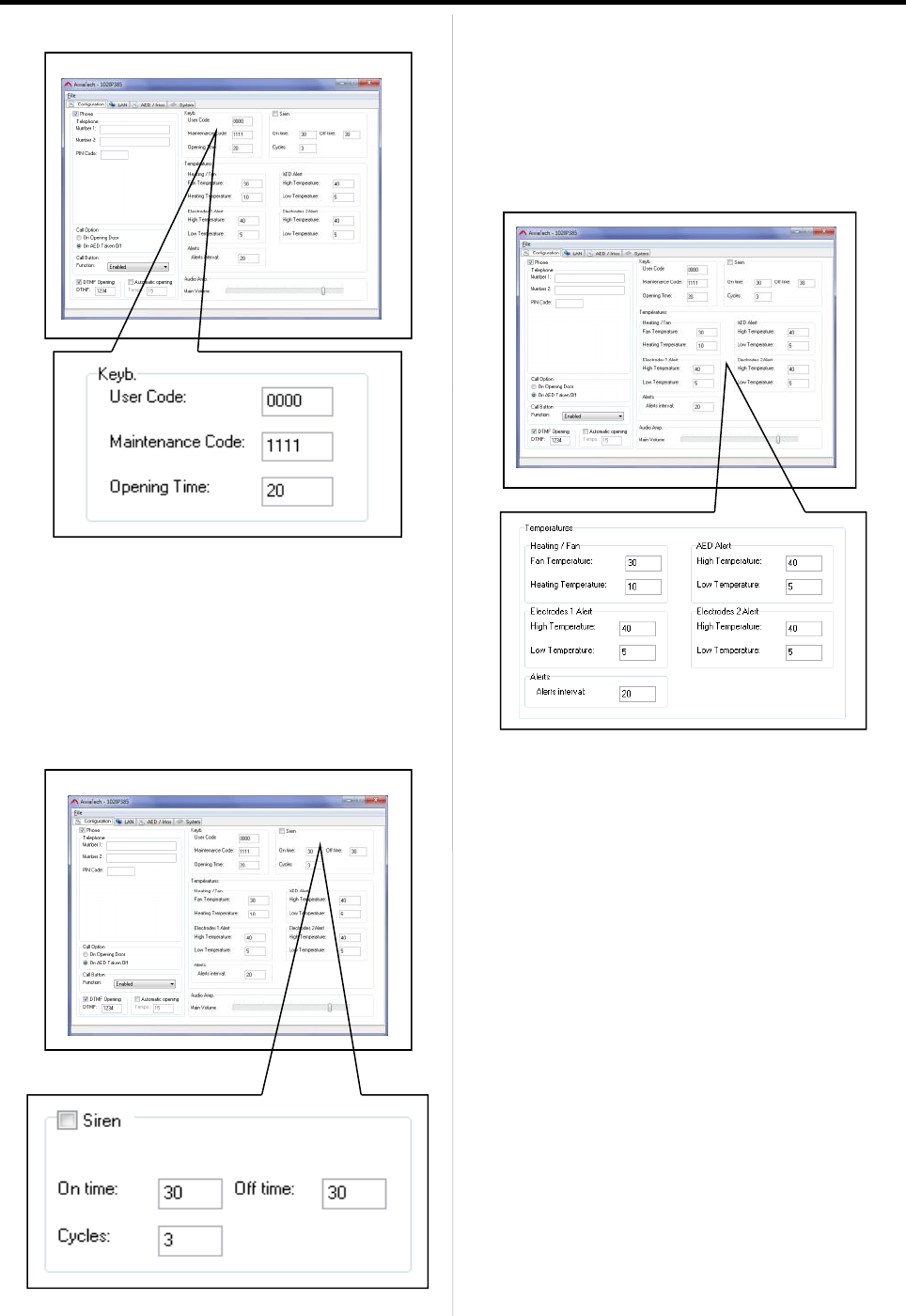
Keyboard:
• The user code unlocks the door and calls emergency
services.
• The Maintenance code allows the user to open and
setup the Aivia without making a phone call.
• The opening delay (in seconds) is the delay before the
Aivia re-locks itself (if unopened).
Audible Alarm:
• Siren disabling will still result in continuous led blinking
on opening.
• High Volume: Maximum volume output.
• On Time: The effective ringing time.
• Off Time: The time during which there is no ringing.
• Cycles: Number of "On Time" + "Off Time" cycles.
Temperatures:
• Heating / Fan:
These settings must allow the Aivia to heat or cool the
AED according to the Manufacturer’s specifications. 10°C
(50°F) Minimum gap between the Alert and setpoints).
• Fan Temperature: The fan switches on when the
temperature reaches this point.
• Heating Temperature: Heating switches on when the
temperature goes below this point.
• Alerts (All): See the AED Manufacturer’s manual to
know the extreme working temperatures.
• High Temperature: Temperature above which the
corresponding alert is signaled.
• Low Temperature: Temperature below which the
corresponding alert is signaled. The temperature alert is
also sent to the server.
14
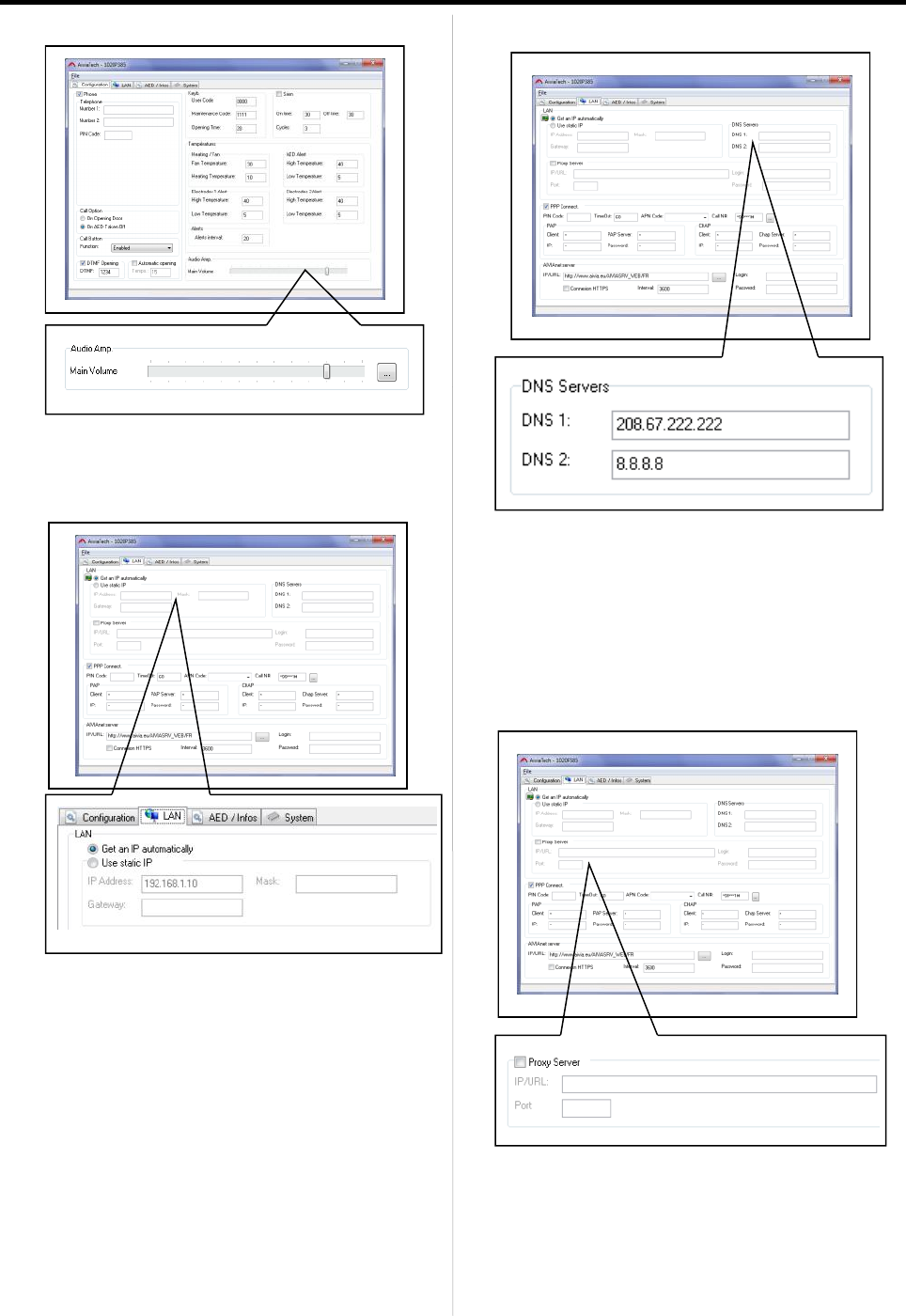
Audio Amp:
• General Aivia volume can be set here. The
button puts the default setting.
LAN:
You can get all your network parameters from your IT
service or SysAdmin.
• Get an IP automatically:
When activated, this option configures the Aivia in order
to automatically get an IP address using the DHCP
protocol. A DHCP server must be present and configured
on your network in order for this to work.
• IP Address: Unique IP address for the machine on the
network.
• Mask: Netmask, common to all machines on the
network.
• Gateway: Gateway IP address (router).
Configuration
DNS Servers:
• If no IP address is entered and the default IP
configuration is activated, the Aivia will attempt to reach
the DNS servers using the automatic Aivia configuration.
(DHCP).
• DNS 1: Primary DNS IP address.
• DNS 2: Secondary DNS IP address.
Proxy Server:
• If a proxy server is necessary to establish the
connection, it must be set up here using its IP or URL,
and its port.
• IP/URL: Proxy’s IP address or hostname.
• Port: Proxy server listening port.
15
Configuration
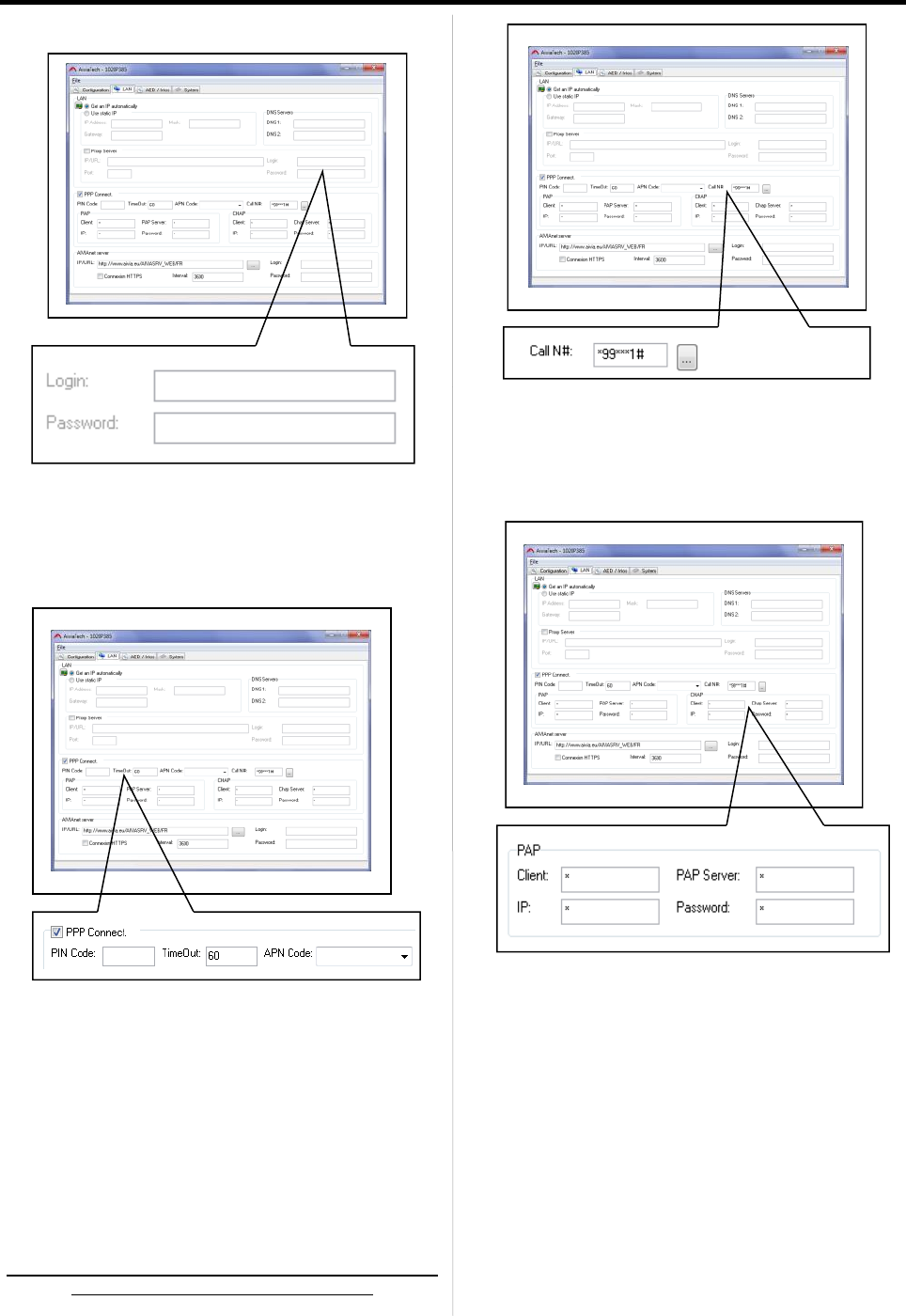
• If the proxy server has a authentication system, login
and password must be entered here.
PPP Connection:
• Only available in case of a 3G Aivia. This checkbox
must not be checked if the Aivia is connected to the
internet using an Ethernet cable.
• PIN Code: PIN Code of the inserted SIM card.
• TimeOut: Delay before shutting down the 3G
connection.
• APN Code: 3G Access Point Name. Given by the mobile
network operator.
In order to avoid fraudulent access attempts, the APN
code must have a private addressing.
• Call N#: 3G DATA mode call number. The button puts
the default setting.
• Max Data: Reserved for future use.
If a PAP or CHAP authentication exists, you must define
all the parameters here.
• Client: PAP/CHAP username.
• IP: IP Address of the server for which the authentication
is valid.
• PAP/CHAP Server: PAP/CHAP server IP address.
• Password: PAP/CHAP password.
* 3G Option only.
16
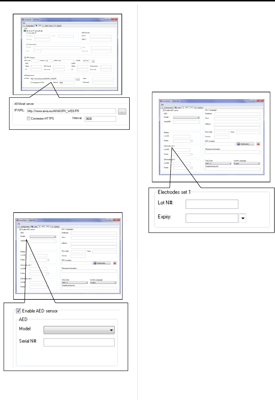
AIVIAnet Server:
• The AIVIAnet URL is entered here. The button puts the
default setting.
• HTTPS Connection: Reserved for future use.
• Interval: Defines the time interval in seconds between 2
Aivia contacts with the AIVIAnet server during its regular
activity. A shorter interval will result in more data
exchanges.
AED Sensor:
Configuration
• This field must be activated, except if your AED Status
sensor is deactivated. Select the AED model installed in
the drop-down list. If your AED does not appear in the list,
you must choose the blank line. In this case, only
presence and temperature will be monitored.
• Model: The AED Model located in the Aivia.
• Serial N#: S/N of the AED Present in the Aivia.
Electrodes set 1 & 2:
• Lot N#: Electrodes batch number.
• Expiry: Electrodes expiry date.
17
Configuration
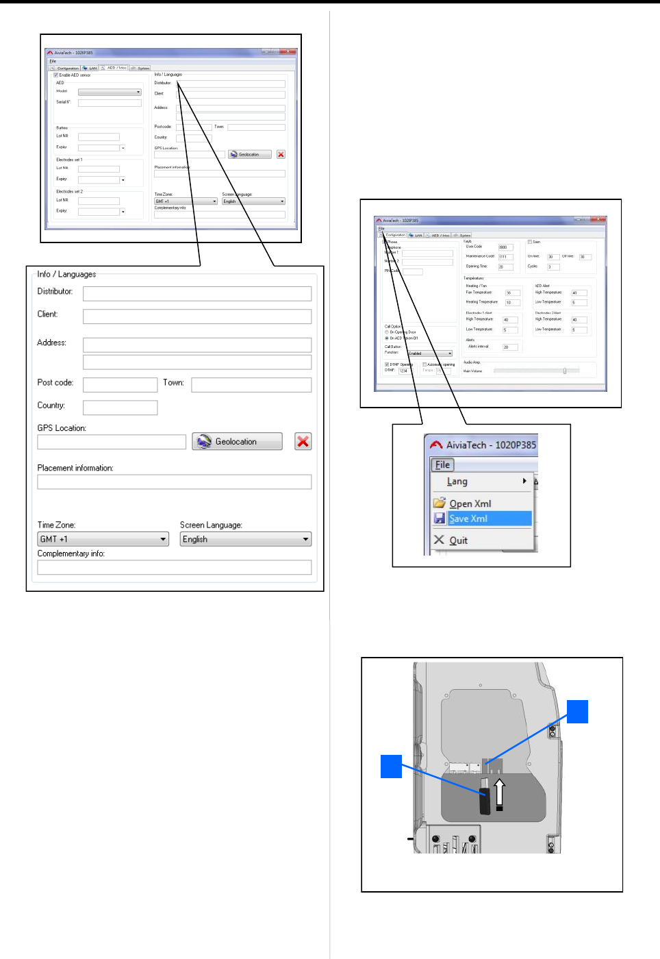
Info / Languages:
• Distributor: Aivia distributor.
• Client: Name of the customer.
• Address: Aivia installation address.
• Post Code: Area code.
• Country: Country where the Aivia is installed.
• GPS Location: GPS Coordinates.
• Placement information: Information on Aivia localization.
• Mail: Field active only when the Aivia is initialized.
• Time Zone: Aivia timetable.
• Screen language: LCD display language.
• Complementary info: Unrestricted field, for insertion of
additional information.
Once the file is edited, you must save it without changing
the filename, using the menu.
• Disconnect the USB key from the computer, then re-
insert it into the Aivia.
1. USB Connector block.
2. USB Key.
2
1
18
Configuration
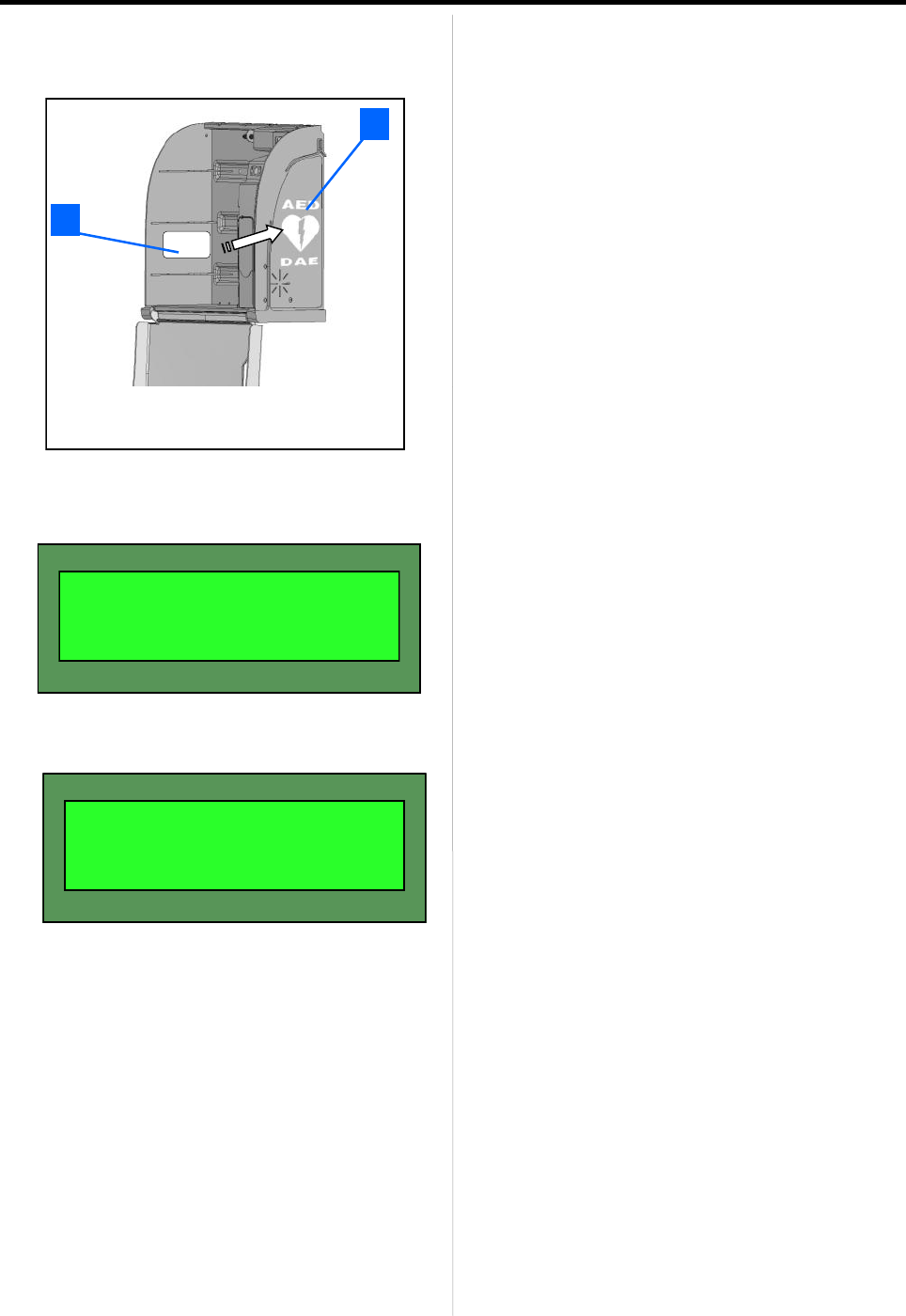
• Slowly slide your "Maintenance" badge across the
"AED" logo, further to enable the USB key’s detection by
the Aivia.
• The LCD Screen will then indicate the current action.
• The Aivia will then restart its network in order to take
into account the new parameters.
• Check on the AIVIAnet server that the new parameters
have been taken into account.
• Put the hatch back on the Aivia.
• Place the AED back in.
READ.CONF.FILE.
> UPD. CONF. SERV.
NETWORK RESTART
1. Maintenance badge.
2. Badge passage zone.
2
1

19
Contents
This section will enable you to use and maintain your Aivia.
330
Operation
20
Operation
Low light mode operation
• The Aivia is equipped with a light sensor.
When ambient light becomes insufficient, white indicators
blink to signal the Aivia’s position.
Heating option operation
• The heating option allows the AED to maintain its
operating temperature within predefined limits. In
extremely cold temperatures, it is worthwhile to check that
the alert temperature has not been signaled by the
flashing of the red indicators.
• The fan ensures proper heating ventilation of the Aivia.
In hot weather, it is worthwhile to check that the alert
temperature has not been signaled by the flashing of the
red indicators
AED removal Alert
• When the AED sensor is removed, flashing red lights
give a visual warning.
• An audible alarm will sound for about 3 minutes.
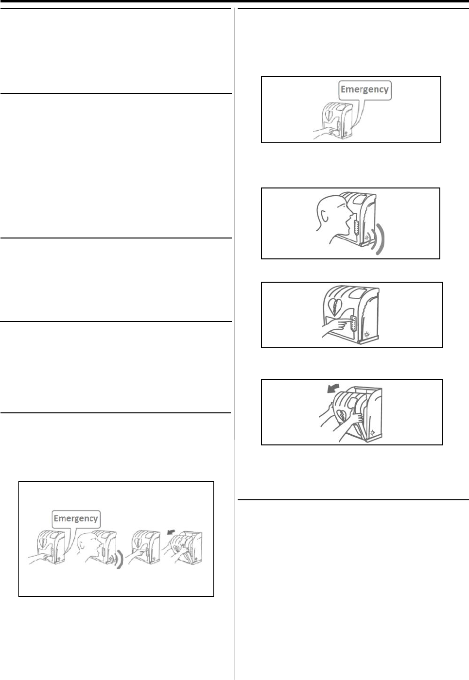
Using the Aivia
If you witness an incident requiring an AED.
• Contact emergency services.
Push the call button.
• Speak using a clear and loud voice, describe the
situation and make sure to precise the location of the
incident.
• Type the user code to unlock the Aivia.
• Open the Aivia door by pulling on it.
Visual alert is given by the blinking of the red indicators.
• Take the AED out.
• Go to the victim.
• Switch the AED on.
• Follow the AED’s instructions.
Pictograms
• The sequence printed on the AIVIA door indicates the
procedure to follow in case of emergency.
• Never cover these operating instructions.
After using the defibrillator
• Do not place the defibrillator back inside the AIVIA
before reactivating it.
• Follow the instructions in the defibrillator’s manual to
reset it for use.
• The manufacturer may be able to help reactivate the
defibrillator. Please feel free to contact them.
• After reactivating the defibrillator, replace it inside the
AIVIA using the instructions in the section "Setting up the
defibrillator".
• Replace the seal using the instructions in the section
"Installing a seal".
Temperature alerts:
• The temperature alert, signaled by 4 repeated flashings
of the door closed red indicators is triggered when the
temperature drops below the minimum defined
temperature, or over the maximum defined temperature.

21
Contents
This section will enable you to carry out the different
Maintenance operations on your Aivia
330
Maintenance
22
Maintenance
OPEN. MODE +20C
MAINTENANCE
Opening the Aivia in maintenance mode
• When the Aivia is closed, slide your maintenance badge
across the badge passage zone, or type your
maintenance code.
• Open the Aivia by pulling the door.
• The LCD Screen will then confirm the opening in
maintenance mode.
1. Maintenance badge.
2. Badge passage zone.
2. Aivia Keyboard.
1
3
2
Hatch opening and closing
• To open the Maintenance hatch, removed the access
door fixing screw using a Philips screwdriver, and then,
pull it from the top.
• In order to close the maintenance access door, put it
back by inserting the lower part first.
Then, screw the access door back using a Philips
screwdriver.
1
2
1. Hatch fixing screw.
2. Electronics access hatch.

23
Maintenance
Shutting down the Aivia
The Aivia must be able to connect to the AIVIAnet
server in order to signal its shutting down.
• Your Aivia must be opened in Maintenance mode.
• Cut off the 24 DC PSU.
Type the shutdown code on the Aivia keyboard and
validate it, or slide your "ARRET/Shutdown" badge across
the badge passage zone :
• Wait for the LEDs to switch off.
0 0
AED Status sensor maintenance mode
calibration.
• In order to calibrate the AED Status sensor using the
keyboard, it must be connected to the Aivia and installed
on its base.
• Your Aivia must be opened in Maintenance mode.
• Please type the AED Status sensor calibration code,
then validate:
• The AED Status sensor will now calibrate itself.
3 0 0
AED Status sensor LED indicator
• The AED Status sensor displays its status using the
LED screen situated on top of the sensor. Here are the
different status settings.
• Fast red/green flashing: Starting, 4 second countdown
to calibration.
• Orange flashing: Sensor is to be calibrated.
• Orange light: Sensor is calibrating.
• Red flashing: AED anomaly detected, waiting for
confirmation.
• Red light: AED anomaly confirmed..
• Green blinking: AED Correct status detected, waiting
for confirmation.
• Green light: AED correct status confirmed.
• Red fast blinking: Firmware update in progress do not
unplug the sensor.
Aivia maintenance
• Wash the Aivia surfaces using a wet cloth. Wipe the
Aivia with a clean & dry cloth. Do not use washing or
chemical products, they could damage it.
• Do not rub the Aivia with any hard object, you might
damage it permanently or scratch it.
• Do not use a high pressure cleaner.

24
Notes

25
Contents
This section will enable you to diagnose and solve any
problems related to the Aivia.
330
Diagnosis / Troubleshooting

26
Diagnosis / Troubleshooting
LCD Display status
• If your Aivia’s door is closed, it will display a screen as shown below:
• ALIM: Information about the Aivia power supply:
- OK Means PSU is OK.
- —Means PSU is down and the Aivia is operating on batteries.
• AED : Information about the AED and its sensor:
- OK Means the AED is present, functioning, and the sensor is operating correctly.
- HS Indicates the AED is present, and the sensor is detecting a failure.
- — Indicates the AED is not correctly linked to the sensor.
- ?? Indicates a malfunction, please contact your distributor.
- 1C Indicates the AED status sensor is to be calibrated.
- TT Indicates the AED status sensor is unplugged or non-operating, check the AED status sensor connection,
contact your partner if the problem persists.
HTTP: This part of the screen indicates the status of the internet connection:
- OK indicates the last transaction was OK.
- ok indicates an invalid answer from the server.
- — indicates a connection default.
- cx indicates a connection is in progress.
- All the other states indicate a transmission is in progress.
• T+25:OK This part of the screen indicates the AED temperature, and the status of the temperature sensor:
- T+25 indicates the temperature (Celsius degrees).
- T- — indicates the temperature sensor is disabled.
- T-HS indicates the temperature sensor is out of order. Contact your distributor.
- T??? Indicates a malfunction, contact your distributor.
- OK Indicates the temperature is in the Aivia defined temperature ranges.
- HS Indicates the temperature is out of range. In this case check the Defibrillator status with your distributor.
- ?? Indicates a malfunction, in this case, contact your distributor.
- — indicates the temperature sensor is deactivated.
PWR: OK HTTP:OK
AED : OK T+25 :OK
27
Diagnosis / Troubleshooting
• White indicators do not light up when the Aivia is switched on.
1. Check the wiring polarity.
2. Check the power supply cable connection.
3. Check the voltage at the connector block.
4. Check the insertion of the connector block.
5. Contact your distributor.
• White indicators do not flash in low light mode.
1. Check the Aivia power supply.
2. Contact your distributor.
• Red indicators do not flash when the AED sensor is removed.
1. Check the Aivia power supply.
2. Contact your distributor.
• Alarm does not sound when the AED sensor is removed.
1. Check for the alarm option on the Aivia identification label.
2. Check the Aivia power supply.
3. Contact your distributor.
• I do not know my maintenance/user code.
. 1. Shut down the Aivia power supply.
2. Place your "ARRET/Shutdown" badge on the Aivia right side.
3. Open the Aivia.
4. Switch on the Aivia, the white indicators will light up.
5. Set the User/Maintenance code, as described in the "Setting up the Aivia" section.
6. Close the Aivia.
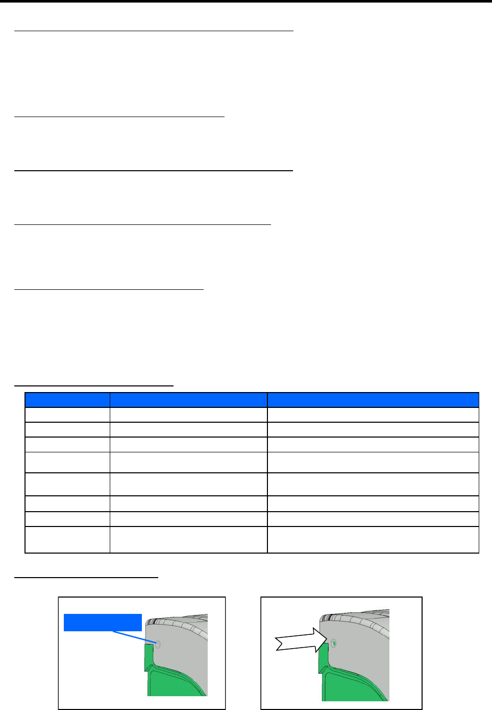
• Red indicators flash in a sequence.
• Aivia motorization doesn’t work.
Removed the cap the Aivia door, and push back the door blocking axle with a narrow point.
Number of blinking's Cause Solution
1 Failing memory Contact your distributor.
2 Parameters lost Set-up the Aivia again
3 Temperature sensor breakdown Contact your partner.
4 Alert temperature reached Check the AED is working, if necessary, contact your distributor
5 AED absence Check for AED presence and if the AED Status sensor is on its
base.
6 AED Out of order Check the AED status, if needed, contact your distributor
7 GSM-3G Phone and data problem Check your reception level, PIN code.
Continuous Aivia case opening Check the AED operates correctly, and that all the accessories
are present if necessary, contact your distributor.
Cap

28
Contents
The information for the Electrical installation and
Electrical Specifications can be found here.
330
Electrical installation / Specifications

29
Electrical Installation
SELV Wiring:
• Type U1000R2V. 2 insulated jacketed conductors,
15AWG (1.5 mm²) area, 33 feet (10 meters) maximum
length.
• Use red or maroon colour cable for the +24V line.
• Use black or grey colour cable for the 0V line.
POWER SUPPLY unit
SELV Wiring
Mains Power
100/240VAC
50/60Hz
Power Supply
24VDC/3A
CLASS II
Power Supply Unit
Must be located outside the AIVIA, never installed
inside the AIVIA.
•The power supply block must include:
• A 10A/30mA residual current device, serving both to
protect and disconnect the hardware.
• A SELV or equivalent 24VDC +-2% / 3A Class II,
and IEC 60950-1 conform.
• The cable connecting the residual current device
and the power supply must be a section of 15AWG
(1,5 mm²).
• The main connection must include the primary phase,
and neutral.
• The maximum full load secondary voltage drop must not
exceed 2%, or 23.5V at the AIVIA terminal.
• The power block must be dust and waterproof, and
ventilated**.
• Wires must be held against themselves by a collar
at the nearest of the holding terminals. The power
block wiring must conform to standards in force in
the country of use.
* Recommended power supply: Meanwell DR100-24.
** Natural or forced convection depending on the environment and
thermal characteristics at maximum load.
30
Specifications
• Operating temperatures and humidity levels:
Minimum: -4°F (-20°C) without wind-chill.
Maximum: 104°F (40°C).
Relative humidity: 95% without condensation.
• Temperature alerts:
Low temperature alert: 41°F (5°C) by default.
High temperature alert: 104°F (40°C) by default.
• Heating:
Heating setpoint: 50°F (10°C) by default.
Fan setpoint: 86°F (30°C) by default.
• Maximum weight capacity: 11lb (5kg).
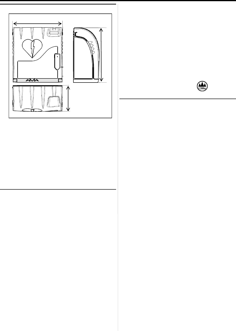
• Maximum altitude: 6,562 ft (2,000m).
Compliance
IEC 60950-1:2005+A1:2009
EN 60950-1:2006 (Second Edition) +A11:2009 +A1:2010
+A12:2011
UL 60950-1:2007 R12.11
CAN/CSA-C22.2 No.60950-1-07+A1:2011
EN 301 489-3 : 2013
EN 301 489-24 : 2010
EN 50364 : 2010
EN 300 330-2 V1.5.1
EN 301 908 1 V5.2.1 (2011-05)
FCC 47 CFR PART 15: 2014
RSS-Gen et RSS-210
This device contains:
FCC ID: SZ4-3XX090601
IC ID: 11067A-3XX090601
3G device contains:
FCC ID: N7NQ2698
IC ID: 2417C-Q2698
Federal Communications Commission (FCC) Compliance Statement:
This device complies with part 15 of the FCC Rules. Operation is subject to
the following two conditions:
(1) This device may not cause harmful interference, and(2) This device must
accept any interference received, including interference that may cause
undesired operation.
Industry Canada (IC) Compliance Statement:
This device complies with Industry Canada licence-exempt RSS standard(s).
Operation is subject to the following two conditions:
(1) this device may not cause interference, and (2) this device must accept
any interference, including interference that may cause undesired operation
of the device.
Mechanical properties
• Weight:
- U2A330-XX111: 3.4 kg (7.49 lb).
• Materials:
- Door: Polycarbonate.
- Frame: ABS.
- Bracket: ABS.
- Access door: ABS.
15 1/4"
(388 mm)
7 15/16"
(201 mm)
16 5/8" (423 mm)
Technical properties
• Power supply:
- SELV 24VDC +-2% / 3A, IEC 60950-1 conform.
• Electrical consumption:
- U2A330-XX111:
Minimum: 200 mA.
Maximum: 2500 mA.
Sound level: 90– 105 dB / 39 in (1m).
• Battery autonomy: 2 Hours 30.

31
Notes

32
www.hd1py.com
contact@hd1py.com
2015-07-09
*A-MIS330-US-214*