Packet Power P5EMB1 Ethernet Gateway User Manual Manual
Packet Power Ethernet Gateway Manual
Manual
©2014PacketPowerLLCwww.packetpower.comEM31.2 1
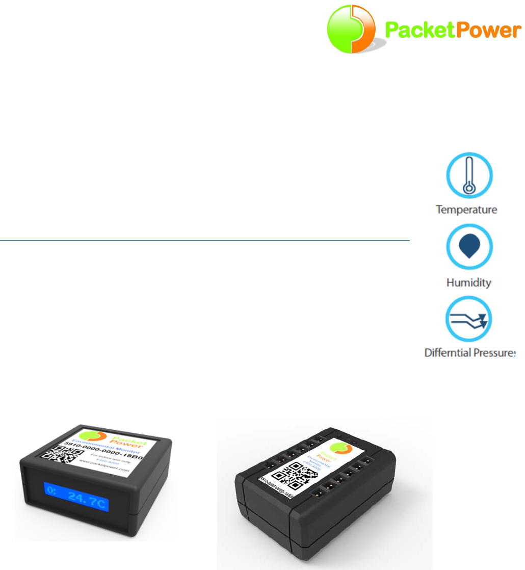
EnvironmentalMonitorV3
InstallationManual

©2014PacketPowerLLCwww.packetpower.comEM31.2 2
IndicatesaPOTENTIALHAZARD.Consultdocumentationcarefully.
CAUTION
Read all instructions carefully prior to installation.
No field-serviceable parts. Do not attempt to disassemble the product.
Store in a clean, dry location. Clean with a dry cloth.
Intended for indoor use only, do not install in a wet location.
Adhere to all local electrical codes and guidelines.
Failure to use the product in the specified manner may lead to injury or death and
damage to equipment.

©2014PacketPowerLLCwww.packetpower.comEM31.2 3
REGULATORY INFORMATION
This product has been certified to meet the following requirements:
UL / ANSI standards 61010-1,Second Edition, Dated July 12, 2004 with revisions through and including October 28,
2008
CAN/CSA-C22.2 No. 61010-1, second edition, including Amendment 1, or a later version of the same standard
incorporating the same level of testing requirements.
Council Directive 2006/95/EC (December 12, 2006) on Low Voltage Equipment Safety; IEC 61010-1:2001 (Second
Edition) and EN 61010-1:2001 (Second Edition)
Council Directive 1999/05/EC - European Union (EU) Radio & Telecommunications Terminal Equipment Directive
(R&TTE) ETSI EN 300 220-2, Issued:2006/04/01 and ETSI EN 301 489-3, Issued:2002/08/01 V1.4.1
Council Directive 2004/108/EC (December 15, 2004) on Electromagnetic Compatibility CENELEC EN 61326-1
Issued:2006/05/01; IEC 61326-1:2005;:1997 –
AS/NZS 4268: 2008
The products variously carry the cULus, ETL, IC, FCC and CE marks and are also eligible to carry the ICASA mark.
Class B Device Statement / FCC Regulations:
Section 15.105(a) of the FCC Rules: This equipment has been tested and found to comply with the limits for a Class B digital
device, pursuant to part 15 of the FCC Rules. These limits are designed to provide reasonable protection against harmful
interference when the equipment is operated in a commercial environment. This equipment generates, uses, and can radiate radio
frequency energy and, if not installed and used in accordance with the instruction manual, may cause harmful interference to radio
communications.
Section 15.19 of the FCC Rules: This device complies with part 15 of the FCC Rules. Operation is subject to the following two
conditions: (1) This device may not cause harmful interference, and (2) this device must accept any interference received, including
interference that may cause undesired operation.
Pursuant to Part 15.21 of the FCC Rules, any changes or modifications to this product not expressly approved by Packet Power
LLC might cause harmful interference and void the FCC authorization to operate this product.
Pursuant to part 2.1091c of the FCC rules device is categorically excluded from routine RF Exposure regulations.
Industry Canada (IC) Compliance Statement
This device complies with Industry Canada license-exempt RSS standard(s). Operation is subject to the following two conditions:
(1) This device may not cause interference, and (2) this device must accept any interference, including interference that may cause
undesired operation of the device.
Under Industry Canada regulations, this radio transmitter may only operate using an antenna of a type and maximum (or lesser)
gain approved for the transmitter by Industry Canada. To reduce potential radio interference to other users, the antenna type and
its gain should be so chosen that the equivalent isotropically radiated power (e.i.r.p.) is not more than that necessary for successful
communication.
Per section RSS-102, 2.5 of Industry Canada regulations, this device is categorically excluded from Routine Evaluation Limits.
Industrie Canada (IC) Déclaration de conformité
Le présent appareil est conforme aux CNR d'Industrie Canada applicables aux appareils radio exempts de licence. L'exploitation
est autorisée aux deux conditions suivantes : (1) l'appareil ne doit pas produire de brouillage, et (2) l'utilisateur de l'appareil doit
accepter tout brouillage radioélectrique subi, même si le brouillage est susceptible d'en compromettre le fonctionnement.
Conformément à la réglementation d'Industrie Canada, le présent émetteur radio peut fonctionner avec une antenne d'un type et
d'un gain maximal (ou inférieur) approuvé pour l'émetteur par Industrie Canada. Dans le but de réduire les risques de brouillage
radioélectrique à l'intention des autres utilisateurs, il faut choisir le type d'antenne et son gain de sorte que la puissance iposotrope
rayonnée équivalente (p.i.r.e.) ne dépasse pas l'intensité nécessaire à l'établissement d'une communication satisfaisante.

©2014PacketPowerLLCwww.packetpower.comEM31.2 4
CONTENTS
OVERVIEW.................................................................................................................................................5
DEVICEINSTALLATION..............................................................................................................................6
DEVICEPLACEMENT..................................................................................................................................7
TEMPERATUREPROBEKITS....................................................................................................................12
DIFFERENTIALPRESSURESENSING.........................................................................................................16
HUMIDITYSENSING................................................................................................................................16
DRYCONTACTSENSING..........................................................................................................................17
DISPLAYANDCOMMUNICATIONS..........................................................................................................17
NETWORK/GATEWAYINTERFACE.........................................................................................................18
TECHNICALSPECIFICATIONS...................................................................................................................20
©2014PacketPowerLLCwww.packetpower.comEM31.2 5
OVERVIEW
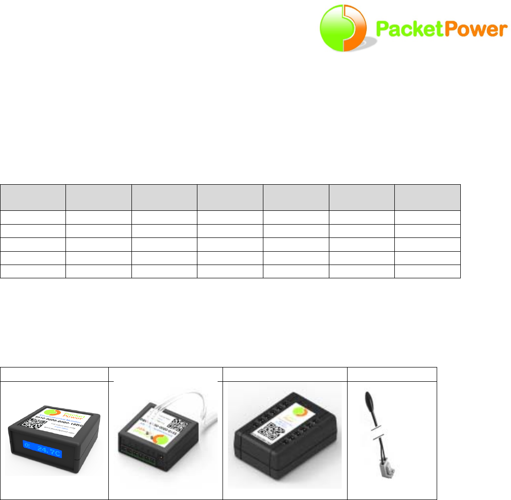
ThePacketPowerEnvironmentalMonitorprovidesaneasyto‐implementwirelessenvironmental
monitoringsolution.Eachmonitorwillaccommodatesixtotwelveexternaltemperatureordrycontact
inputsandalsomayhavehumidityordifferentialpressuresensing(seemodelreferencesinthechart
below).
ENVIRONMENTALMONITORV3MODELS
ModelMax.ProbesRelative
Humidity
Differential
Pressure
ACPower BatteryPowerMounting
Bracket
E306‐0000 6NN Y N Optional
E306‐H000 6NN Y N Optional
E306‐P000 6YY Y N Optional
E312‐0000 12NNOptional Y Y
E312‐H000 12YNOptional Y Y
1INTERNALTEMPERATUREPROBE:Themonitorincludesaninternaltemperaturesensorlocatedinsidethemonitor.Thisisnot
intendedtoprovideanaccurateambienttemperaturebutratherareferencetemperaturethatmaybeslightlyhigherthanthe
ambienttemperature.
E306-0000 E306-P000E312-H000 Temp. Probes
©2014PacketPowerLLCwww.packetpower.comEM31.2 6
DEVICEINSTALLATION
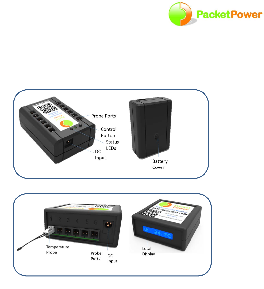
Dependingonthemodelofenvironmentalmonitor,youwillhaveeithersixor12availableprobeports
fortemperatureprobesordrycontactsensors(probesareuniversal).Itissuggestedthatyoulabel
probestoassistinidentificationoftheplacementifprobesarenotprovidedpre‐labelled.Probes
suppliedinkitswillbepre‐labelled.
E306Monitor
E312Monitor

©2014PacketPowerLLCwww.packetpower.comEM31.2 7
POWERSUPPLIES:Thesixchannelmodelsrequiresa5VDCsourcewhichcanbeprovidedfromthe
universalpowersupplycontainingplugtypesformostregionswhichisincludedwiththedevice.A5
VDCPoweroverEthernet(PoE)sourcecanalsobeused.
The12channelbatterymodelsrequire2xAAbatterieswhichwillprovideagreaterthantwoyear
batterylifeundertypicalapplications.Thismodelcanalsobesuppliedwith5VDCdirectlyfromanAC
source.
USINGAPOE(POWEROVERETHERNET)SOURCE:TheE306andE312andthe
GatewaymodulecanbepoweredbyaPoEsourceusingastandardPoE
splitter.ThePoEsourceshouldhavea5VDCoutput(not12VDC).The
monitorandGatewayconsume0.5Wand0.7Wrespectivelymakingitideal
forPoEapplications.
DEVICEPLACEMENT
DEVICEPLACEMENT
Donotlocatethemonitoringnodeinsideofafully
enclosedmetalstructure
Keepatleast2‐4”(5‐10cm)awayfrommetallicsurfaces.
Usethemountingbracket(PN:MOUNT‐EGEM)tofacilitate
optimalmountingfortheE306Moduletokeepawayfrom
metalsurfaceslikethetopofservercabinets.
PoESplitter
E306MountingBracket(PNMOUNTEGEM)
©2014PacketPowerLLCwww.packetpower.comEM31.2 8
E312Mounting
Bracket
TheE312moduleincludesanothermountingbracket(shownbelow)thatcanbe
fastenedwithtiewraps,adhesivetabsorscrews.Usethesameprecautions
whenmountingthisdevice.
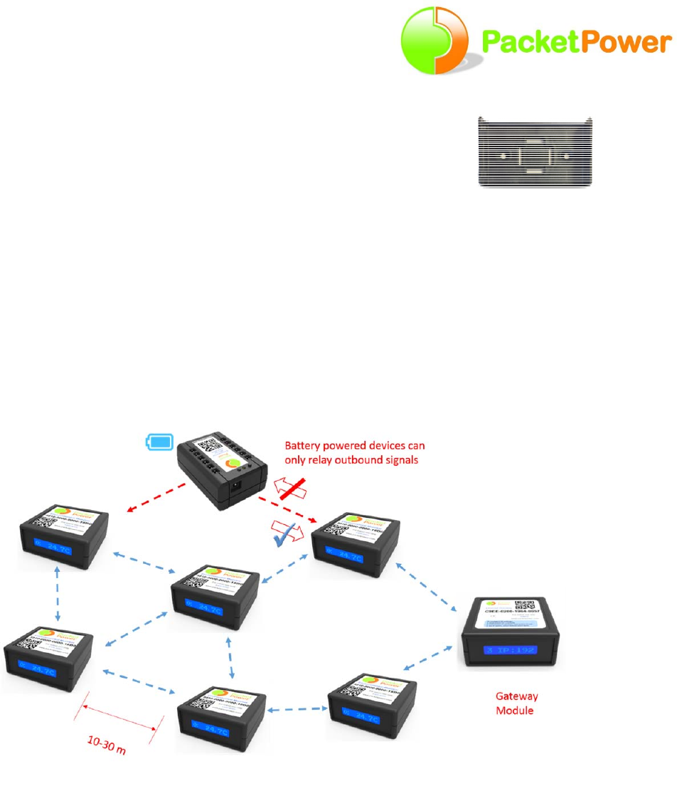
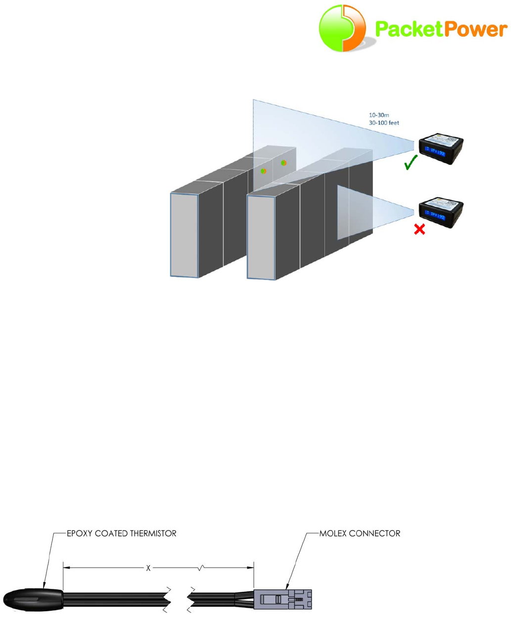
NODESPACINGANDRELAYFUNCTION:
Themonitoringnodesmustbewithin10to30meters
(30‐100feet)ofanothermonitoringnodeortheGatewaydevice.Thesignalwillberelayedthrough
adjacentnodestoformthebestpossibleradiopath.
Notethatwhenoperatingonbatterypower,theE312devicecanonlytransmitthroughnodesthatareAC
powered.Onbatterypowernodescannotrelaysignalsreceivedfromothernodes.
PacketPowerMeshNetwork
©2014PacketPowerLLCwww.packetpower.comEM31.2 9
Alwaysmountmonitorsat
thehighestpointthat
allowsanunobstructed
pathtoanothermonitoring
nodeorGateway.
TEMPERATUREPROBES
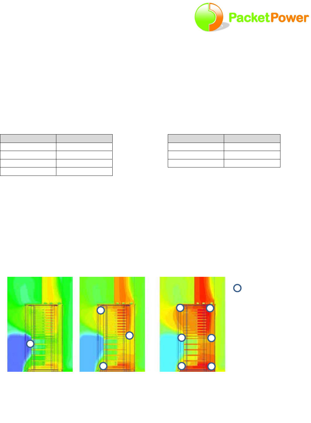
TEMPERATUREPROBES:Eachmonitorcanaccommodateuptosixortwelveexternaltemperature
probes.Temperatureprobesconsistofasmallepoxy‐coatedthermistorattheendofalightgaugewire.
Eachprobewirehasapluginconnectorthatcanbeinsertedintoanyoftheprobereceptacles.
Probesarealsoavailableaskitsthatallowonemonitoringdevicetomonitorthetemperatureatfrom
onetosixservercabinets.Asracksizesandconfigurationsandprobeplacementwillvaryonspecific
installation
consultthe
“
PROBE
LENGTH
CONFIGURA
TION
CHART
”for
suggested
placement.
©2014PacketPowerLLCwww.packetpower.comEM31.2 10
AVAILABLEPROBELENGTHS:Probesareavailablein1to4meterlengths.Ifalongerprobeleadlength
isrequiredextensioncablescanbeaddedtotheprobetoaccommodatetherequiredlength.
TEMPERATUREPROBES EXTENSIONCABLES
ModelLength(meters) ModelLength(meters)
TPP3‐001M1mTPP3‐X02M 2m
TPP3‐002M2mTPP3‐X04M 4m
TPP3‐003M3mTPP3‐X09M 9m
TPP3‐004M 4m
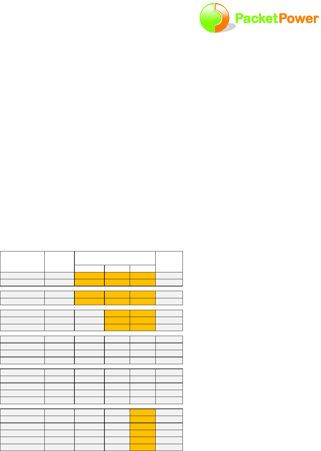
TEMPERATUREPROBEPLACEMENT:Idealtemperatureplacementisafunctionofracktype,appliance
type,airflowandspecificappliancelocationanddensity.Asageneralruletemperatureprobesare
placedontheintake(cool)orfrontsideoftherack.Thisistomonitorthetemperatureoftheinputair
flow.Theinputairismonitoredasitcanbecontrolledwherebytheoutputorrearairflowisafunction
ofthedeviceheatgenerationandinputairtemperatureandflow.Inhighdensityapplications,itis
recommendedtomonitorboththeinput(front)andoutput(rear)airflow.Thisallowsforidentification
of“hotspots”thatmayindicatedevicesareoperatinginexcessoftheirthermalratings.
TemperatureProbe
ProbePlacement
Low Density
Cabinet: 1
p
robe
p
er
Medium Density
Cabinet: 3
p
robes
p
er
High Density
Cabinet: 6
p
robes
Theabovediagramillustratessuggestedprobeplacementdependingonthethermaldensityof
thecabinet.
©2014PacketPowerLLCwww.packetpower.comEM31.2 11
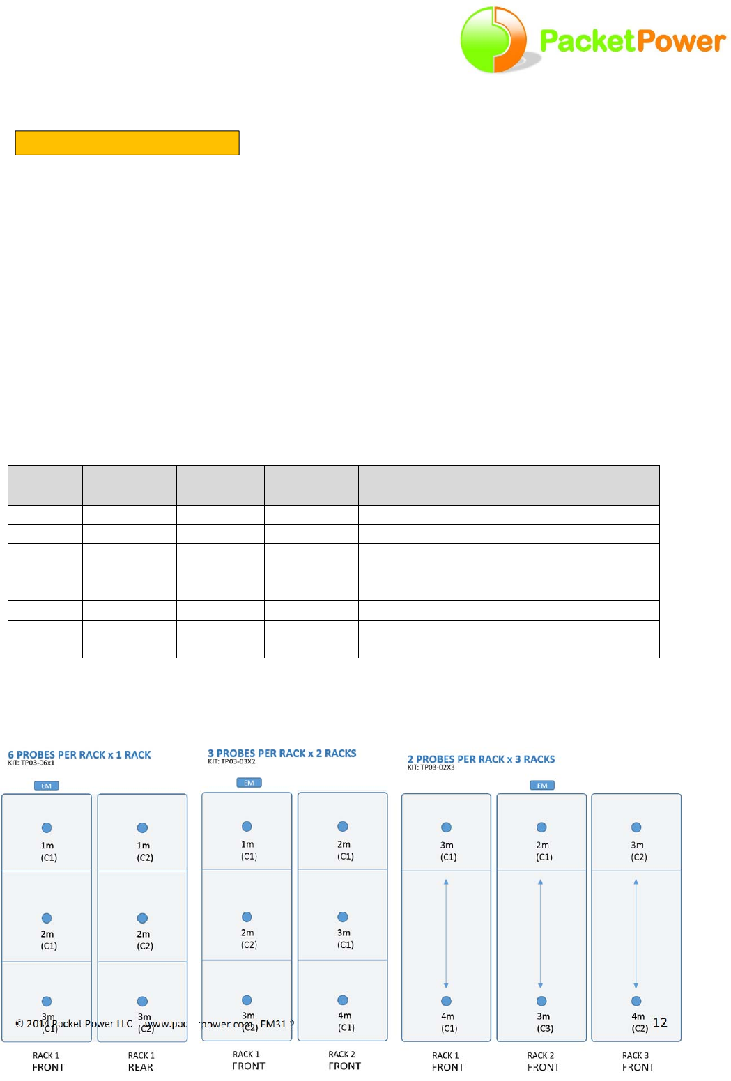
DETERMINGPROBELENGTH:Thechartbelow(PROBELENGTHCONFIGURATIONCHART)liststhecable
lengthsrequiredforatypical42‐48RUrack.Lengthsarelistedbyplacementlocations(i.e.top1/3,
middle1/3orbottomthirdsectionsoftherack).Probescanbepurchasedindividuallyoraskitsetsfor
monitoringonetosixrackspermonitor.
Thehighlightednumbersineachsectiondenotetheprobelengthsincludedwiththeprobekits.Probe
kitsprovidethesixprobesneededformonitoringonetosixcabinets.
Typicalcableroutingisalongtheinsideperimeteroftherackwiththecablesecuredusingwiretiesor
adhesivecabletabs.Itisassumedthatthemonitorwillbelocatedontheoutsidetopsectionofthe
centeroftheroofoftherack.
PROBELENGTHCONFIGURATION
CHART
Top MiddleBottom
11(Front) 2m 2m 3m x
1(Back) 2m 2m 3m x
2 1 2m 2m3m x
22m3m4mx
3 1 2m 3m 4m
22m2m3mx
32m3m4m
4 1 2m 3m 4m
22m2m3m x
32m3m4mx
43m4m4m
5 1 3m 4m 4m
22m3m4m
32m2m3mx
42m3m4m
53m4m4m
6 1 3m 4m 4m
22m3m4m
32m2m3mx
42m3m4mx
53m4m4m
63m4m5m
ProbePlacement(sectionof
cabinet)andLength(m)NumberofRacks
perMonitor Cabinet
Monitor
Location
©2014PacketPowerLLCwww.packetpower.comEM31.2 12
TEMPERATUREPROBEKITS
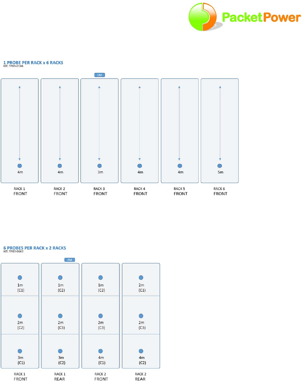
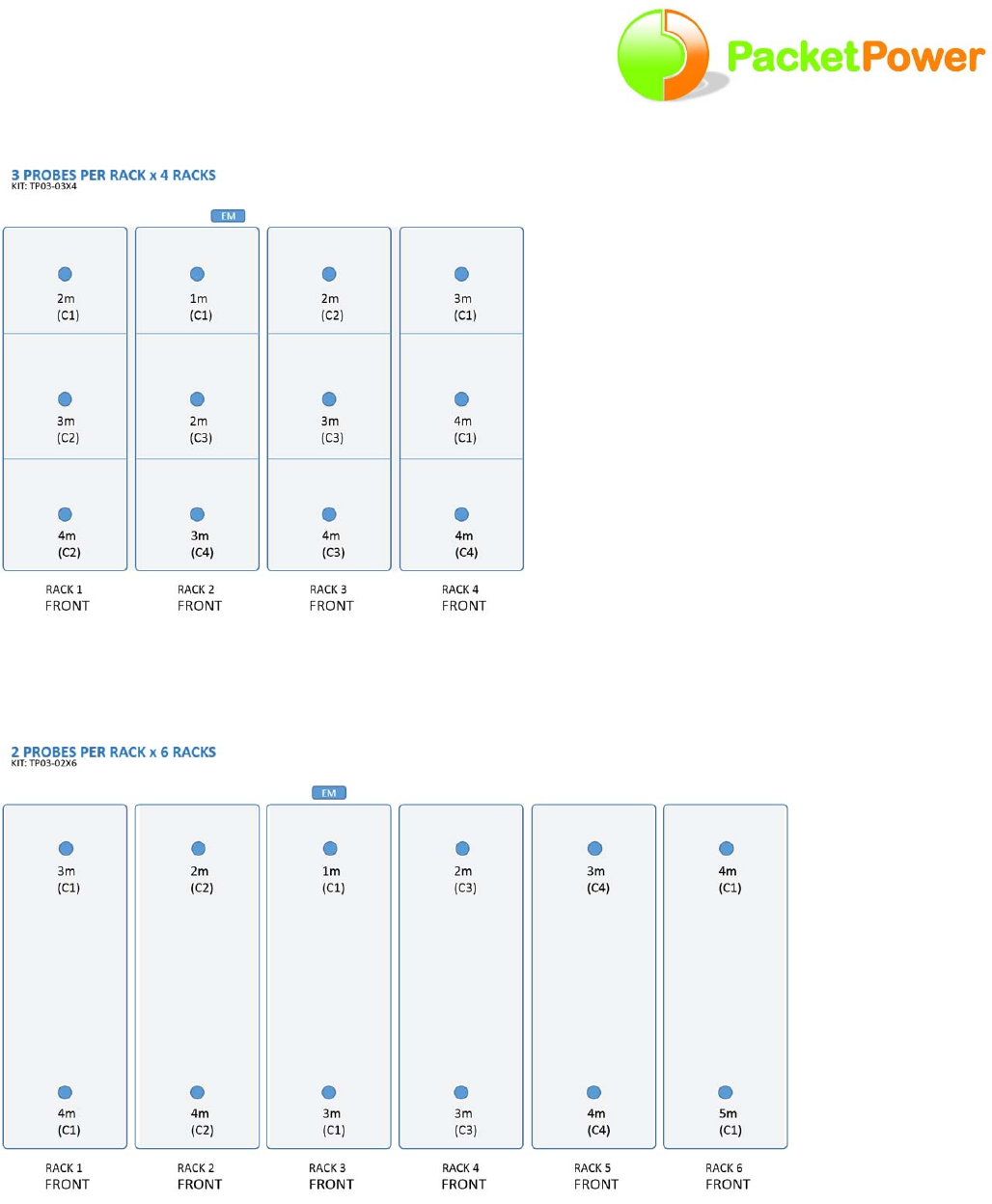
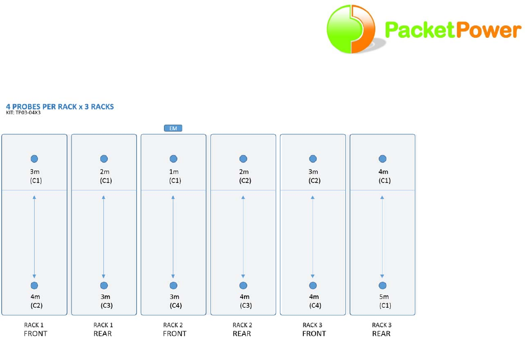
Temperatureprobeskitsarepreconfiguredtoprovidethespecificprobelengthsrequiredformonitoring
onetosixrackswithbetweenoneandsixprobesperrack.Probesarelabelledtoindicatetheirlength
andlocation.Consultthediagramsbelowforyourspecificcabinet.
TEMPERATUREPROBEKITS
Model
Probesper
Rack
Racksper
Monitor
TotalProbesProbeLengthsUsewith
Monitor
TP03‐01X61661x3m,4x4m,1x5m E306
TP03‐02X32361x2m,3x3m,2x4m E306
TP03‐03X23261x1m,2x2m,2x3m,1x4m E306
TP03‐06x16162x1m,2x2m,2x3m E306
TP03‐06X262122x1m,5x2m,3x3m,2x4m E312
TP03‐04X343122x1m,4x2m,2x3m,4x4m E312
TP03‐03X434121x1m,3x2m,4x3m,4x4mE312
TP03‐02X626121x1m,2x2m,4x3m,5x4m E312
6ProbeKits(E306Monitor)
Probes included in the kit.
©2014PacketPowerLLCwww.packetpower.comEM31.2 13
12ProbeKits(E312Monitor)
©2014PacketPowerLLCwww.packetpower.comEM31.2 14
©2014PacketPowerLLCwww.packetpower.comEM31.2 15
©2014PacketPowerLLCwww.packetpower.comEM31.2 16
DIFFERENTIALPRESSURESENSING
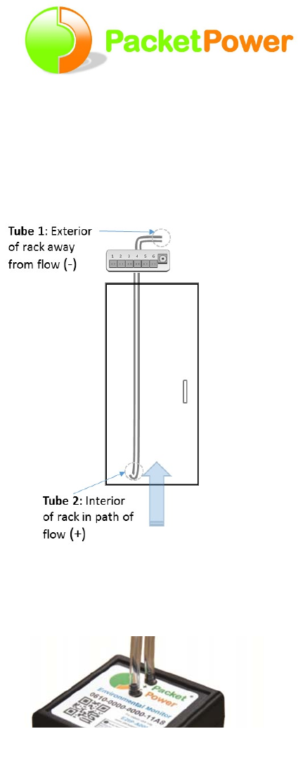
DIFFERENTIALPRESSUREMONITOR:Monitorsequippedwith
thedifferentialsensingoptioncansensechangeinairpressure
betweentwoareas.Tomonitordifferentialpressurethetwo
sensingtubesneedtobeplacedinareaswithdifferentpressures
suchisanoppositessidesofabaffle,raisedfloororserverrack.
MONITORINGAIRFLOW:Byplacingonetubeindirectpathof
theflow(i.e.atthebaseofaservercabinetbytheairintake)and
thesecondtubeintheambientareawithlittleairflow(i.e.the
topexterioroftheservercabinet),theresultingpressure
differentialwillbeindicativeofthedegreeofairflow.Keepin
mindthatthisisnotameasurementofairflowbutrathera
relativeindication.Alowerdifferentialpressurewillindicatea
lowerairflowrateandahigherpressurevalueahigherflow
rate.
Notetheareamonitoringthehigherpressure(orfasterairflow)
shouldusethetubemarkedwiththe(+)positivesymbol.Thearea
withthelowerpressureorslowerflowshouldusethetube
markedwiththe(‐)negativesymbol.Thedifferentialpressureis
expressedinPascals(±500Pain0.2Paor±3%accuracy)
HUMIDITYSENSING
HUMIDITY:Environmentalmonitorsequippedwiththehumiditysensingoptioncansenserelative
humidity.Thehumiditysensorisembeddedinsidethemonitor.Placementofmonitorshouldbeinan
open,non‐enclosedenvironment.Humidityismeasuredfrom0to100%RelativeHumidityat±2%RH
at0.1%resolution.
Monitorwithdifferentialpressure
sensingoption.
ServerRackFlowSensing:Intheabove
applicationthedifferentialpressurewill
increaseastheairflowspeedincreases.
©2014PacketPowerLLCwww.packetpower.comEM31.2 17
E306LCDDisplay
DRYCONTACTSENSING
BoththeE306andE312monitorscanbeusedtosensethestatusofdrycontactcircuits(i.e.openor
closedstatus)usinganyofthetemperatureprobeports.ConsultwithPacketPoweronhowtoconfigure
yourdevicesfordrycontactclosure.ConsultPacketPowerwhenusingthedevicefordrycontacts.
DISPLAYANDCOMMUNICATIONS
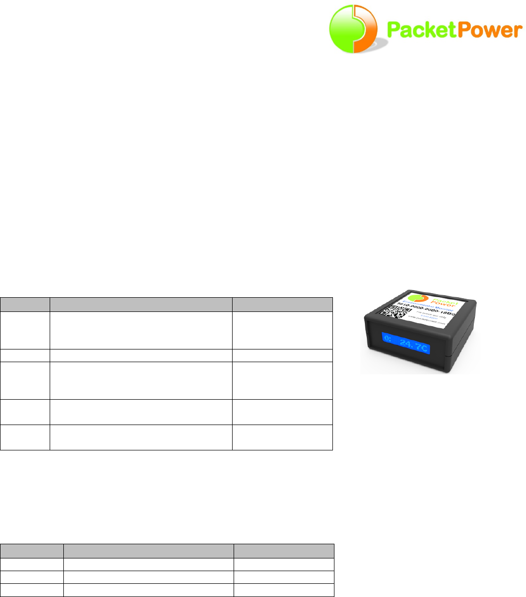
LCDDISPLAY(E306Monitor):TheE306monitorincludesalocalLCDdisplaythatwillindicatethedevice
status,andinputmeasurementsinarotationindicatedinthechartbelow:
DisplayDescriptionDisplay
COM:Communicationsstatus(indicatesifthe
deviceisproperlycommunicationwith
thegateway)
[NONE]/[OK]
0:Internaltemperaturesensor[XX.XC]…[XX.XF]
1‐6:Probe1‐6status;eithertemperature
measurementordrycontactstatuswhen
usedasdrycontactinput
[XX.XC]…[XX.XF]
OR[OPEN]OR
[CLOSED]
RH:Relativehumidity(onlyonmonitors
equippedwithrelativehumidity)
[XX%]
DP:Differentialpressure(onlyonmonitors
equippedwithdifferentialpressure)
[XXXP]
LEDDISPLAYANDCONTROLBUTTON(E312Monitor)
TheE312monitorincludesalocalLEDdisplaythatwillindicatethedevicestatusaswellasbattery
status.
FunctionDescriptionDisplay
GreenLED
RedLED
Button
OPEN(NON‐CONNECTED)ANDCLOSED(SHORTED)PORTS:Whenthereisnoprobeinthepluggedinto
aprobeport,theLCDdisplayandthetemperaturereadingwillread“‐48C”.“‐48C”canbeusedasa
finitenumbertoindicateanunpluggedprobeport.Likewiseareadingof“+75C”willbecausedfroma
deadshortontheprobeorcontactclosure.Thesevaluescanbeusedtogeneratealarmconditionsfor

©2014PacketPowerLLCwww.packetpower.comEM31.2 18
openorclosedconditionswhenusingdrycontactsinplaceof
temperatureprobes.ConsultPacketPowerwhenusingthedevicefordrycontacts.
NETWORK/GATEWAYINTERFACE
GATEWAYVERSIONS:DependingontheGatewayversionselected,theoutputwillbeeither[SNMPor
ModbusTCP/IP]forexporttoathirdpartyapplicationordirectoutputtotheEMXportal(Packet
Power’smonitoringapplication).ConsultwithPacketPowerifyourequireaGatewaytocommunicate
onadifferentprotocol.
RefertotheGatewayQuickStartGuideforthesetupandplacementofGateway
Moduleswww.packetpower.com/support
NODEID:EachmonitoringnodeisequippedwithadeviceIDcodemarkedon
thetopofthemonitor.ThisdeviceIDcodewillalsobetransmitted
electronicallyandcanbeobtainedbytheQRcodeprintedonthedevicelabel.
ThedeviceIDwillidentifythenodesonthevariousmonitoringand
configurationapplications.
ADDINGMONITORINGNODESANDSCALINGTHENETWORK:ThePacketPowerarchitectureallowsup
to300monitoringdevices(powerorenvironmental)perGateway.Gatewayscanbeaddedtoincrease
systemcapacityandaddredundancy.RedundantGatewaysarealwaysrecommendedforcritical
systems.ThesystemcanbescaledbysimplyaddinganadditionalGateway(s)tosupportthousandsof
modulespernetwork.AdditionalGatewayswillautomaticallyoptimizethenetworkconfigurationand
balancethedatatrafficbetweenthem.
CONNECTIVITY:ThemonitorisdesignedtointerfacewiththePacketPowerEthernetGatewaymodule.
Multiplemonitors(upto300)maybeusedwithasingleGateway.RefertotheEthernetGateway(EG3)
devicemanualforinformation.DependingontheinformationrequiredtwoversionsofGatewaysare
availablewithSNMPorModBusTCP/IPoutputforintegrationwiththirdpartymonitoringsystems.All
GatewaysarealsocapableofsimultaneouscommunicationwiththeEMXmonitoringportal.
Device
ID

©2014PacketPowerLLCwww.packetpower.comEM31.2 19
EMXPortalversion:TheEMXEnergymanagerisaplugandplaymonitoringsolutionthatistheeasiest
waytoview,logandmanagedatafromallPacketPowermonitoringdevices.Thesystemofferseasy
accesstoenergyanalysis,real‐timedataandhistoricalreports;userdefinedalertsviaemailorSMSand
detailed,easilycustomizedreports.RefertotheEMXbrochureforaproductoverview.‐
http://www.packetpower.com/Portals/23344/docs/em3.pdf
EMXPortalFeatures:
Cloudbasedoravailableasalocallyinstalledapplication
Instantlypopulates–nocommissioningrequired
Integratespowerandenvironmentaldata
Createcustomdashboards,dynamiccharts,customreports,alertsandmuchmore
EMXMonitoringPortal
s

©2014PacketPowerLLCwww.packetpower.comEM31.2 20
TECHNICALSPECIFICATIONS
MEASUREMENT
Temperature:±1°Cat0.1°Cresolutionwithreadingsin°Cor°F.
RelativeHumidity:From0to100%RHat±2%RHat0.1%resolution
DryContact:ContactPacketPowerforspecificsensingdevices
DifferentialPressure:±500Pa(±2”H20),0.2Paor±3%accuracyfullspan
COMMUNICATIONS
OperatingFrequency:860to920MHzand2.4GHz(frequenciesvarybyregion)
WirelessNetworkProtocol:Frequencyhoppingself‐configuringload‐balancingmesh
DataOutput:SNMPandModbusTCP/IPprotocols
FirmwareUpdates:Wireless
TypicalTransmissionRange:10to30metersindoorsbetweenanytwodevicesinmeshnetwork
Antenna:Fullyenclosed,fixedconfiguration
MonitoringUnittoGatewayRadioRange:Upto300monitoringunitspergatewayandunlimitedGatewaysper
site
Multi‐siteSupport:Yes
Encryption:128‐bit
SystemStatus:LocalLCDdisplayonE306models
OPERATINGENVIRONMENT/MECHANICAL/POWERSUPPLY
OperatingTemperature:MonitoringUnit:0°to+40°C(+32to+104°F)
Temperatureprobes:‐40°to+85°C(‐40to+185°F)
OperatingHumidity:10%to90%non‐condensing
WaterandDustResistance:NEMA1/IP20(indooruse)
ModuleSizeandWeight:(E306)65mm(2.6”)x65mm(2.6”)x28cm(1.1”),90g(3oz)
ModuleSizeandWeight:(E312)80mm(3.1”)x53mm(2.1”)x40cm(1.6”)(3oz;5ozwithbatteries)
Batteries(E312only):2xAA(included)
ExternalACPowerSupply:100‐240VACinputvoltage,50‐60Hz/5VDCoutput;0.5Wpowerconsumption
PowerSupplyPlugTypes:C14,NEMA1‐15,EuroCEE7/16,ANZAS3112,ChinaGB2009,UKBS1363,IndiaBS546

©2014PacketPowerLLCwww.packetpower.comEM31.2 21
SUPPORT
ONLINESUPPORT:http://www.packetpower.com/support/
EMAIL:support@packetpower.com
PacketPower,LLC
2716SummerStNE
Minneapolis,MN55413
www.packetpower.com