Palmer Environmental MD MicroCorr Digital Leak Detector Out-Station User Manual MicroCorr 6 short form manual
Palmer Environmental Ltd MicroCorr Digital Leak Detector Out-Station MicroCorr 6 short form manual
Contents
- 1. User manual pt 1
- 2. User manual pt 2
User manual pt 1

2
MicroCorr Digital Users Guide
Introduction and Features.......................................................................................................... 3
New features.............................................................................................................................. 3
Operational Benefits .................................................................................................................. 4
Principle of Correlation .............................................................................................................. 5
System Overview....................................................................................................................... 6
Standard system configuration .................................................................................................. 6
Optional accessories ................................................................................................................. 6
Fully Digital Correlation ............................................................................................................. 7
Features of the correlator unit ................................................................................................... 8
Features of the Out Stations...................................................................................................... 9
MicroCorr® DIGITAL correlator unit operational features ........................................................ 11
Key functions ........................................................................................................................... 11
Using the MicroCorr Digital Correlator................................................................................... 12
BATTERY WARNING.............................................................................................................. 12
Step 1: Charging and installing batteries................................................................................ 12
Step 2: Set up and deployment of Out Stations ..................................................................... 14
Step 3: Switching on the Correlator........................................................................................ 15
Correlating ............................................................................................................................... 16
Main Menu ............................................................................................................................... 17
Correlate ..................................................................................................................... 17
File .............................................................................................................................. 17
Regression Analysis ................................................................................................... 19
Set-up ......................................................................................................................... 22
Test and Service......................................................................................................... 24
Other System Options ................................................................................................ 26
Correlation Screen................................................................................................................... 27
Pipe data..................................................................................................................... 28
Zoom........................................................................................................................... 32
Peak Suppression Screen .......................................................................................... 33
View Settings .............................................................................................................. 34
Calculate Velocity ....................................................................................................... 35
Filters ....................................................................................................................................... 37
Program upgrade (Software and Firmware)............................................................................ 40
Technical Specification............................................................................................................ 43
Warranty .................................................................................................................................. 45
Patents..................................................................................................................................... 45
3
MicroCorr Digital Users Guide
Introduction and Features
MicroCorr® DIGITAL is the latest model of the world’s leading correlator brand (over 4,000
MicroCorr® units in use worldwide) but is the first fully digital system. This enables it to
achieve performance levels well in excess of previous analogue-based systems, with
important benefits to the user.
• Totally digital system
• Superior leak detection performance on all pipe materials and sizes
• Quick and easy to use, especially for less experienced operators
• Automatic parametric filtering (APF)
• Ergonomically designed – lightweight, compact system
• 1/4 VGA colour display
• Software upgrades via Internet web site
• Optional third Out Station for velocity measurement and rapid survey
• Select dedicated or PC-based models
New features
• Transceiver communication enables all system functions to be controlled centrally,
enabling quicker deployment
• Expert system leak detection algorithms eliminate transient, non-leak effects
• Tricorrelation (optional third Out Station/sensor) automatically calculates site-
specific velocity
• Data replay function allows immediate post-processing or off-line correlation
• Software upgrades downloaded directly from www.palmer.co.uk
• Results transferable into Windows PC for post-processing or export
Best in the field
Leak detection staff require a high performance correlator in order to maximise their
productivity (number of leaks found per hour) and minimise the incidence of “dry” holes, when
excavation reveals no leak to be present. However, because it is used constantly in the field,
the correlator must also be robustly designed.
The Control Unit and Out Station are injection-moulded housings, providing maximum
strength and durability. They are designed to IP65 protection and to survive a 1 metre drop.
The Control Unit incorporates an external antenna and a magmount antenna (optional extra)
may be connected for longer correlation distances if the Control Unit is vehicle-based.
External antennae are used with the Out Stations.
All connectors are military specification and cables are fitted with strain relief to protect
against fatigue damage. The complete system, comprising control unit with two Out Stations
and sensors, is easily carried by one person. The Out Stations have been designed to be
visible over typical correlation distances and allow back-to-back portability.
4
Operational Benefits
• Pinpoints a higher percentage of leaks...
• ...and a significantly higher percentage of “difficult” leaks (plastic pipes, trunk mains, low
pressure situations)
• Fewer “dry” holes reduces excavation costs
• Improved productivity – more leaks found per hour
• Easier to use – less training required
• Improved reliability with less downtime
• Lightweight and robust
• Easily integrates into Company-specific reporting
• New software versions available from www.palmer.co.uk
• Ground microphone “foot” option to improve versatility
• Permalog “Patroller link” option to improve versatility
• Designed for easy portability
Fully automatic
• Immediate correlation – switch on and go (enter pipe details later)
• Automatic parametric filtering (APF)
• Velocity measurement using (optional) third Out Station/sensor
Easier to Use
• Colour graphical user interface
• Intuitive display and operation
• Quick correlation
• Batteries field-changeable
Reliability to inspire confidence
• All functions self-calibrated automatically on power-up
• In-built power management
• Increased battery life – batteries rechargeable and field replaceable
5
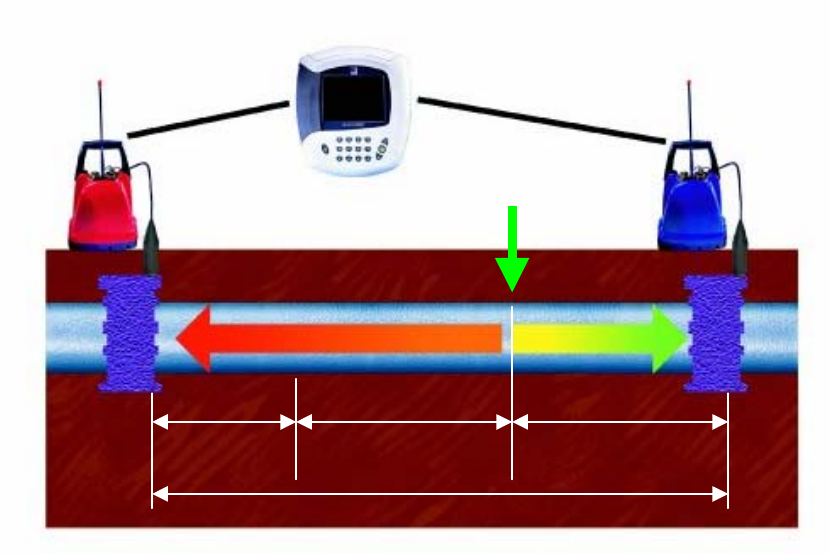
Principle of Correlation
In the "classic" correlation process, two sensors are deployed on pipe fittings ("dry"
connection) or connected to hydrants ("wet" connection). The sensors are positioned either
side of the suspected leak position. Noise is created by the leak as it escapes from the pipe
under pressure. This noise is conducted in both directions away from the leak through the
pipe wall (as minute vibrations) and through the water column (as a pressure wave). The leak
noise travels at a constant velocity (V), which depends on the material and diameter of the
pipe, and arrives first at the sensor nearer the leak. The arrival time at each sensor is
registered. The difference (Td) between the two arrival times, combined with knowledge of the
pipe type and length, enables the leak position to be calculated by the correlator. Depending
on the environmental conditions, accuracy of leak pinpointing can be to within centimetres.
Principle of correlation: L = ½ (D-(VxTd))
Leak position
V x Td L L
D
6
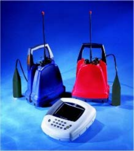
System Overview
Standard system configuration
The standard MicroCorr Digital system comprises
the following equipment:-
1. Control Unit
2. External Antenna for C.U.
3. Carry strap for C.U.
4. Red Out Station
5. Blue Out Station
6. 2 x External Antennae for O/S
7. 2 x Digital Sensors with cables
8. Headphones (for use with C.U. or O/S)
9. MicroCorr Digital PC communications
cable
10. Mains power supply/charger for 2 Out
Stations
11. Mains power supply/charger for Control
Unit
12. 12V DC power/charge lead for C.U. or
O/S
13. Operating manual
Optional accessories
1. PC software (for upgrades, diagnostics, PC interface)
2. Spare battery pack with charge lead
3. Vehicle magmount antenna with cable
4. Digital hydrophones with cables (set of 2)
5. Leak noise CD
6. Digital microphone foot
7. Tripod or ground plate for accelerometer (magnetically attached)
8. Printer cable to standard Epson/HP printer
9. Rechargeable colour printer with batteries
10. “Tricorrelation” 3rd (yellow) Out Station and digital sensor, with antenna and
charge lead
11. Measuring Wheel
12. Soft carry bags for control unit and Out Station(s)
13. Hard transit case for all system components.
14. Permalog Patroller radio unit

7
Fully Digital Correlation
Digital sensor
• New sensor with improved sensitivity to low frequency noise (for plastic
and large diameter pipes and low pressure situations) - down to 1.0Hz
• Wider dynamic range than any previous sensor - can distinguish leak
noises much quieter than previous sensors
• True 16 bit Σ∆ ADC with 10kHz sampling
• Immediate digitisation of received signal
• Low noise electronics with digital protocol eliminates interference
• Longer sensor cables possible
Digital radio Out Station
• Two-way communication with control unit using transceiver technology
• Virtually no data loss, interference or distortion of the transmitted signal
• Single radio frequency for all Out Stations
• Improved dynamic range over analogue radios
• High speed data transmission using transform
coding techniques
• No directional restrictions
New digital sensor with enhanced low frequency
sensitivity
8
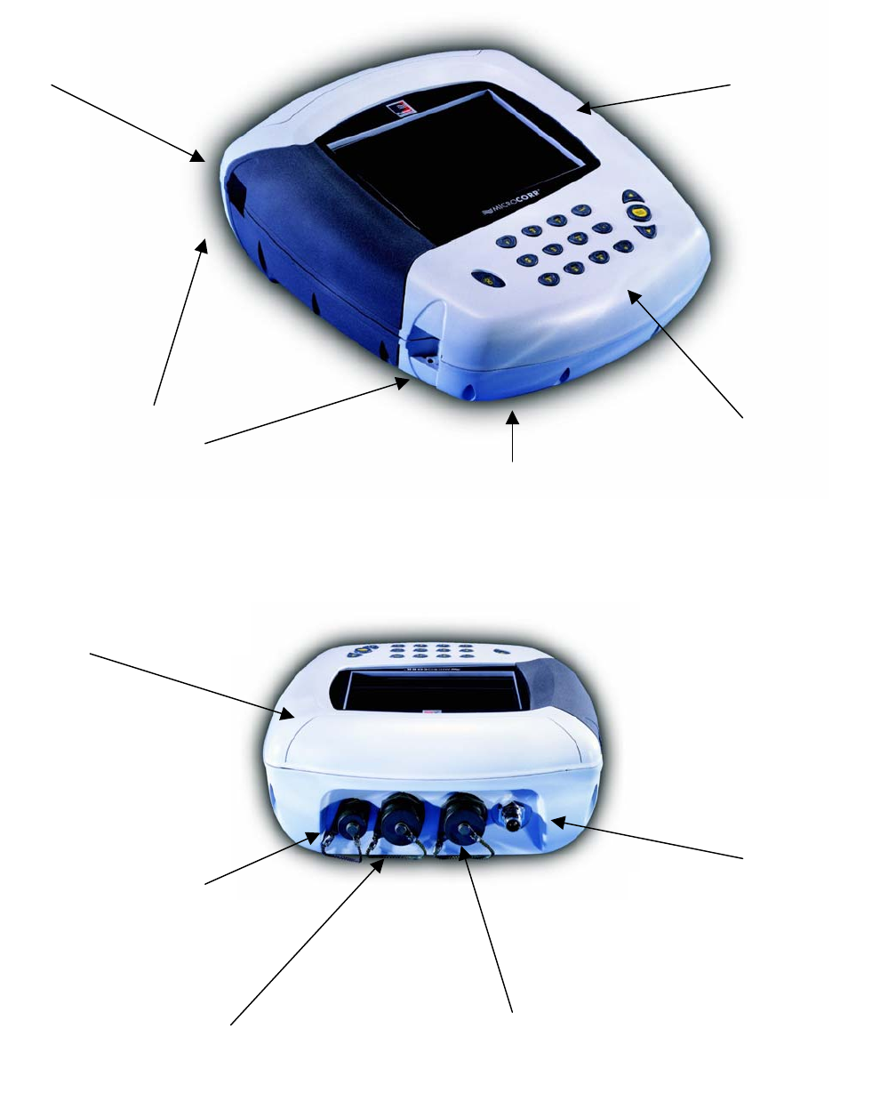
Features of the correlator unit
Large backlit colour display
with protective screen
Tactile rubber keypad
Rubber hand grip
Carry-strap attachment
External antenna / magmount
connection
Headphone / charger
connector
Injection moulded housing
Sensor
connector
Communications
connector
Battery compartment
(accessed from underside)
9
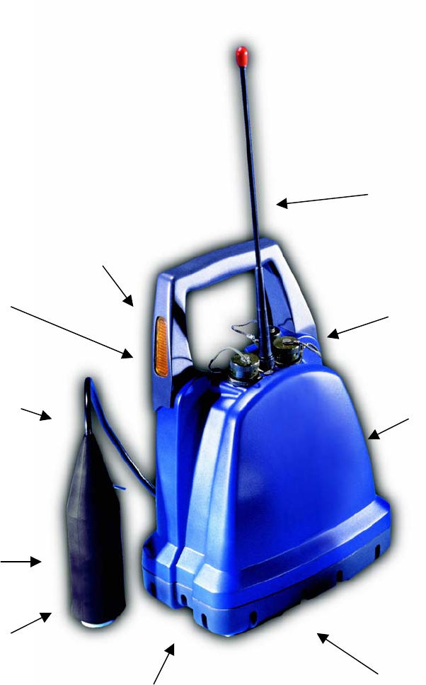
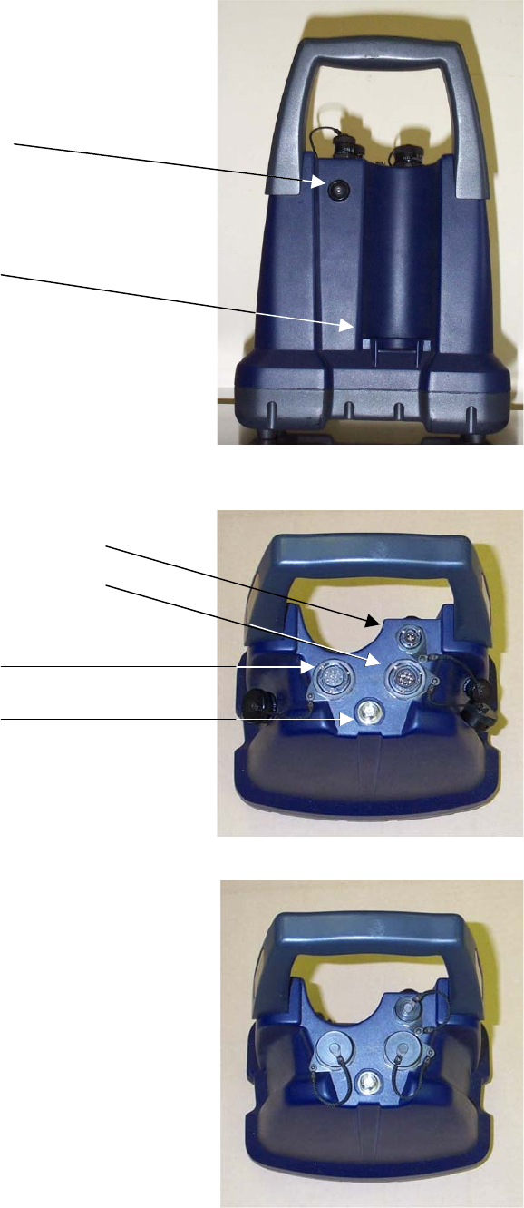
Features of the Out Stations
The Out Station consists of a transmitter unit (red, blue – or optionally yellow) and a digital
sensor unit complete with cable to connect to the transmitter. Its design incorporates sensor
stowage and cable wrap.
Sensor
stowage
at rear
Flashing
hazard
lights
Cable with
strain relief
Digital
sensor
High
strength
magnet
Cable wrap
Battery compartment
(accessed from underside)
Injection moulded
housing
Military
specification
connectors
Detachable
antenna
10
Rear of transmitter
On/Off switch with integral
flashing LED
Sensor stowage
Top view of transmitter – connector covers removed
Headphones / charger connector
Communications connector
Sensor connector
Antenna connector
Top view of transmitter – connector covers fitted
11
MicroCorr® DIGITAL correlator unit operational features
The unit performs accurate leak noise correlations for leak positioning and velocity
measurement. It has listening and surveying facilities and its stored information can be
downloaded to a computer or printer.
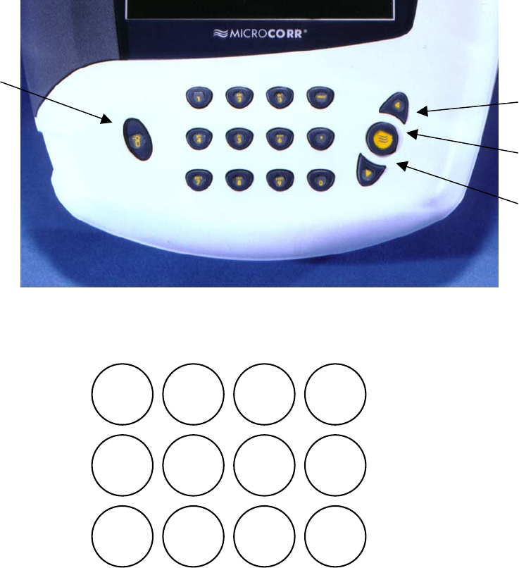
Key functions
Keypad
functions
MicroCorr Digital has an alpha-numeric keypad, similar to that of a mobile phone including a
full stop, cancel, enter and up/down arrows. Navigation through the menus uses
combinations of these keys.
• UP/DOWN arrows will select items from within a list
• Numeric to select menu item
• Enter to accept input
• Cancel to move back a menu level.
1abc
2
def
3
CANCEL
jkl
5
ghi
4mno
6
pqrs
7
tuv
80
wxyz
9
.
On / Off
button
Up arrow
Down arrow
Enter button
12
Using the MicroCorr Digital Correlator
BATTERY WARNING
All three batteries supplied are rechargeable lithium ion. Do not short circuit these
batteries. Any misuse of these batteries may result in explosion or fire. They must not
be used in any other application or used with any other equipment. Only
batteries/battery-packs supplied by Palmer Environmental must be used.
The Palmer sealed battery packs contain circuitry to prevent overcharging and
overdischarging.
Step 1: Charging and installing batteries
The battery packs for the correlator and the Out Stations are supplied as separate items and
will need to be fully charged although they are supplied quarter charged.
Two different battery chargers are supplied: one for the correlator and one for both Out
Stations to be charged simultaneously. All three batteries are identical and are
interchangeable. Charging for all batteries takes up to 4 hours from flat.
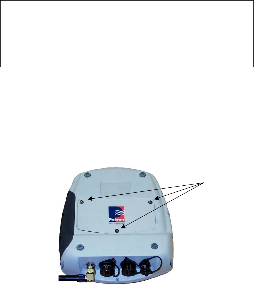
Charging the Correlator
1. To charge the correlator battery, the battery must first be fitted inside the correlator.
2. To insert the battery pack into the correlator unscrew the three screws underneath
the unit, remove the cover and packing foam and connect the battery pack, place in the
battery compartment, refit the packing foam, and then replace the cover with the three
screws.
3. Connect the charge lead from the correlator charger to the headphone / battery
charge connector on the back of the correlator. Plug the charger unit into the mains supply
and switch on. The correlator will turn itself on and display the battery indicator as charging on
the correlation screen.
Unscrew these
3 quick-release
screws to
remove battery
compartment
panel.
13
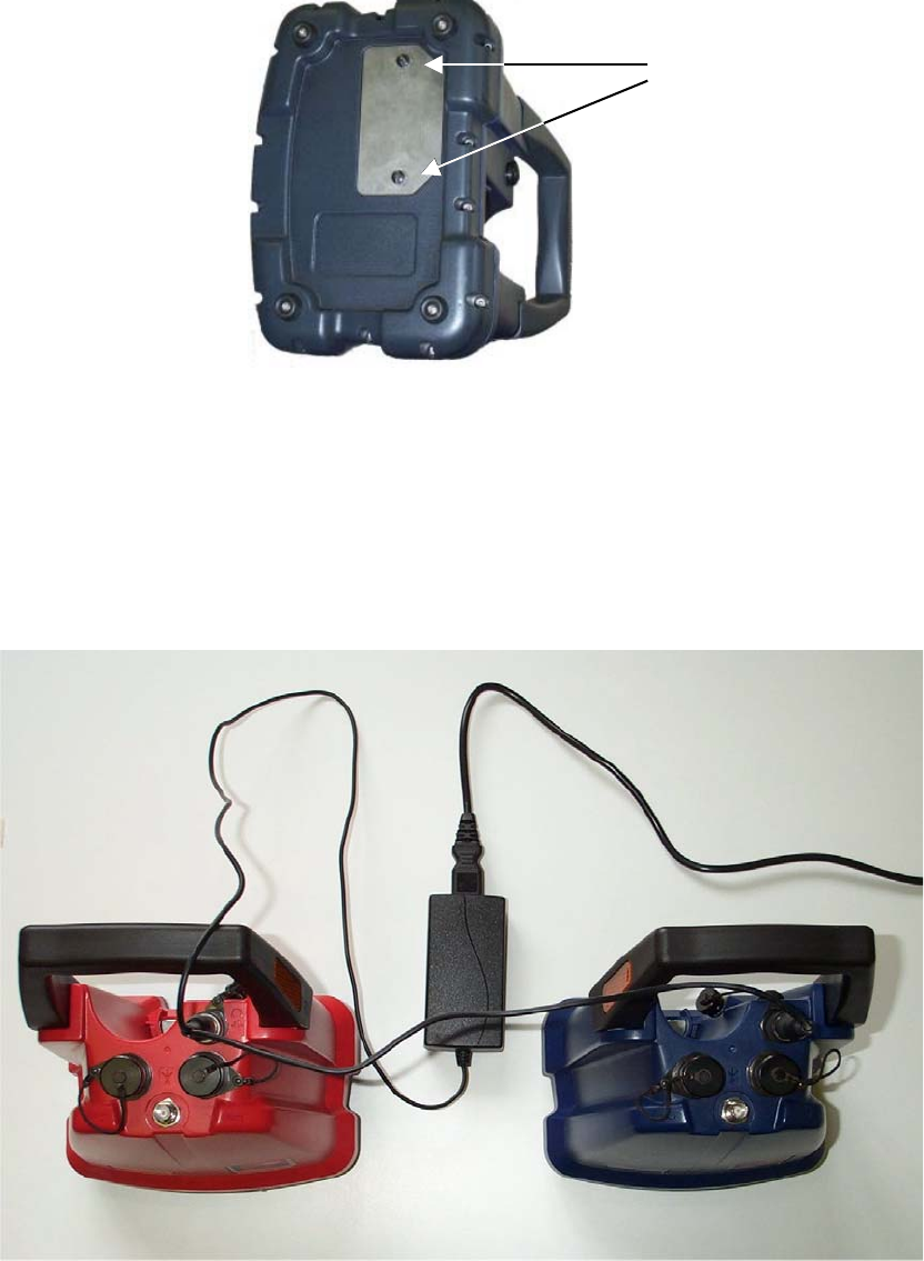
4. To charge the Out Station batteries they must first be installed. To do this remove the
screws from the battery compartment on the bottom of each Out Station, connect the battery
lead to the connector and insert the battery. Refit the screws and attach the battery charge
lead to the headphone / charge connector on the top of the transmitter. The Out Stations will
turn themselves on to charge.
Remember to turn control unit and Out Stations off after disconnecting charger cables.
Although the batteries are rechargeable, they may eventually need to be replaced. Only
batteries configured to the correct specification and type must be used. These are available
from Palmer Environmental.
TWO OUT STATIONS CONNECTED VIA CHARGER TO MAINS
Unscrew these
2 quick-release
screws to
remove battery
compartment
panel.
14
Step 2: Set up and deployment of Out Stations
1. Once the batteries have been charged and installed in the correlator and the Out
Stations, connect the antennae, connect a sensor cable and sensor to each Out
Station. Switch on each transmitter by pressing the On / Off button on the back.
2. Transmitter switch functions
To switch the transmitter on, press the switch on the rear of the transmitter once
momentarily. The beacons will flash once.
To switch the flashing beacons on, press the switch momentarily again.
To switch the flashing beacons off, press the switch momentarily once more.
To switch the transmitter off, press the switch and hold it in for at least 2 seconds.
The beacons will flash three times before the Out Station turns off.
3. Green LED functions
The switch incorporates a green LED, which provides the following functions:-
When lit constantly the transmitter is charging.
When flashing rapidly, the transmitter battery is almost fully charged.
When flashing steadily, the transmitter is switched on and performing normally.
When there is a long flash this indicates the battery is discharged and requires
charging.
Deploy each sensor on a water pipe fitting either side of the suspected leak position. The
sensor has a strong magnet that will enable it to remain in position on steel / iron fittings.
Always try to make a debris free contact between sensor and fitting for the best possible
results.
To check sensors are working correctly, connect sensors as normal to Out Station. Connect
headphones to the Out Station and listen while running your finger over sensor magnet. A
clear crisp noise should be heard.
15
Step 3: Switching on the Correlator
Switch the correlator on by pressing the On/Off switch momentarily. A number of system
tests are carried out on power up to ensure the correlator is fully functional. After a few
seconds the main correlation screen will appear on the display as shown below. Note, this is
the default screen on start-up to enable the operator to start correlating immediately. The
Main Menu screen is accessed by pressing Cancel.
To switch the correlator off, press the On/Off button and select 2, to switch off
To turn off the display only, press the On/Off button and select 1, to put into standby. (If
the correlator is not then used for 2 hours it will switch off). To reactivate the screen, press the
On/Off button again.
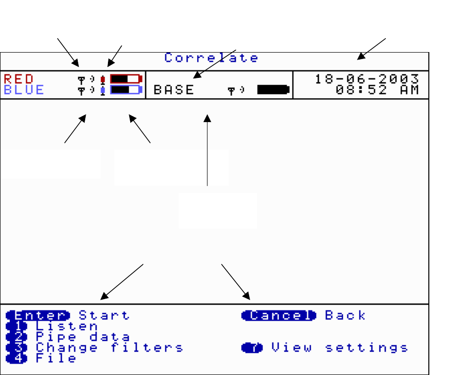
The top menu bar on the correlate screen shows information for each sensor by displaying in
the relevant colour (except Yellow appears black)
Indicates radio signal
is transmitting
Indicates radio
p
ower settin
g
Indicates sensor
connected to Out
Station
Indicates battery
charge level
Date and time
In this situation the Red and
Blue sensors are being used,
they have communication
with the Base unit ok, using
low power
Space where Yellow
Sensor information
would be displayed if
attached
Correlating function options
Control unit
information
16
Correlating
The screen shown on page 15 is the first screen that appears on the control unit when it is
switched on. Once the ENTER key is pressed the system will begin to correlate. Correlation
can be stopped by pressing the ENTER key again.
This can be used for quick surveys without having to input any pipe data.
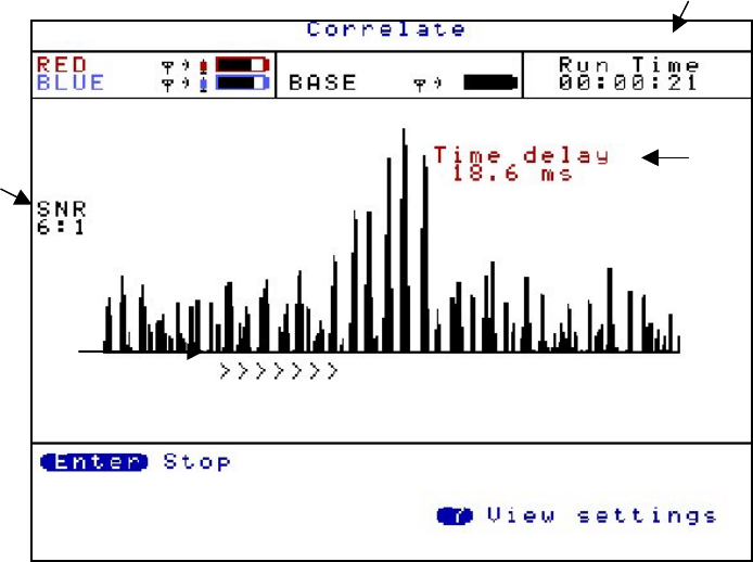
If the Enter key is pressed the control unit will start to correlate as shown below.
Press ENTER to stop correlation, to return to correlator function options
There is an option to select either the Correlate screen or the Main Menu screen as the first
screen to appear after turning on. This can be selected by using the Set-up screen (option 4)
from the Main Menu.
Date and time changes to
the run time of the
correlation
Time delay
Signal to
Noise Ratio
Scrolling arrows
shows correlation
is in progress
17
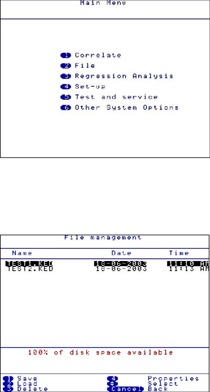
Main Menu
Correlate
See previous page for quick correlation instructions or Correlation Screen section for more in
depth instructions.
File
Enables the user to load previously saved files or save a current correlation. The control unit
can store approximately 30 files.
18
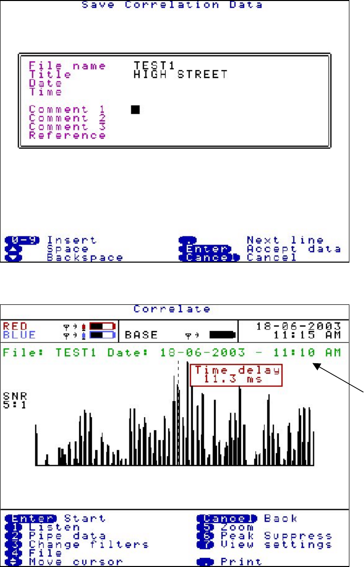
Press 1(Save) The following screen is displayed. The current correlation information details
can be typed and saved.
Press 2(Load) The saved correlation will be displayed. Arrow over the required saved file and
press 2.
From a loaded file the control unit can undertake post correlation. Correlating functions such
as pipe data, filters and peak suppression can be changed on the loaded data without having
to return to site to re-correlate. Using new information may correlate a different result.
Press 3(Delete) Deletes a previously saved file. Use the arrow keys to highlight the file for
deletion and press 3.
Press 4(Properties) Displays file information and comments, when the file was saved. Use
the arrow keys to highlight the file to view and press 4.
Loaded file
name is
displayed
in green
19
Regression Analysis
Regression Analysis provides an additional way of pinpointing leak positions by using a set of
correlation results, rather than an individual correlation result. This also provides a way of
measuring an accurate velocity.
The time delay / distance relationship of the correlation is linear, as the distance between a
sensor and the leak noise increases, the time taken for the sound to reach the sensor
increases proportionally with the distance. For example, if you move the sensor twice as far
away, the sound will take twice as long to reach it. It is this linear relationship that makes it
possible to predict values for varying time delays / distances when using a set of correlation
results.
Before the regression analysis feature can be used, correlation’s must have been saved on
the control unit. For an accurate result it is recommended to save three correlation’s, but
obeying the following two rules :-
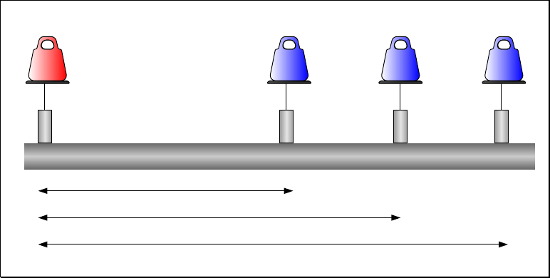
- One of the sensors must remain static during the collection of data. Which of the sensors
does not matter.
- The pipe material and diameter must be constant for each of the correlation results. This
is validated by the control unit.
Red Blue Position
1
Blue Position
2
Blue Position
3
Correlation Result 1
Correlation Result 2
Correlation Result 3
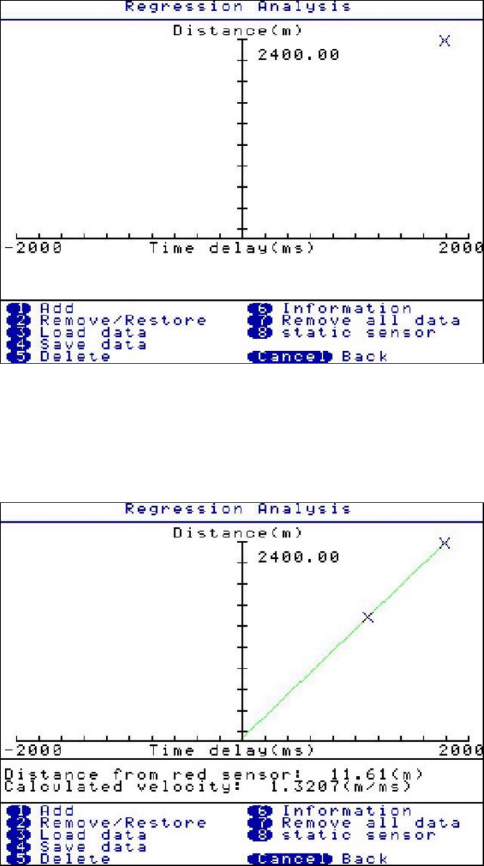
Press 3 (Regression Analysis) After correlation results have been saved. Press 1 to Add a
result, the file screen will appear, select the first correlation result saved.
The control unit will then ask for the “Static Out Station” colour. The control unit will store the
material and diameter of the first correlation result and compare with the next results to be
added, this ensures these details remain constant.
A regression analysis graph will appear showing time delay and distance. A cross will appear
on the graph plotting the first correlation result.
20
Then press 1 to add the second correlation result. A second cross will appear and a line will
pass through both. A result will be given on the leak position and velocity, but we recommend
the user add a third result for a more confident result.
Then press 1 to add the third correlation result. A third cross will appear and a best fit line will
pass through or near the three crosses. The result of the leak position and velocity will be
displayed under the graph.