Palmer Environmental MD MicroCorr Digital Leak Detector Out-Station User Manual MicroCorr 6 short form manual
Palmer Environmental Ltd MicroCorr Digital Leak Detector Out-Station MicroCorr 6 short form manual
Contents
- 1. User manual pt 1
- 2. User manual pt 2
User manual pt 2
21
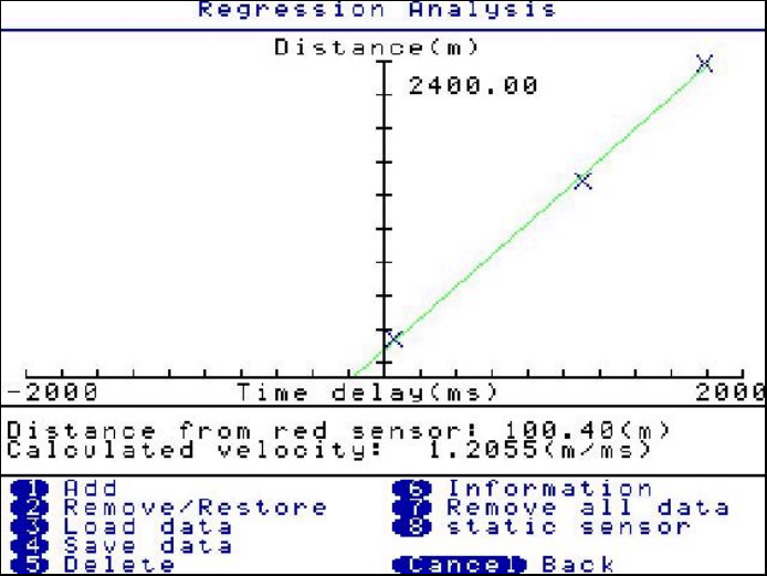
Press 2 (Remove / Restore) Allows you to select a suspicious correlation for removal. After
pressing 2, use the arrow keys to select the cross on the regression graph for removal (a box
appears around the selected cross) then press ENTER.
Press 3 (Load data) Retrieves previously stored regression analysis graph results.
Press 4 (Save data) Saves the current regression analysis graph results.
Press 5 (Delete) Enables the deletion of saved regression analysis files.
Press 6 (Information) Displays correlation information. After pressing 6, use the arrow keys
to select the cross on the regression graph for information to be displayed (a box appears
around the selected cross) then press ENTER
Press 7 (Remove all data) Removes all data currently being used on the regression graph,
you will be prompted to verify your selection.
Press 8 (Static sensor) Allows you to change the colour of the static sensor.
22
Set-up
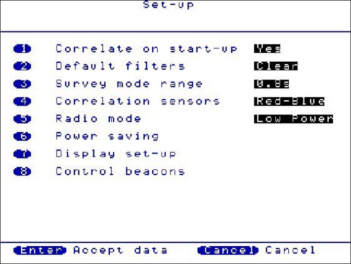
Press 1(Correlate on start-up) Toggles between YES and NO. If set to YES, the control unit
will go straight to the correlate screen after turning on. If set to NO, the control unit will go
straight to the Main Menu after turning on.
Press 2(Default filters) Toggles between CLEAR and RETAIN. If set to CLEAR, in survey
mode, the filters will clear each time a new correlation is processed. If set to RETAIN, in
survey mode, the filters will retain a set filter setting (set by the user) for every correlation
processed.
Press 3(Survey mode range) Toggles between 0.8, 2.4 and 4.0 seconds. Each of these
values provides the time delay range over which the correlator will correlate, where the times
in seconds shows twice the range. For example, over longer distances the 4.0 second range
should be used to give +2 seconds to –2 seconds. If entering pipe data, the survey mode
range automatically defaults to the appropriate setting.
Press 4(Correlation sensors) Toggles between the pairs of sensors to be used. Red-Blue,
Red-Yellow, Blue-Yellow, Base-Red, Base-Blue and Base-Yellow.
Press 5(Radio Mode) Toggles between HIGH power and LOW power. LOW power can be
used over shorter distances and HIGH power over longer distances or areas where a signal
can be interrupted by the environment. The correlator will always default to LOW power when
turning on.
23
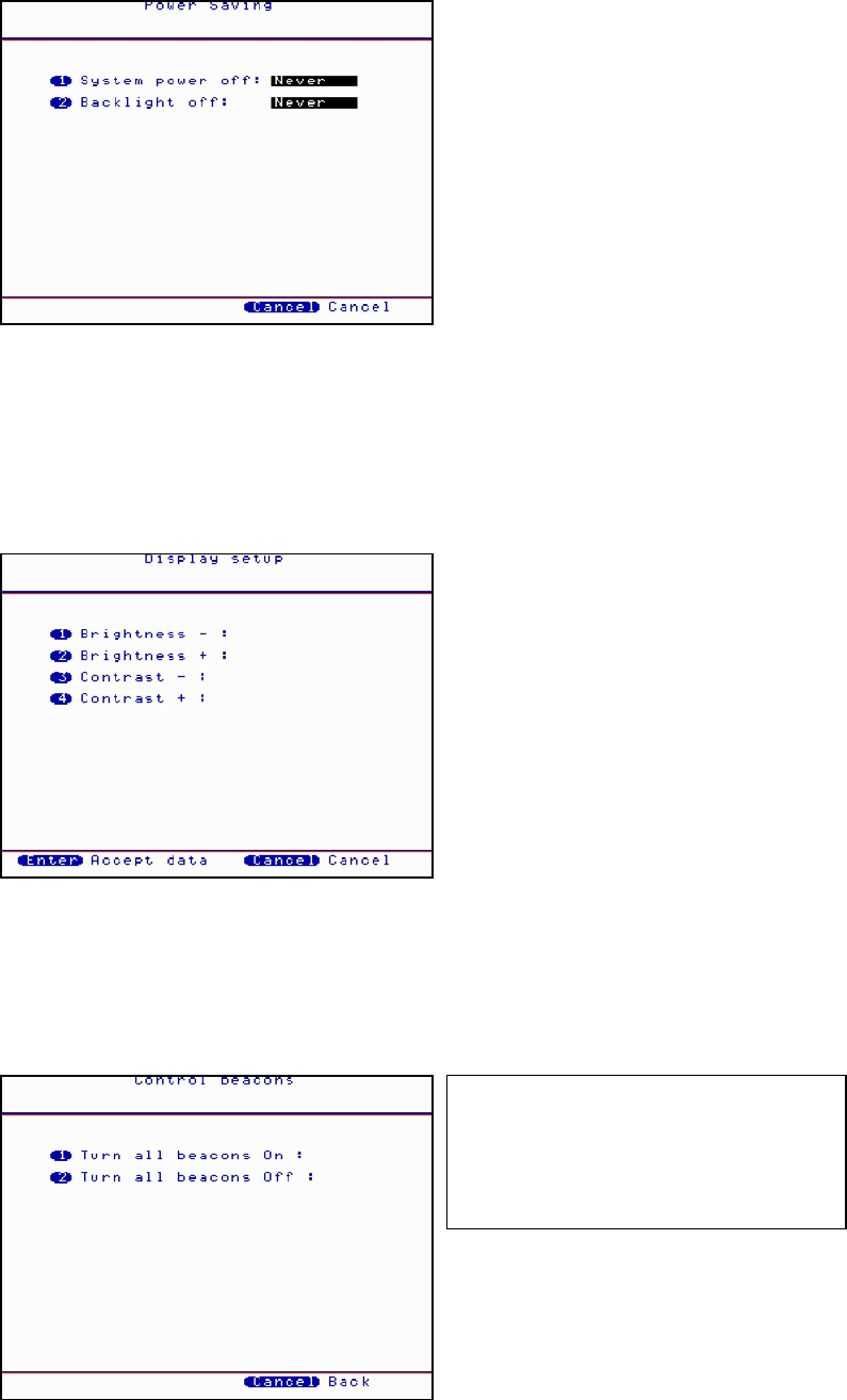
Press 6(Power Saving)
Press 1 to toggle the System power off between NEVER and 5, 10, 15, 20, 25, 30, 35, 40, 45,
50, 55 and 60 minutes duration.
Press 2 to toggle the Backlight off between NEVER and 5, 10, 15, 20, 25, 30, 35, 40, 45, 50,
55 and 60 minutes duration.
Press 7(Display set-up)
Press 1 to incrementally decrease the screen brightness.
Press 2 to incrementally increase the screen brightness.
Press 3 to incrementally decrease the screen contrast.
Press 4 to incrementally increase the screen contrast.
Press 8(Control beacons)
Press 1 to switch On the flashing beacons on the transmitters.
Press 2 to switch Off the flashing beacons on the transmitters.
Note. The beacons should be
checked when switched on from the
control unit as they will only switch on
if they are within range to pick up the
signal.
24
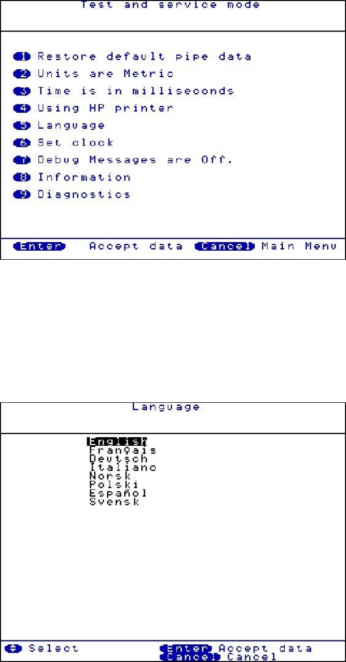
Test and Service
Press 1(Restore default pipe data) Wait a few seconds and the default pipe data will be
restored to the control unit.
Press 2(Units are Metric) Toggle between METRIC and IMPERIAL measurement units.
Press 3(Time is in milliseconds) Toggles between MILLISECONDS and SECONDS
Press 4(Using HP printer) Toggle between HP and EPSON printer.
Press 5(Language) Select the required language by using the arrow buttons.
25
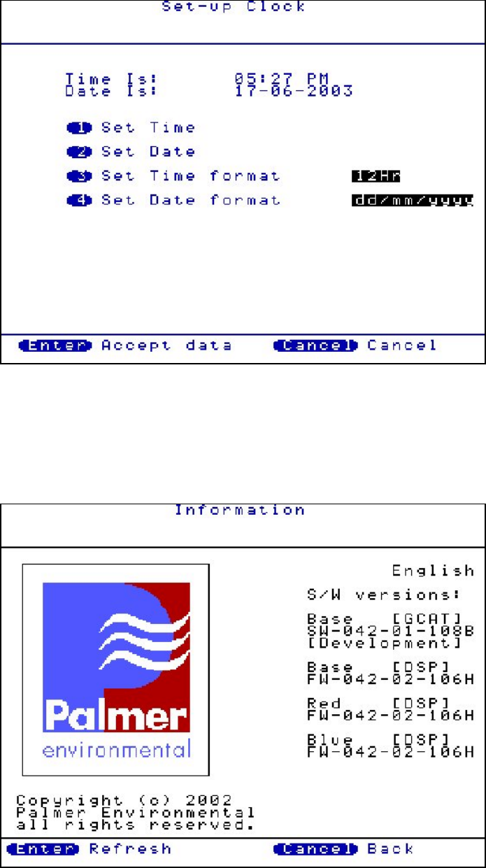
Press 6(Set clock) Set the clock according to the user preferred format.
Press 7(Debug Messages are Off) Toggles between ON and OFF. This should normally be
set to OFF and is normally only used during fault diagnosis.
Press 8(Information) Connect sensors to Out Stations and turn on before pressing 8. This
displays the current firmware and software version currently installed on the MC Digital.
26
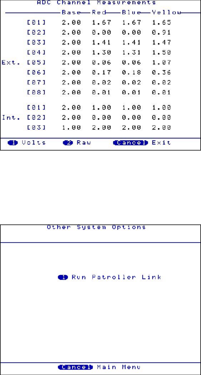
Press 9(Diagnostics) Displays a series of numbers. This is only used during fault diagnosis
Other System Options
The MC Digital is designed for versatility. Pressing 1 will activate the Permalog Patroller Link,
changing the MC Digital into a Permalog Patroller. (This is only possible if the Patroller Link
radio has been purchased, not fitted as standard)
27
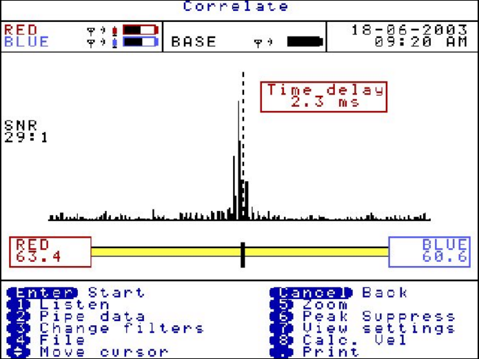
Correlation Screen
A dashed cursor line shows the position of the largest peak (best result). The dashed cursor
line can be moved once the correlation has been stopped, by using the arrow keys. Moving
the dashed cursor line alters the correlation distance.
This screen shows the result of a correlation where the position of the leak is. In this example
63.4 metres from the Red Out Station and 60.6 metres from the Blue Out Station.
The time delay is calculated at 2.3 milliseconds.
The correlation shown has a SNR of 29:1. Signal to Noise Ratio (SNR) means the largest
correlation peak is 29x larger than any other displayed peak shown on the correlation graph.
Hence the larger the SNR the more pronounced the peak will be.
Press 1(Listen) Attach the headphones to the control unit before pressing 1. Use the arrow
keys to select the sensor required to listen to; BASE, RED, BLUE or YELLOW. The sound will
transmit in blocks of approx 20 seconds. To stop listening press ENTER, but note the sound
will continue until the 20 seconds elapses.
28
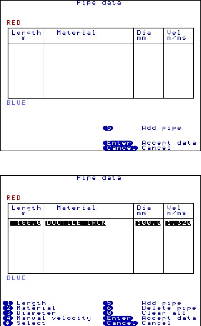
Pipe data
Press 2(Pipe data)
To accurately locate a leak position the user must enter the correct information with respect to
the physical properties of the pipe. Each section must be entered to be accepted by the
system.
Press 5 to Add new pipe data.
A default setting appears.
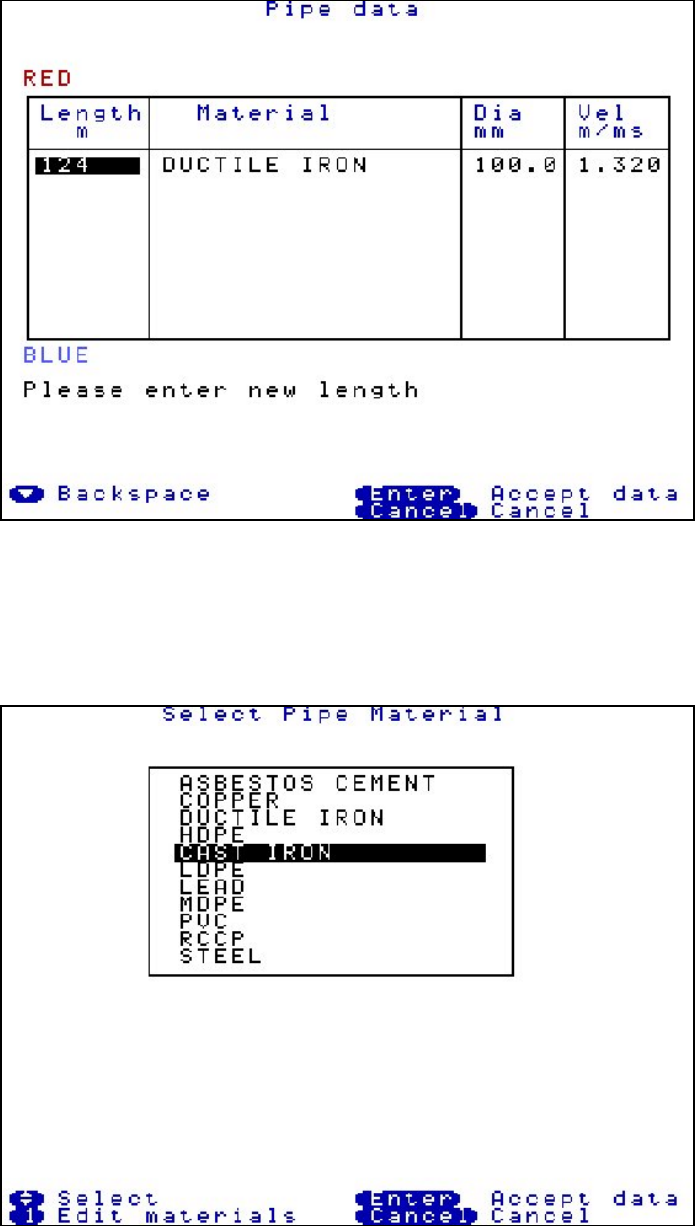
29
Press 1 to enter Length, the distance between the sensors. In this example 124m.
Press 2 to enter material type, use the arrow keys to select the required pipe material and
press ENTER. In this example cast iron is selected.
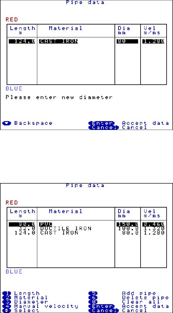
30
Press 3 to enter the diameter of the pipe. In this example 80mm. The velocity column will then
automatically be updated. In this example 1.280 m/ms.
To add another pipe length for mixed material situations, press 5 to add another pipe. If
working on mixed materials, work from the sensor colour displayed at the bottom of the pipe
data screen, back to the sensor colour at the top of the screen. Up to 6 mixed materials can
be used in one correlation. In this example, from the blue sensor the cast iron pipe was
entered first, the ductile iron pipe was second and the PVC pipe was third.
31
To delete a pipe, use the arrow keys to highlight the relevant pipe to remove and press 6.
To delete all pipe data press 0.
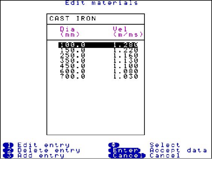
To use a manual velocity the user has calculated, press 4 and type in the new velocity value,
this will automatically update the default value for the current correlation only.
To enter and store extra user defined velocity’s and diameters, press 2 Materials, then press
1 Edit materials, then press 1 Edit table, then press 3 Add entry. To restore to factory set
values see Test and Service menu.
32
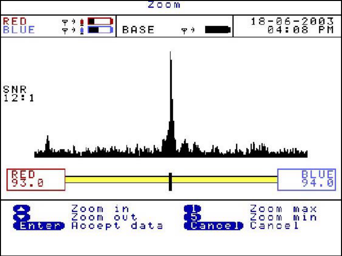
Zoom
Press 5 (Zoom) To see a more enhanced view of the leak centred around the dashed cursor
line. Moving the dashed cursor line along the graph to the required point then press 5.
Use the arrow keys to zoom in or out stage by stage.
For a quicker zoom press 1 to zoom to maximum view or press 5 to zoom to a minimum view.
33
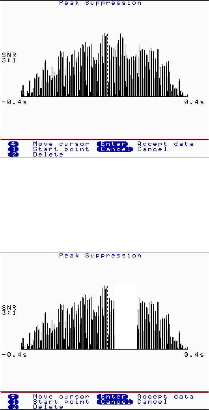
Peak Suppression Screen
Press 6(Peak Suppression) To suppress a section of the time delay range from the current
correlation. This may be used to remove known leaks or demand usage that may be hiding
unknown leaks.
Move the dashed cursor line to the start point of the data to be removed and press 1 to select
a start point. A small arrow will appear below the correlation graph. Move the dashed cursor
line along the data to select the stop point. Press 1 again and the section of the data to be
suppressed will disappear from the correlation graph as shown below.
Press Enter to accept the data and a new correlation can be carried out without the
suppressed data. To replace the removed data press 2 delete.
34
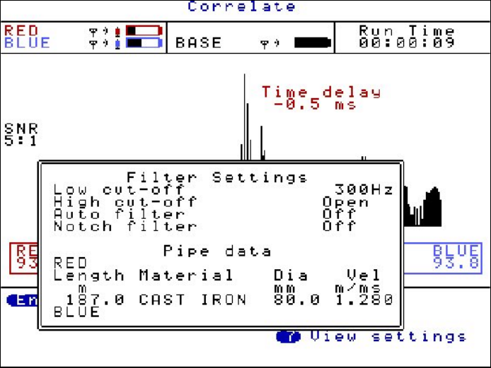
View Settings
Press 7 (View Settings) During correlation or after stopping a correlation press 7 to view all
pipe data and filter settings currently in use. A pop up box appears to display the information.
Press Cancel to remove the display.
35
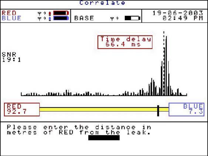
Calculate Velocity
Press 8(Calc Vel) After stopping correlating the option to calculate velocity appears. A
velocity check gives a more accurate velocity of the pipe to be correlated instead of using the
default velocity value.
To calculate velocity a leak must be present, either real or induced. The leak can either be
between the sensors called an “In Bracket” check or outside of the sensors called an “Out of
Bracket” check. Unlike correlation, where the more central the leak is positioned between the
sensors, the more accurate the result. A velocity check requires the leak to be positioned
closer to one of the sensors to create a larger time delay.
The procedure for a velocity check is to position your sensors as described above. Induce
your leak or use the real leak. Correlate as normal entering the correct pipe data. After a good
correlation peak, stop correlating and press 8(Calc vel). The screen below will be displayed.
Enter the position of the leak from the RED Out Station.
If the leak is “In Bracket” between the sensors, then enter the distance from the leak to the
RED sensor. (In this example 92.7m)
If the leak is “Out of Bracket” to the left of the RED sensor, then enter the distance 0
If the leak is “Out of Bracket” to the right of the second sensor, then enter the distance
between the RED sensor and second sensor.
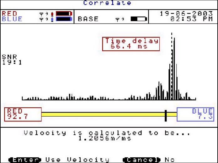
36
A new velocity will be displayed under the correlation graph
The control unit then gives you the option to either use the calculated velocity by pressing
ENTER or CANCEL to ignore it.
By accepting the calculated velocity value, the default velocity value under Pipe Data will be
replaced with the new calculated velocity value. A new correlation position may now be
displayed using the more accurate velocity value.
37
Filters
If correlating with pipe data entered, the default filter settings will be used depending on the
properties of the pipe. Some times this may not be accurate enough to filter out unwanted
frequencies, so the user may wish to alter the filer settings to remove certain frequencies that
are influencing the current correlation.
Press 3 (Change Filters) Displays a pox up box with four options :-
Quick set-metallic
Quick set-non metallic
Clear all
Manual settings
By using the arrow keys highlight the required option and press ENTER
Quick set-metallic removes all frequencies from 0Hz to 405Hz. So the sensors will only
listen to frequencies of 406Hz and above.
Quick set-non metallic removes all frequencies from 696Hz and above. So the sensors will
only listen to frequencies of 695Hz and below.
Clear all removes any filter settings set and will listen to all frequencies.
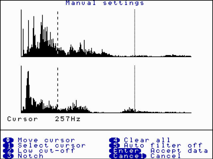
Manual settings allow the user to view the frequencies and set to the user preference.
The filter screen displays the frequencies heard at the two sensors in use. The bottom axis of
each graph displays the frequency level starting at 0Hz to the left. Two cursor lines are
displayed on each graph and are move by using the arrow keys. The longer dashed cursor
line is the current line selected to move. The lines on each graph will not cross. The position
of the current cursor line is displayed under the second graph, in this example 275Hz.
38
Press 1 (Select cursor) This toggles between the two cursor lines. Only the longer dashed
cursor line can be moved.
Press 2 (Low cut-off) When the left cursor line has be selected the low cut off option is
displayed. Move the left cursor to the required position and press 2. This will remove all
frequencies to the left of the cursor line. Removed frequencies are displayed in a cyan colour.
In this example the cursor was moved to 257Hz and a low cut off was selected, so all
frequencies from 0Hz to 257Hz will be removed.
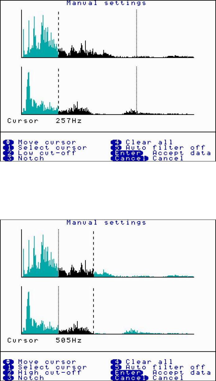
Press 2 (High cut-off) When the right cursor line is selected the high cut off option is
displayed. Move the right cursor to the required position and press 2. This will remove all
frequencies to the right of the cursor line. Removed frequencies are displayed in a cyan
colour. In this example the cursor was moved to 505Hz and high cut off was selected, so all
frequencies from 505Hz and above will be removed. By pressing ENTER to accept the data
would mean frequencies between 258Hz and 504Hz only are being used to process the
current correlation.
39
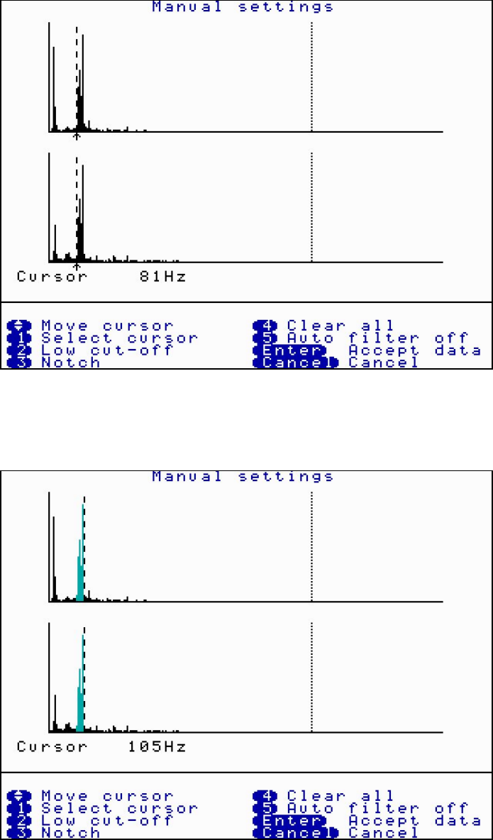
Press 3 (Notch) This options allows a “notch” of frequencys to be filtered out. Move the
selected cursor to the left of the area of frequency to be removed and press 3. A small arrow
appears under the graph. In this example 81Hz is selected.
Move the same cursor to the right of the area to be removed and press 3 again. In this
example 105Hz. The notch area of filtered out frequencys will change colour to cyan. The
current correlation will now ignore frequencys from 81Hz to 105Hz but will use all other
frequencys.
Press 4 (Clear all) This clears all filter settings currently set.
Press 5 (Auto Filter off) This will toggle between Auto Filter OFF and Auto Filter ON. At
present this option is under development and will be released on a future upgrade.
40
Program upgrade (Software and Firmware)
The MicroCorr Digital correlator and Out Stations have been designed so that their programs
can be upgraded as the latest developments take place.
The MicroCorr Digital Software is defined as the user interface within the base station, and
the Firmware describes the program that communicates between the correlator base station
and the Out Stations.
To upgrade the Software and/or Firmware a program must be installed on the PC. This is the
MCD Updater Application. The base unit requires both software and firmware to operate,
where as the Out Stations only require firmware to operate.
The application, the latest software and the latest firmware are all available as downloads
from the Palmer website www.palmer.co.uk/microcorr.htm
Once all the files have been downloaded to the PC start the MCD Updater Application and
follow the instructions as described below.
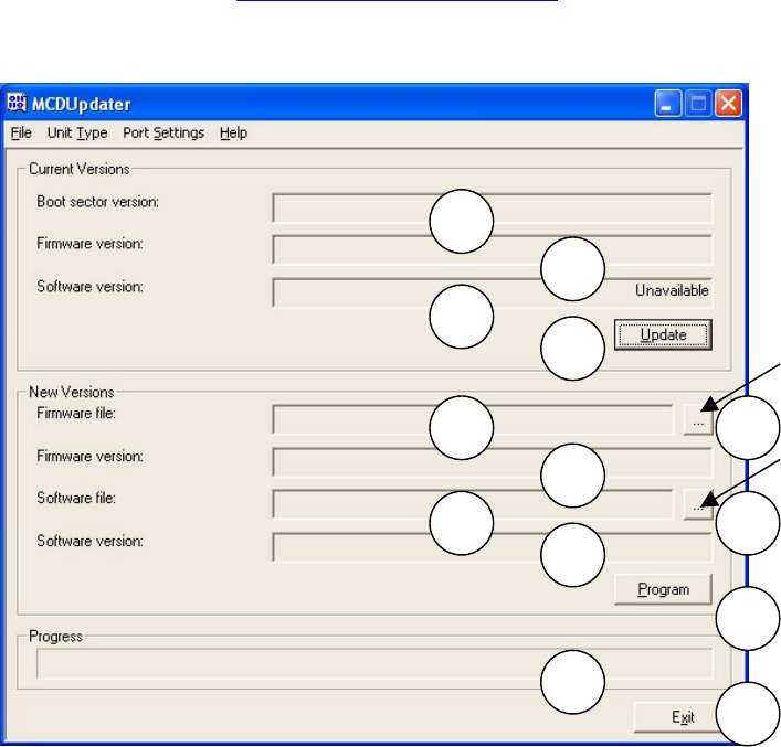
Screen description
The fields of the MCD Updater screen are described by number below.
Current System Information
1. This field gives the boot sector version within a base/out station and cannot be changed
by the user. It can only be used by Palmer engineers for system diagnostics.
2. This field gives the current firmware version within a base/out station.
3. This field gives the software version within a base station only, but will currently state
“Unavailable” before and after upgrading as the field is currently under development.
Note, this information can also be seen on the MicroCorr Digital information screen.
4. The ‘Update’ button is used to refresh the data in fields 1, 2 and 3.
1
2
3
4
5 6
7
8 9
10
11
12
13
Click to
browse
Click to
browse

41
Upgrade Information
5. This field gives the name and location of a firmware update file. These files have the
extension .mdf and contain the required information to upgrade a system’s firmware.
6. This button is used to ‘browse’ for a firmware update file on a local/network file system.
7. When a firmware file has been selected, this field displays version information about the
file. This allows the user to check that a newer version of firmware is being installed onto
the system.
8. This field gives the name and location of a software update file. These files have the
extension .mds and contain the required information to upgrade a system’s software.
9. This button is used to ‘browse’ for a software update file on a local/network file system.
10. This field displays version information about the file.
11. If there is a firmware and/or a software file selected clicking this button performs the
upgrade on the connected system.
12. This is a progress bar that indicates the progress of any running operation.
13. This button exits the application.
The File Menu
There is only one option in the file menu, which is ‘Exit’. Selecting this menu option closes the
MCD Updater application.
The Unit Type Menu
This menu allows the user to select the type of unit that is being programmed. The user can
either select ‘Base Station’ or ‘Out Station’.
The Port Settings Menu
This menu allows the user to select the communications port used by the MCDUpdater
application. In this menu there are 4 predefined options COM1 through COM4, and a user
defined port which allows the user to specify the port to use.
Important Notes for upgrading a MicroCorr Digital correlator (August 2003)
When using the upgrade program for the MCD the following points should be noted:
All of the correlation (.ked) files stored on the MicroCorr Digital will be deleted during the
upgrade operation. Therefore the user must save any required correlation files to a PC
before upgrading the software.
Once the upgrade procedure starts the power to the PC and the MCD should not be
interrupted, if it is the MCD will be rendered unusable.
1. Reboot your PC before starting, and ensure the Palmer Upgrade program is the only
application running, this ensures no other application can cause a break in the upgrade
procedure.
2. Ensure the MCD is connected to a charger that is switched on. This ensures a low battery
does not cause a shutdown.
3. Never try to interrupt the upgrade procedure once it is initiated.
42
Upgrading a Base Station
The following steps should be followed to upgrade the software/firmware within a base
station:
1. Connect the PC to the base station via the supplied serial cable.
2. Connect external power to the system. This ensures that the system does not power
down while the upgrade is in progress. Then back up all correlation files to the PC.
3. Start the MCDUpdater application and ensure that the ‘port’ is set correctly and ‘unit type’
is set to base.
4. Click on the ‘Update’ button to retrieve the current versions from the system.
5. Click on the ‘Browse Firmware’ and ‘Browse Software’ buttons and locate the firmware
and software update files. If only the software or the firmware is to be upgraded then only
select the required upgrade file.
6. Ensure that the update files are newer than those currently installed on the system. (The
latest version should always be used unless told specifically by your Palmer
representative that an older version should be used).
7. Click on the ‘Program’ button and wait for the operation to complete.
8. Remove the power and reset the system. Wait for the system to fully restart, then click on
the ‘Update’ button and verify that the software/firmware has updated successfully.
9. Switch the unit off completely and then switch back on again.
Upgrading an Out Station
The following steps should be followed to upgrade the firmware within an out station:
1. Connect the PC to the out station via the supplied serial cable.
2. Connect external power to the system. This ensures that the system does not power
down while the upgrade is in progress.
3. Start the MCD Updater application and ensure that the ‘port’ is set correctly and ‘unit type’
is set to Out Station.
4. Click on the ‘Update’ button to retrieve the current versions from the system.
5. Click on the ‘Browse Firmware’ button and locate the firmware update file.
6. Ensure that the update file is newer than that currently installed on the system. (The latest
version should always be used unless told specifically by your Palmer representative that
an older version should be used).
7. Click on the ‘Program’ button and wait for the operation to complete.
8. Remove the power and reset the system. Wait for the system to fully restart, then click on
the ‘Update’ button and verify that the firmware has updated successfully.
9. Remember to upgrade both red and blue Out Stations and, if purchased, the optional
yellow Out Station.
Upgrade verification
To verify the latest versions of software have been successfully installed, go to the main
menu on the correlator and select “5 Test and Service”. Then select “8 Information”. This
shows the Information screen, which lists the software and firmware versions.

43
Technical Specification
Base station
Process Full digital correlation
Frequency response 0.1 to 5000Hz
Filter selection Automatic Parametric Filtering
Manual setting if required
Resolution ±0.1m
Display Backlit colour ¼ VGA
Antennae External antenna/magmount
Mixed material 6 sections
Correlation files Up to 30 files stored
Plug-in memory upgrade for >200 files
Battery level indication For all system units
Battery type Rechargeable Lithium ion batteries, field
replaceable
Battery life >24 hours continuous use without backlight
14 hours continuous use with backlight
Key functions Combined correlation/survey mode
Listen (acoustic survey)
Frequency analysis
Peak suppression
Compute
Data replay for post processing
Velocity measurement (tricorrelation option)
User definable pipe types and velocities
Language Selectable via menu
Operating software User upgradable from www.palmer.co.uk
Printer output RS232 to parallel printer
PC download Via PC software, Windows compatible
Dimensions 220mm x 250 x 100mm
Weight 1.8Kg
Operating temperature -15°C to +50°C
Shock protection Drop tested to 1 metre
Environmental IP65
Enclosure Fully injection-moulded ABS
Connectors Military specification Amphenol
Diagnostics Self-test and auto-calibration on power-on
44
Out Station
Radio communication Single frequency digital transceiver
Radio frequency UHF (local regulations apply)
Controls ON/OFF (all functions remotely controlled
and monitored from Base station) with LED
status light
Connections Headphones
External antenna (if required)
Battery type Rechargeable Lithium ion batteries, field
replaceable
Battery life >18 hours
Hazard indication Flashing lights (2)
Antenna External antenna
Portability Integral sensor stowage
Integral cable wrap
Dimensions 210 x 145 x 305mm
Weight 1.6kg
Environmental IP68
Housing Fully injection-mouled ABS
Connectors Military specification Amphenol
Shock protection Drop tested to 1 metre
Sensor
Type Digital sensor with integral high strength
magnet
Frequency range 0.1 to 5000Hz
Dynamic range >90dB
Dimensions 180mm x 50mm diameter
Weight 1kg
Environmental IP68, rubber shroud for shock protection
Connection to Out Station 2m cable with strain relief
Military specification connector

45
Warranty
All equipment is warranted by Palmer Environmental Ltd to be free from defects in materials
and workmanship for a period of one year (unless otherwise stated) from the date of shipment
to the original customer. This warranty is only valid if the equipment has been installed and
used in the correct manner as described in this manual.
Repair or replacement (at Palmer Environmental’s option) will be made without charge
provided the above conditions have been met.
If any problems occur, notify Palmer Environmental Ltd or its authorised representative giving
full details of the problem, and the model and serial number of the equipment. You will
receive technical advice and/or shipping instructions depending upon the nature of the
problem.
Patents
Patents for the MicroCorr Digital are pending. MicroCorr is a registered trade-mark.
Note
Palmer Environmental reserves the right to change products, services or specifications
without notice.
Palmer Environmental Ltd
Ty Coch House
Llantarnam Park Way
Cwmbran
NP44 3AW
United Kingdom
Tel: +44 (0) 1633 489479
Fax: +44 (0) 1633 877857
email: info@palmer.co.uk
http://www.palmer.co.uk
Technical support: support@palmer.co.uk