Palmer Environmental MD MicroCorr Digital Leak Detector Out-Station User Manual MicroCorr 6 short form manual
Palmer Environmental Ltd MicroCorr Digital Leak Detector Out-Station MicroCorr 6 short form manual
Contents
- 1. User manual pt 1
- 2. User manual pt 2
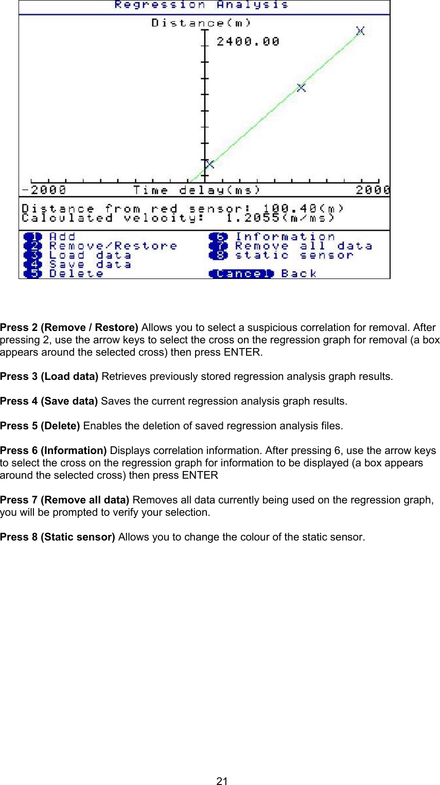
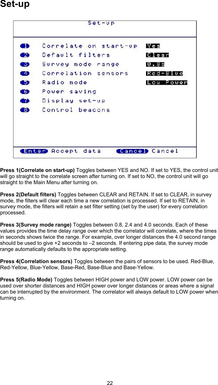
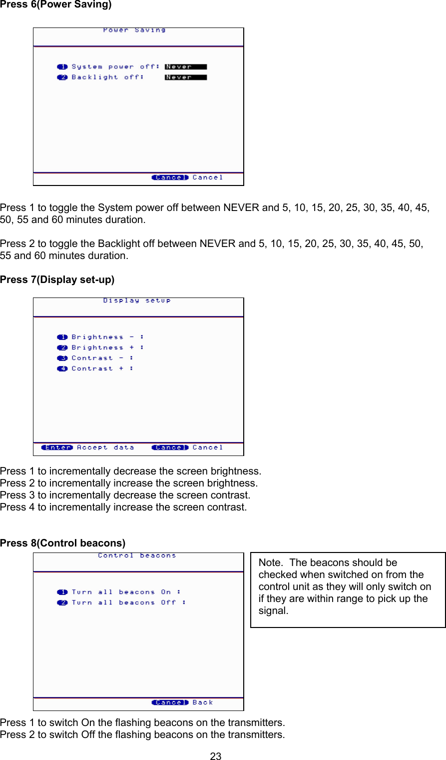
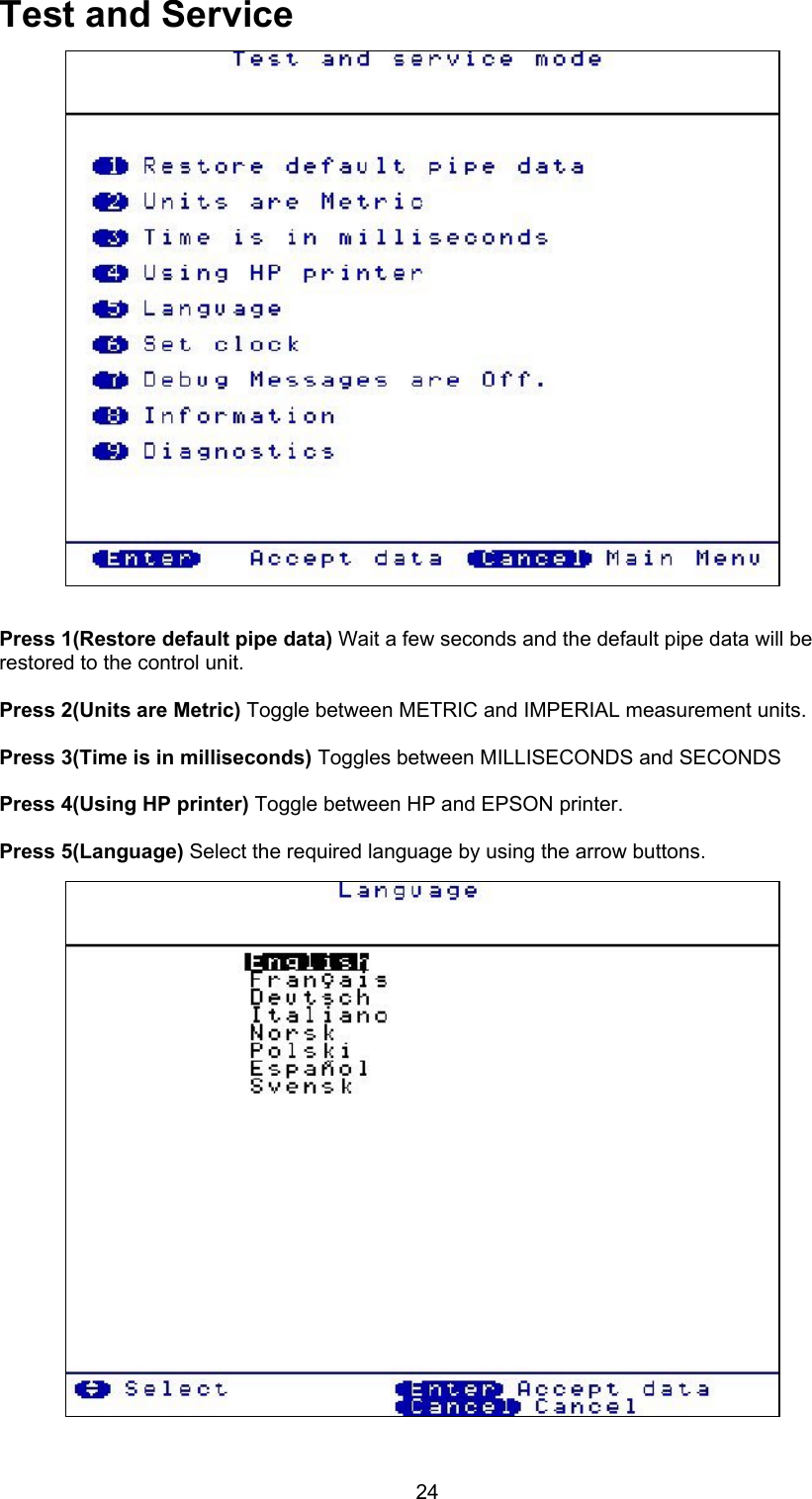
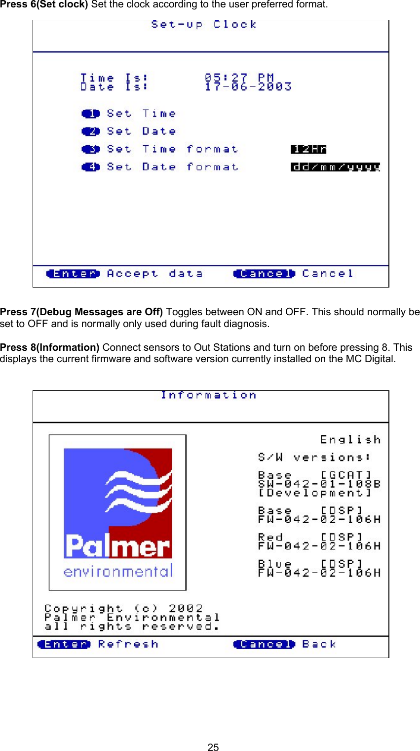
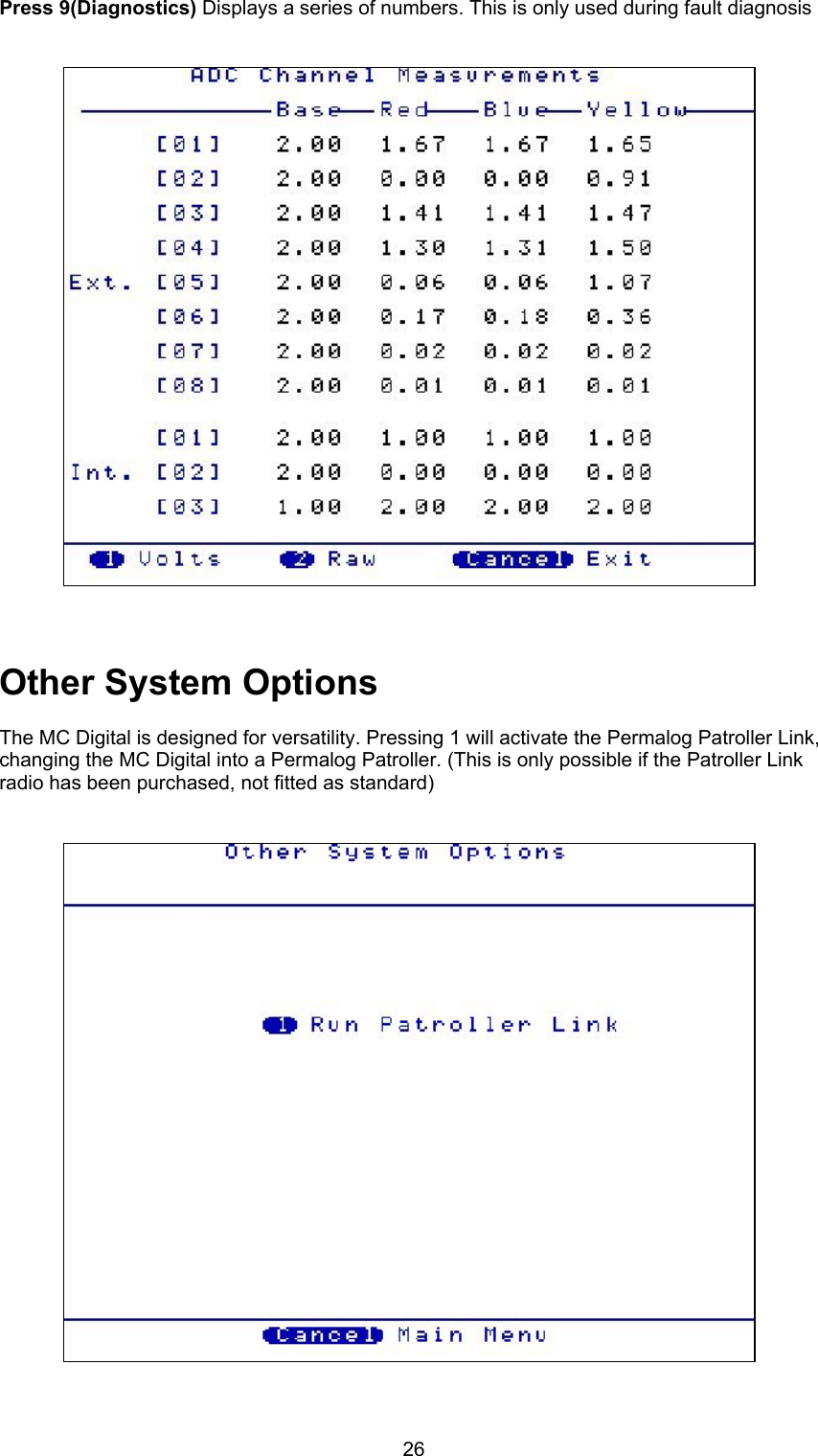
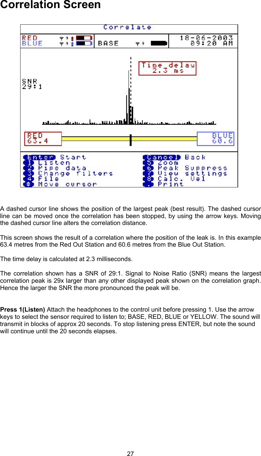
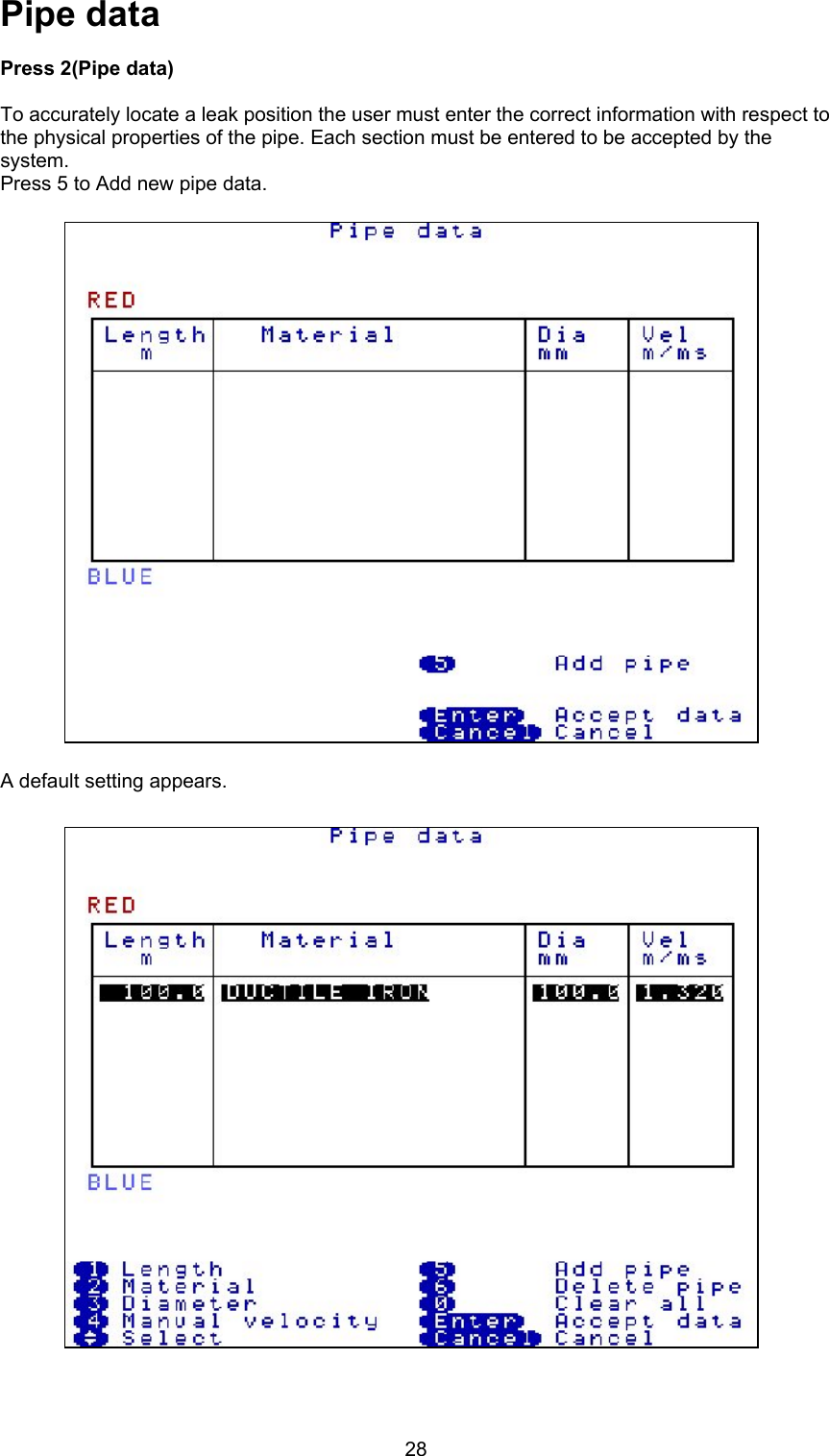
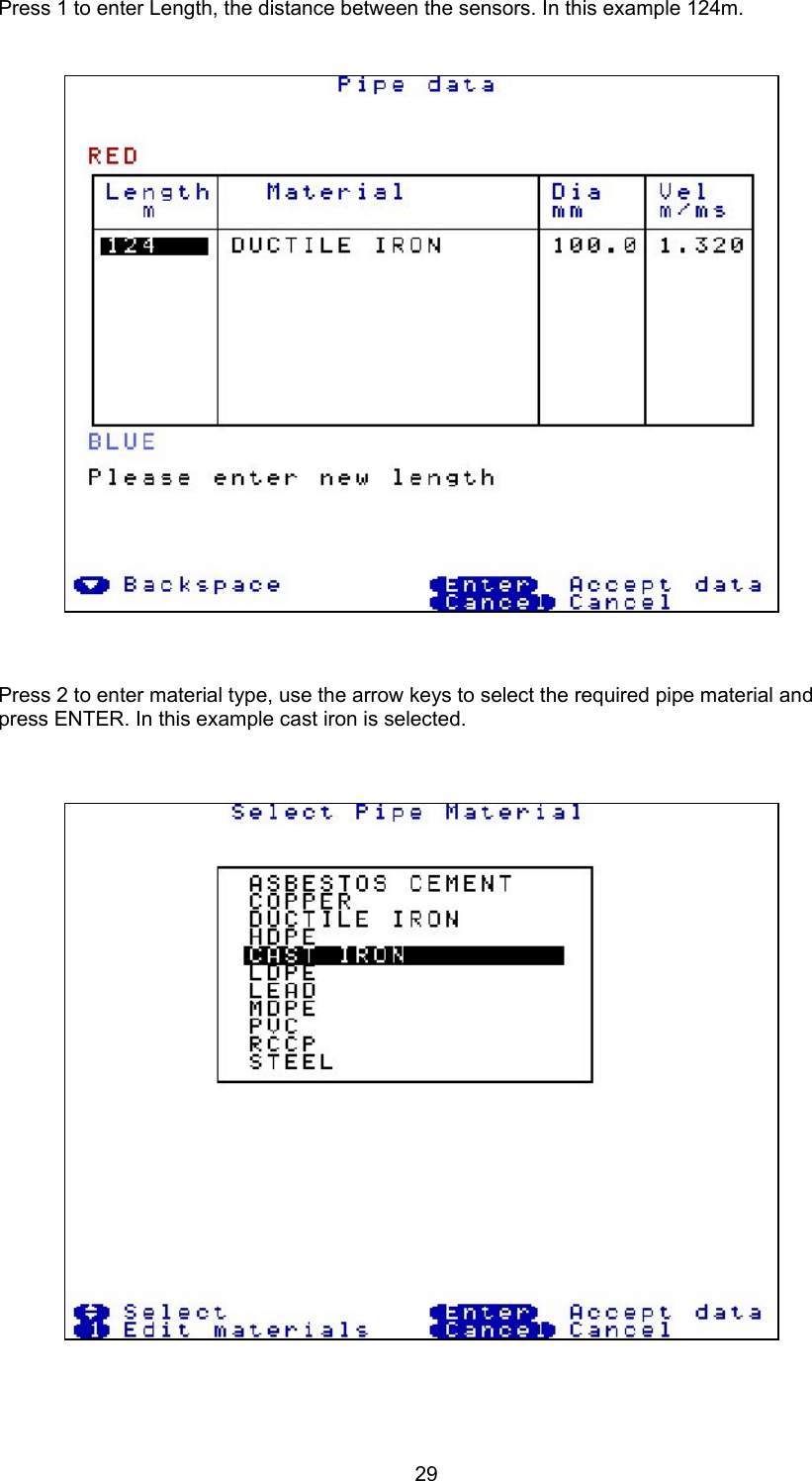
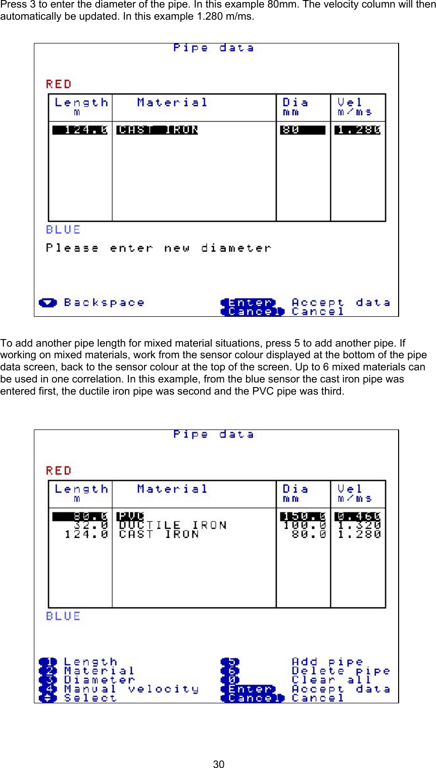
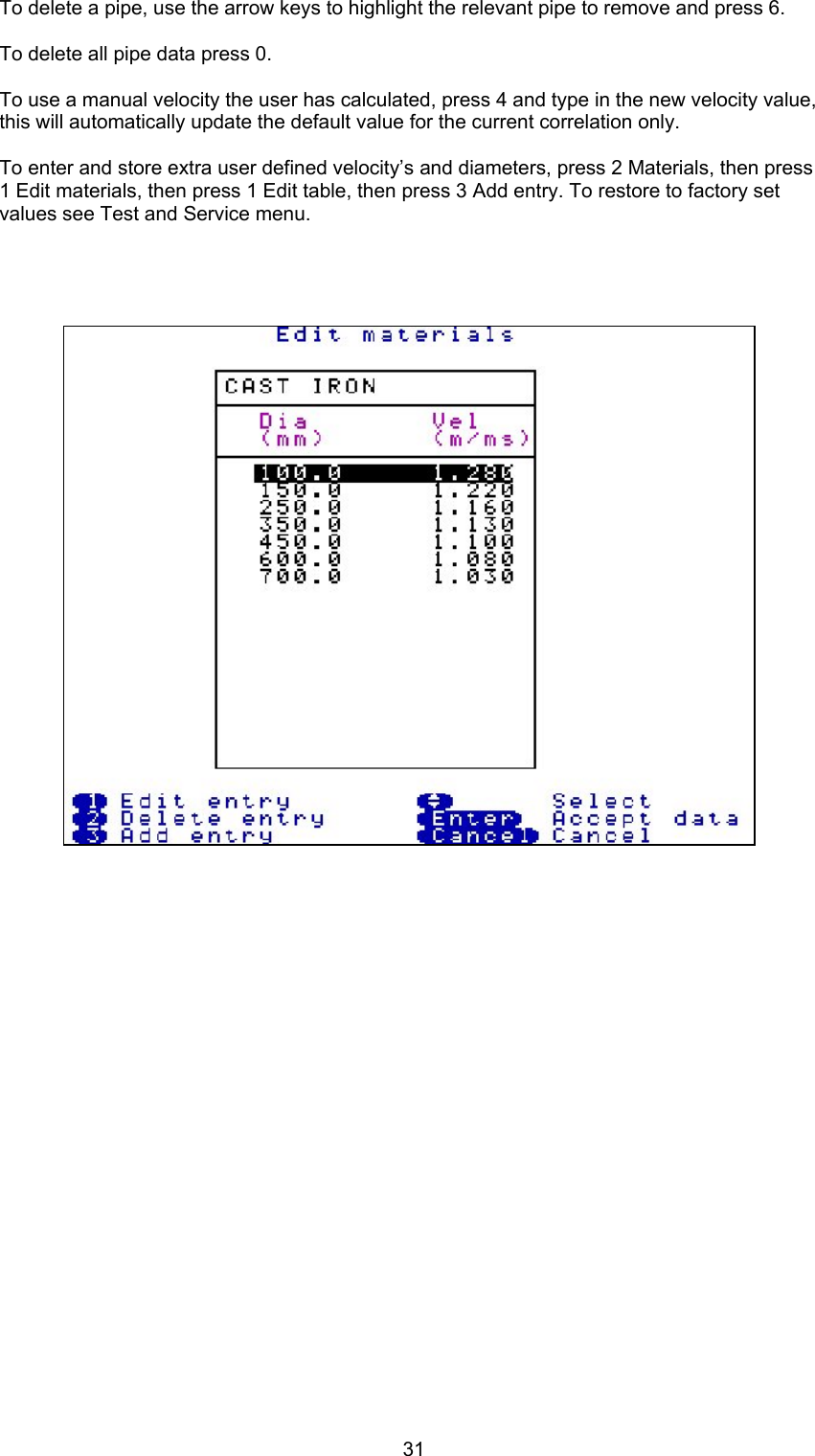
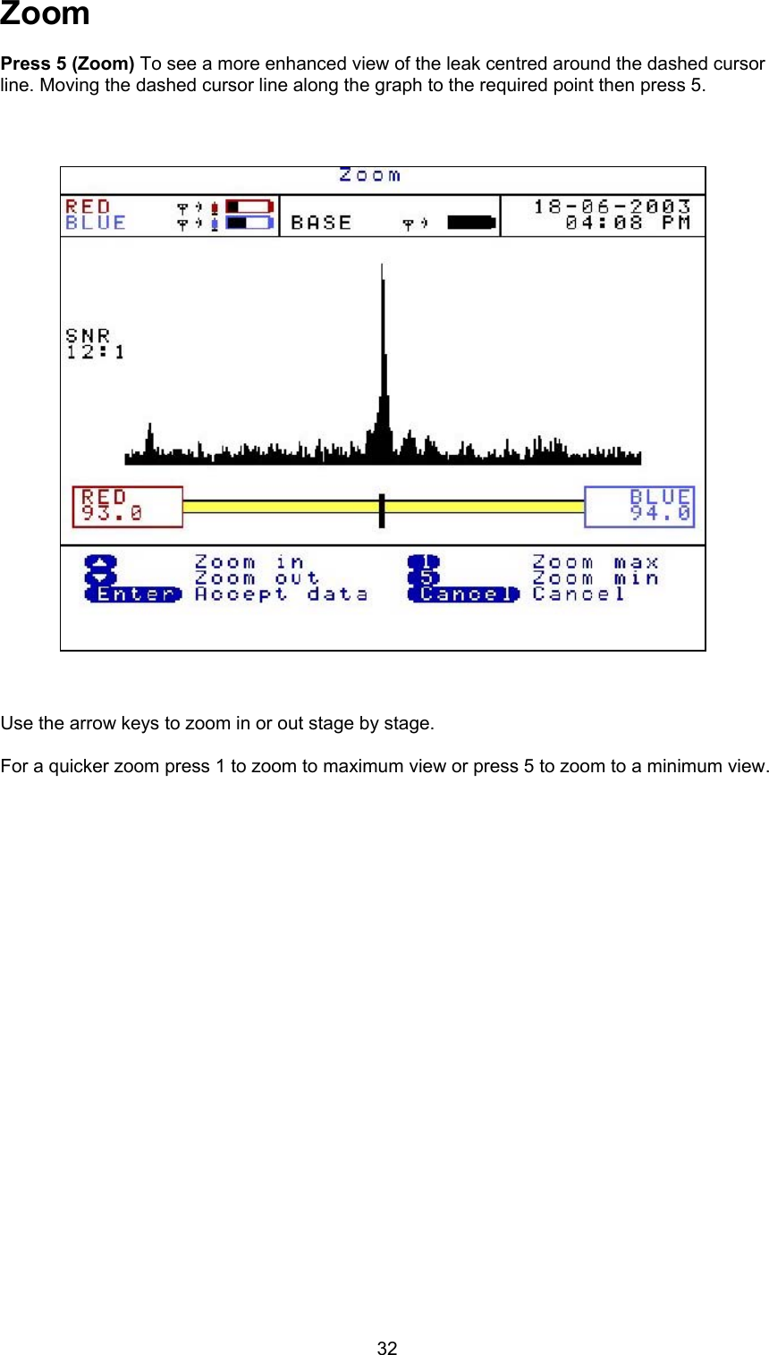
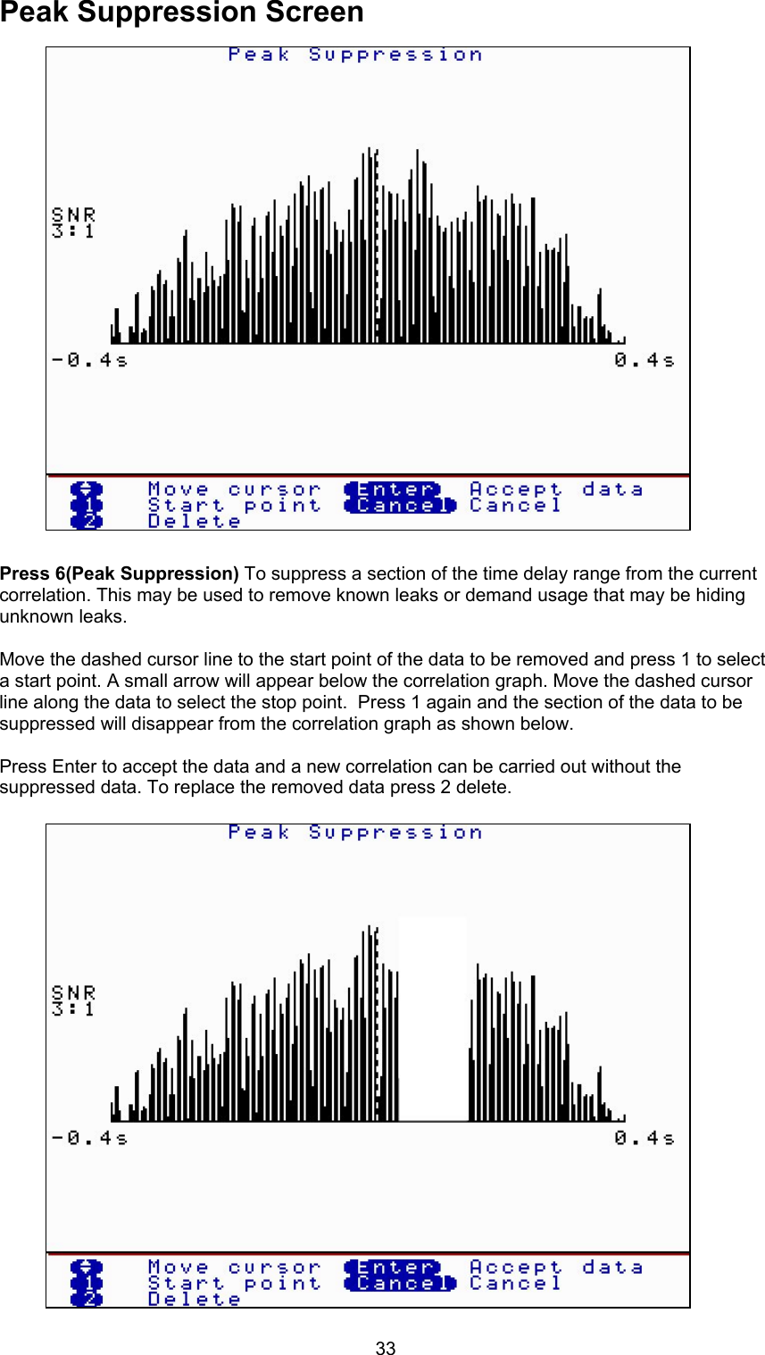
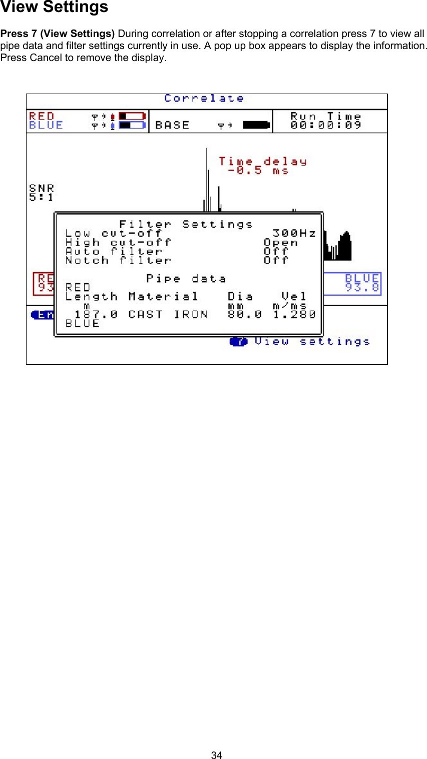
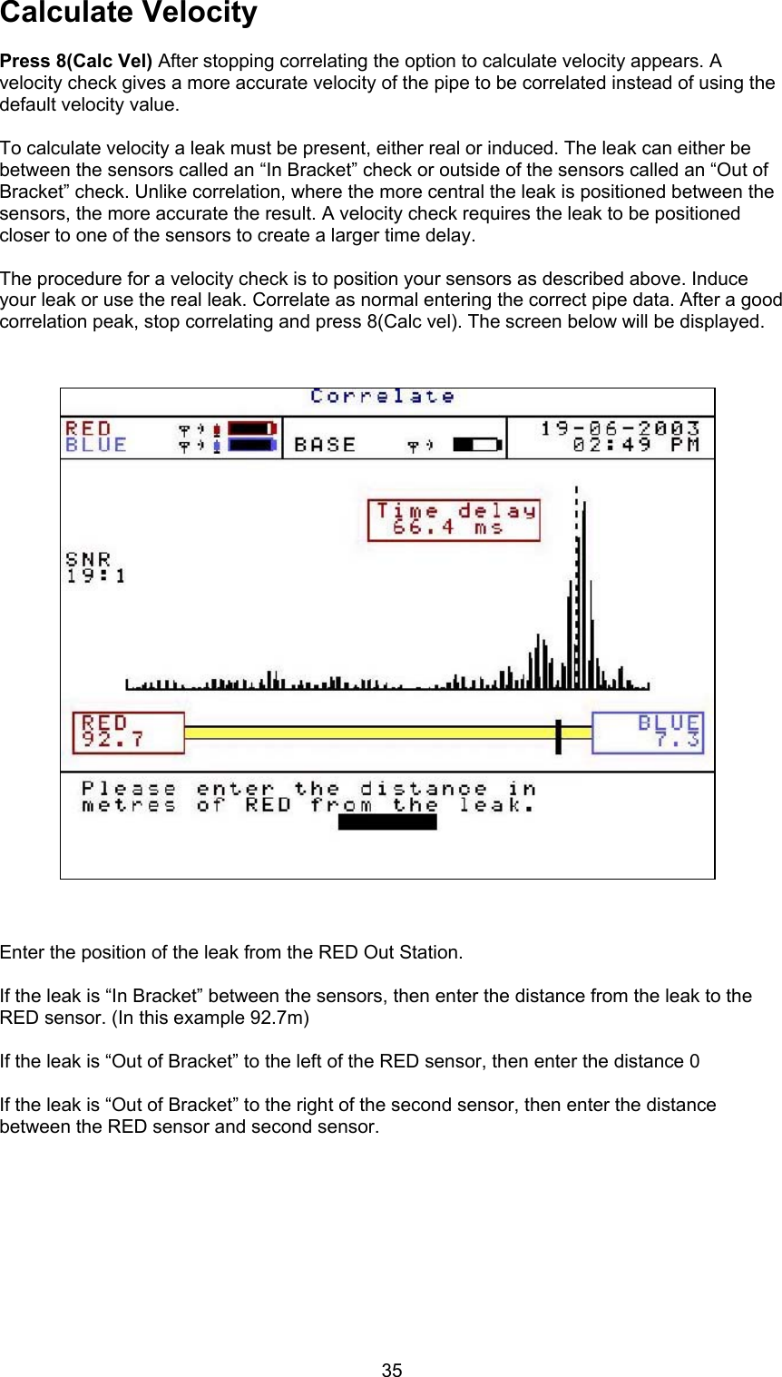
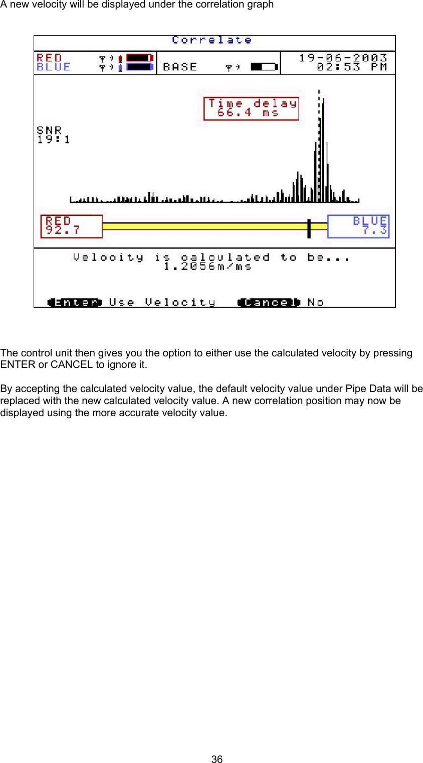
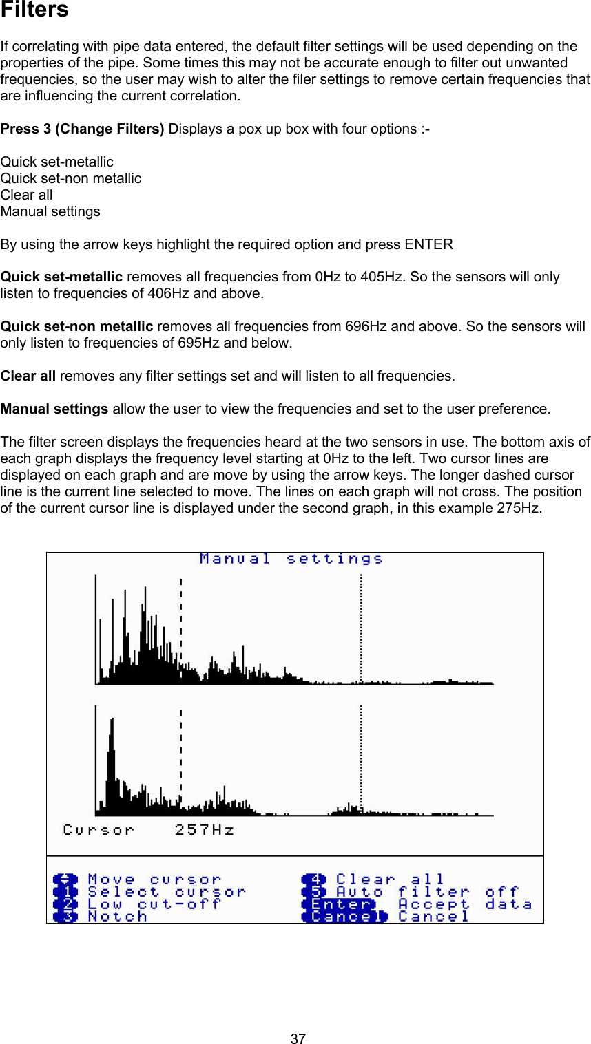
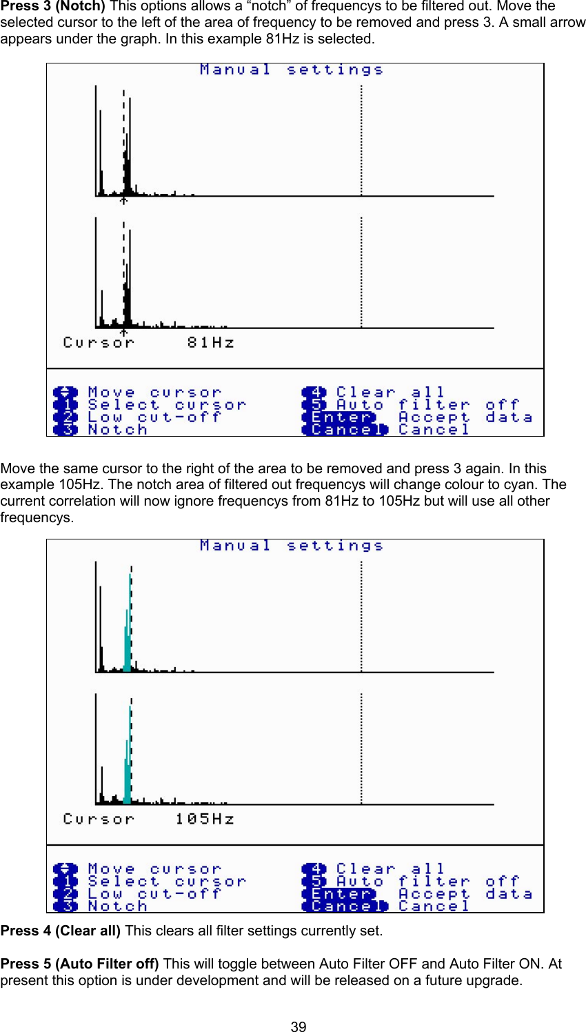
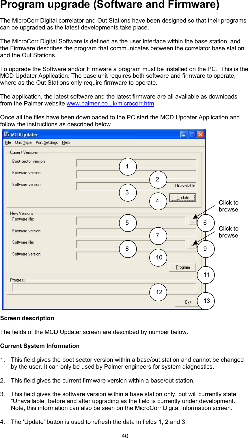
User manual pt 2