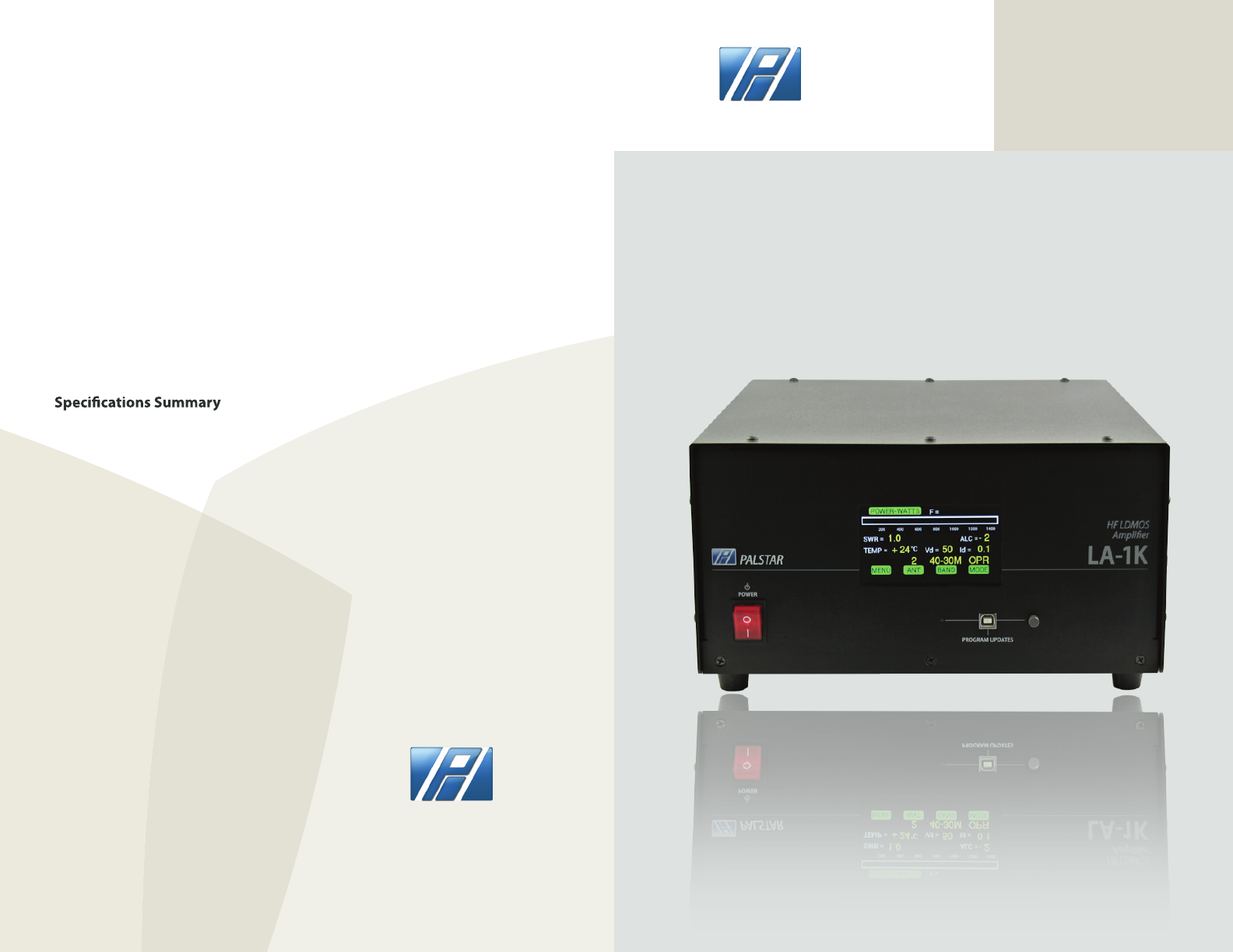
Palstar LA-1K Palstar LA-1K RF Sensing Dual HF LDMOS is a 1000W amplifier is a complete stand-alone amateur radio amplifier. User Manual 2
Palstar Inc Palstar LA-1K RF Sensing Dual HF LDMOS is a 1000W amplifier is a complete stand-alone amateur radio amplifier. Users Manual 2
Palstar >
Contents
- 1. Users Manual 1
- 2. Users Manual 2
Users Manual 2
Palstar products are designed by
Hams for Hams carrying on the
Palstar tradition for high-quality
products designed and
manufactured in Ohio, USA.
LA-1K RF SENSING 1000W
DUAL HF LDMOS AMPLIFIER
1000 watts PEP CW ICAS (160 m to 6m)
RF Sensing Auto Band Switcing
Color touch screen
Variable speed fans
12.75” x 6.25” x 16.5”
9676 N. Looney Rd,
Piqua, OH 45356 USA
(937) 773-6255
(800) 773-7931
(937) 773-8003 (Fax)
www.palstar.com
LA-1K RF SENSING 1000W
DUAL HF LDMOS AMPLIFIER
Technical Manual
Designed and Manufactured in the USA
Copyright 2017 Palstar, Inc.
PALSTAR
PALSTAR
OUPUT POWER: 1000 Watts PEP CW ICAS
CW MODE: Operates close to 50% of average power. It
is suggested that with power levels
up to 850W transmissions may be 5 minutes
on, 1 minute o.
FM/RTTY: 275 watts approx.
FREQUENCY RANGE: 1.8 TO 54 MHz
DISPLAY: Color touch screen
OUTPUT: 3 RF SO-239 connectors
ALC: Exciter power control
GAIN: 13+/-1dB (NOMINAL)
RF SENSING: Auto band switching
RF OUTPUT: Vacuum RELAY R/T Switching
POWER SUPPLY: Internal Medical grade
DC SUPPLY: 100VAC - 260 AC 50V@42A
POWER DEVICES: 2 x 5600H 600W (LDMOS)
INTERMOD: Low IMD Distortion >-35dB
PURE SIGNAL: Sample@+10dBm (Rear Panel)
COOLING: Variable Speed Fans (3 speed)
CHASSIS: .090 ga. aluminium
TOP COVER: .090 ga. aluminium, powder coated
DIMENSIONS: 12.75” W x 6.25“ H x 16.5” D
WEIGHT: 27 LBS, 12.25 Kg
DESIGN CONCEPT: Full compatibility with Palstar
HF-AUTO autotuner
WARRANTY: Two year
LA-1K SPECIFICATIONS
Page 14
Page 1
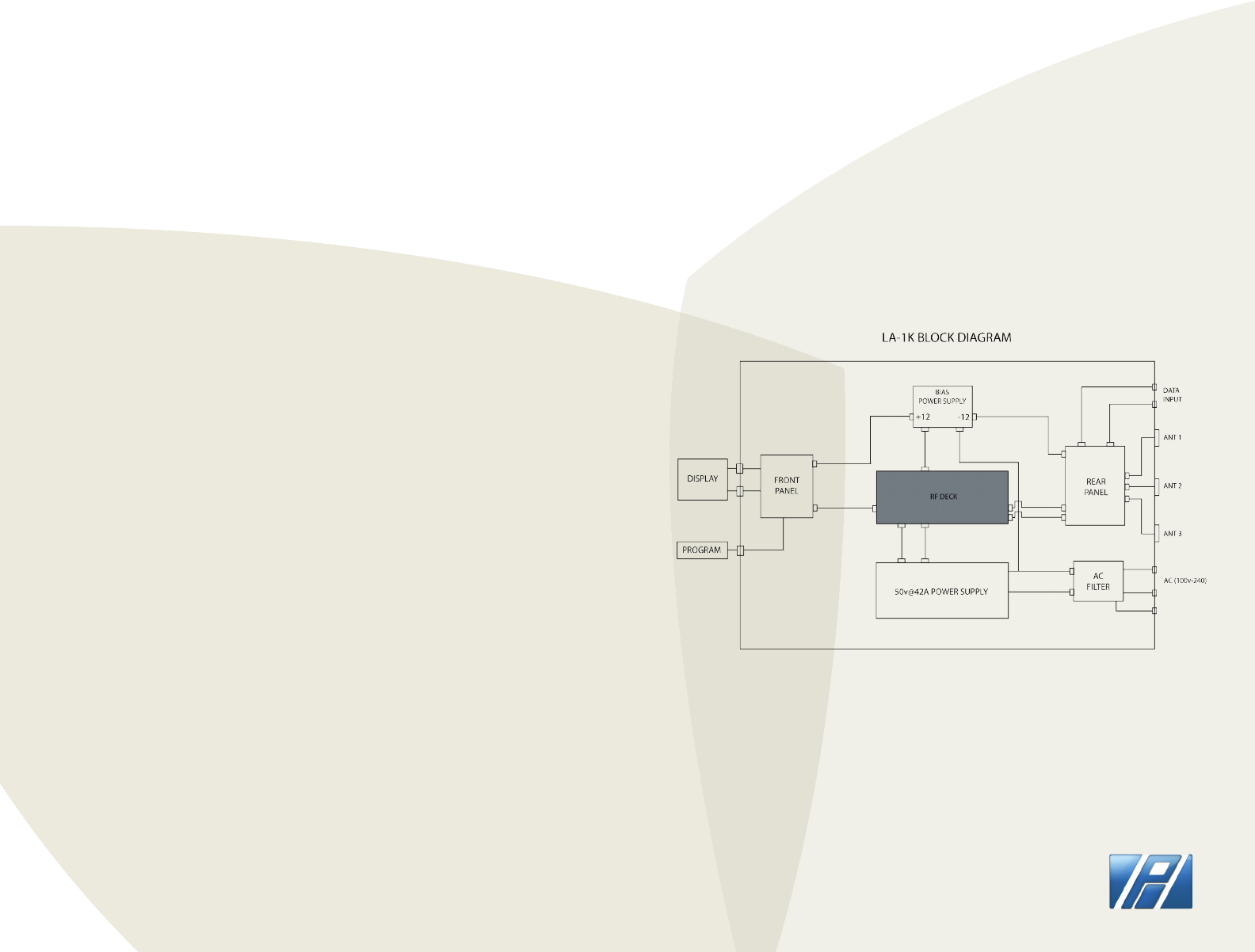
LA-1K BLOCK DIAGRAM
PALSTAR
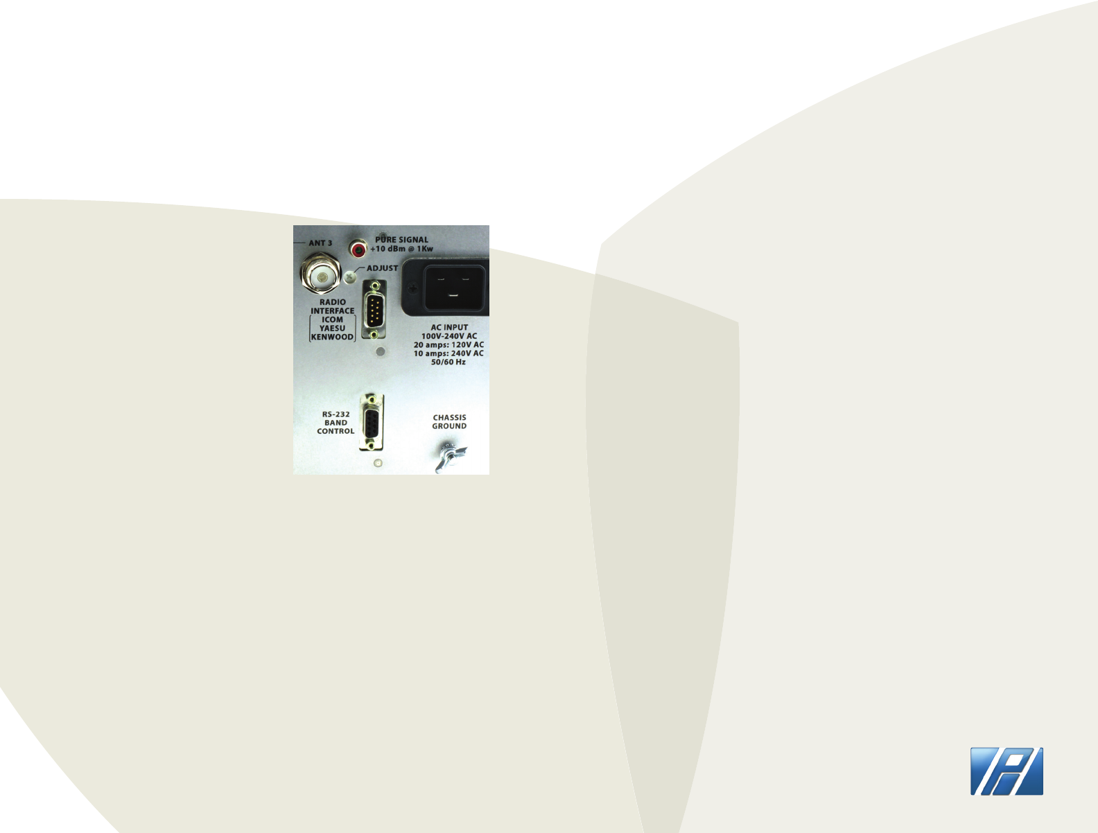
EXTERNAL DATA CONNECTORS
The LA-1K RF Sensing Dual HF LDMOS amplier is a complete
stand-alone amateur radio amplier.
It is completely independent of data from an external source to
determine frequency for tracking from Band to Band. As a result of this
feature, the LA-1K will function with any transmitting device without
interconnecting data cable attachments.
The power output of the LA-1K is 1000 Watts PEP CW ICAS (Intermittent
Commercial and Amateur Service). Under the ICAS classication, the
use of the LA-1K is designed for transmissions that are of an
intermittent nature.
Intermittent operation of the LA-1K implies that no operating or
“ON” period of 1000W of Continuous Carrier Power will exceed
1(ONE) minute.
On Single Side Band (SSB) voice duty there is no limit on transmit time
at full power of 1000W PEP.
Every “on” period must be followed by an “o” or standby period of at
least the same or longer duration.
The LA-1K provides a +10dBm@1kW RF tap feed at the rear panel to
provide provisions for “pure signal” operation provided by compatible
transceivers. The level adjustment is calibrated at the factory.
The LA-1K was designed to be fully compatible with the Palstar
HF-AUTO automatic antenna tuner.
Page 2
Page 13
THEORY OF OPERATION
PALSTAR
The LA-1K automatically selects bands and it is normally not necessary
to connect band data cables between your transceiver and the LA-1K
amplier.
RADIO INTERFACE CONNECTOR:
This connector is designed to be
pin for pin compatible with other
ampliers. The required cables are
widely available. They can be used
to connect to ICOM and YAESU
transceivers.
XCVR Interface
[Radio Interface Pin Out]
Pin Function
1 BCD B IN
2 BCD A IN
3 Kenwood RX (data in) [Null modem required]
4 Kenwood TX (data out)
5 Icom Band Data
6 GND
7 Amp-Key IN
8 BCD D IN
9 BCD C IN
RS232 BAND CONTROL CONNECTOR:
This connector is designed to be used with Kenwood transceivers for
band selection using a null modem adapter. It is also designed to
control the amplier from a computer.
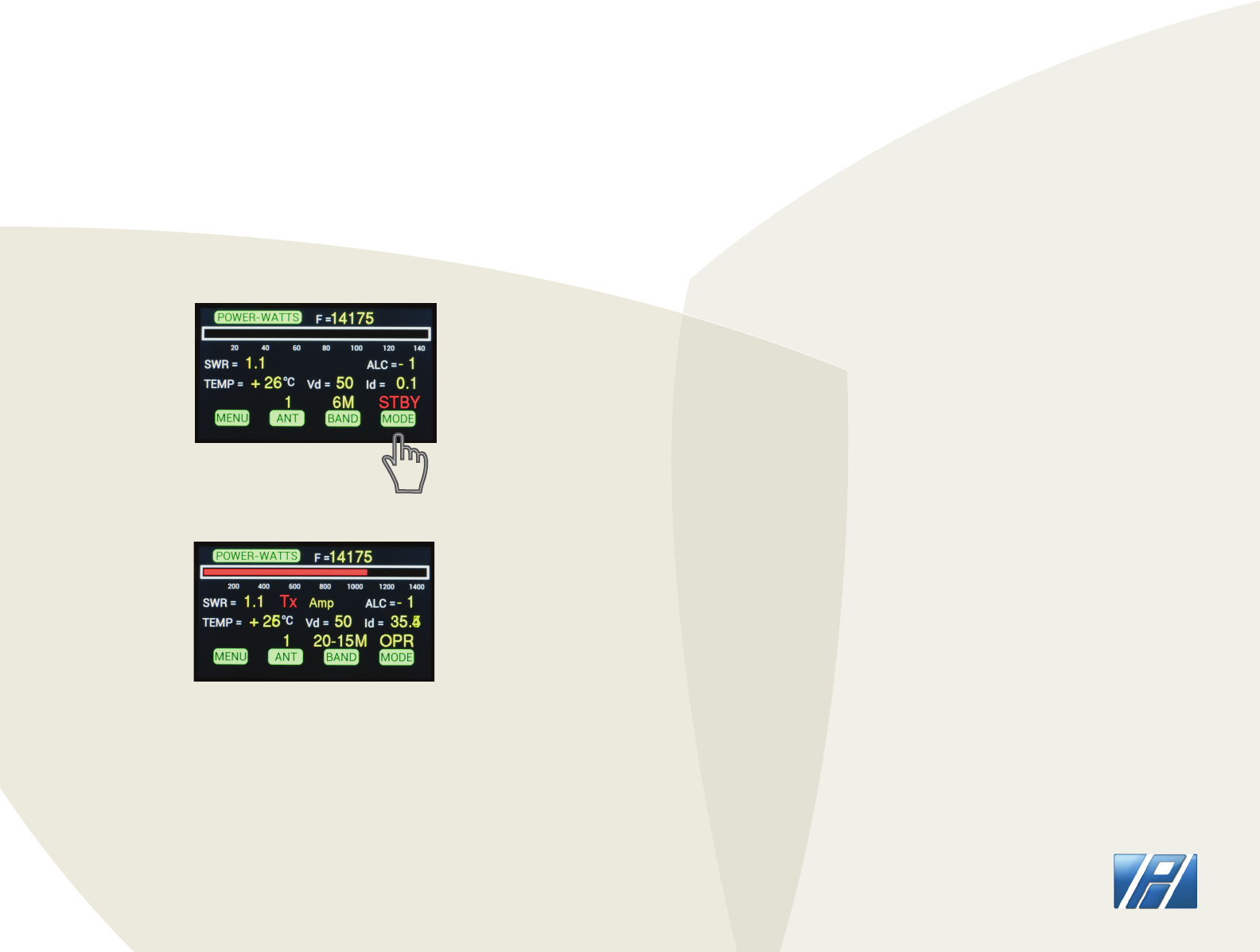
ON INITIAL POWER-UP
Display will indicate STBY mode (stand-by). To switch
mode press the “MODE” button on the tourchscreen
display to switch into “OPR” mode (operational).
SCREEN DISPLAY ON POWER-UP
Page 12
Page 3
HOW-TO UPDATE FIRMWARE
DOWNLOADING LA-1K FIRMWARE
CREATE a folder on your computer’s hard drive
NAME the folder LA_1KFIRMWARE
DOWNLOAD the Firmware le (Zip format) from the Palstar website,
http://www.palstar.com/en/la-1k/. The download link is near the bottom of
the page. The link to the le is named “LA-1K Firmware x.x”
SAVE the le to the folder you created in Step 1
OPEN the folder by right-clicking on the Zip le and select “Extract All” -
follow the steps in the Extraction wizard
CONNECT one end of the USB cable to a USB port on your computer.
DOUBLE-CLICK “LOAD_LA-1K” within your LA_1KFIRMWARE folder that you
created in Step 2.
Follow the instructions on the opened computer window and use the
"Browse" button to select the rmware version to be loaded.
Depress and hold down the GREY button to the right of the USB port
labeled “PROGRAM UPDATES” during the next two steps.
CONNECT the other end of the USB cable to a USB cable to the LA-1K front
panel.
TURN-ON the LA-1K. A "Found 1 device" message will appear on the right
side of the opened computer window.
Release the GREY button on the LA-1K front panel.
Click on the "Update Firmware" button that is on the opened computer
window. Wait until the green bar in the middle of the computer window
shows that the programming completes by lling from left to right. The
rmware version number on the LA-1K is on the bottom line of the start up
screen.
PALSTAR
STAND-BY MODE
OPERATIONAL MODE TRANSMITTING
NOTE: Wattmeter only shows RED power bar graphical
indicator when the LA-1K is transmitting.
Page 4
Page 11
OPERATIONAL MODE
LA-1K FIRMWARE SUMMARY
1.00H: As shipped from factory.
PALSTAR
OPERATIONAL MODE
OPERATIONAL MODE
To switch into Operational mode “OPR” press the “MODE”
button on the touchscreen display. The touchscreen
menu will display “OPR” mode (operational). The red
power bar graphical indicator will only be visible when
transmitting.
Page 10
Page 5 PALSTAR
OPERATIONAL MODE
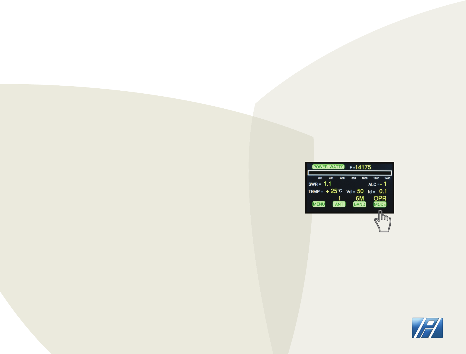
BAND SELECT
To switch bands, 160M-80M-40-30M-20-15M-12-10M-6M,
press the “BAND” button on the touchscreen display,
then select desired band. The LA-1K selects the proper
band automatically when transmit is activated.
ANTENNA SELECT
To switch antennas between ANT 1(Coax 1), ANT 2 (Coax
2), and ANT 3 (Coax 3), press the “ANT” button on the
touchscreen display, then select desired antenna ouput.
This setting will automatically select when changing
bands to the last one used on any particular band. The
default value is ANT 1.
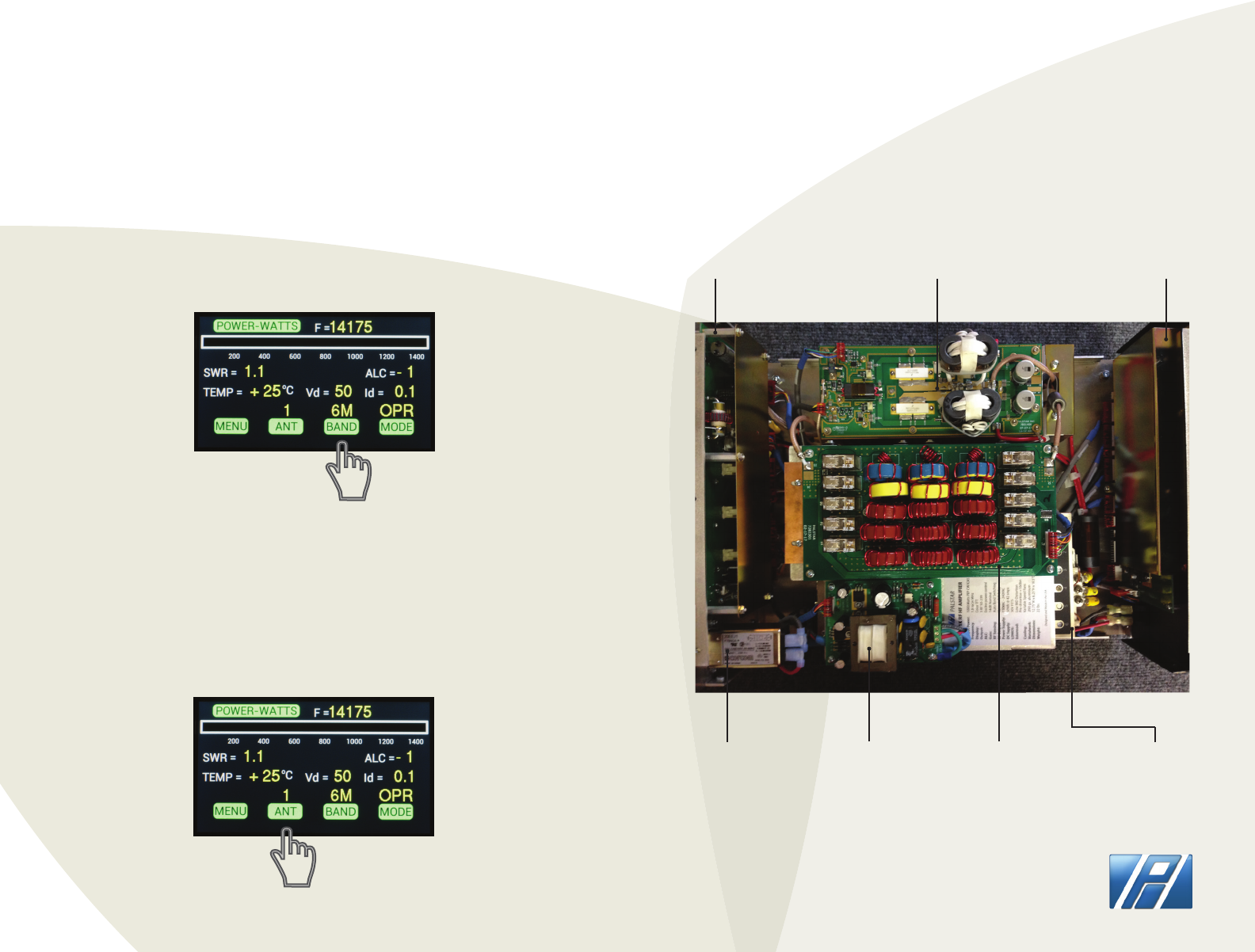
INTERIOR PHOTO
Rear Panel RF Deck Front Panel
AC input lter +/-12V (BIAS) +50V@42A
Power Supply
Dual output
lters
Page 6
Page 9
OTHER MENU OPTIONS OTHER MENU OPTIONS
PALSTAR
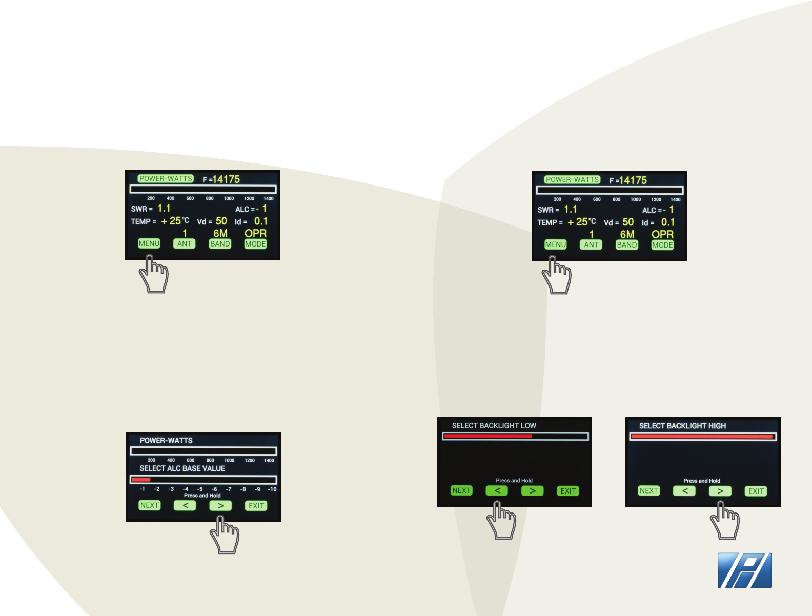
SELECT ALC BASE VALUE
To adjust ALC base value select menu on the touchscreen
display.
Press and hold the < or > arrows to increase or decrease
ALC BASE VALUE. If using ALC this should be adjusted
carefully to match your transceiver’s requirements
(usually -1.5V approximately).
ALC BASE VALUE
SELECT BACKLIGHT
To adjust the backlight on the touchscreen display press
MENU.
Press and hold the < or > arrows to adjust BACKLIGHT
LOW (screen intensity when no buttons are pressed) and
select NEXT and then < or > arrows to adjust BACKLIGHT
HIGH (screen intensity when buttons are being pressed).
SELECT BACKLIGHT LOW/HIGH
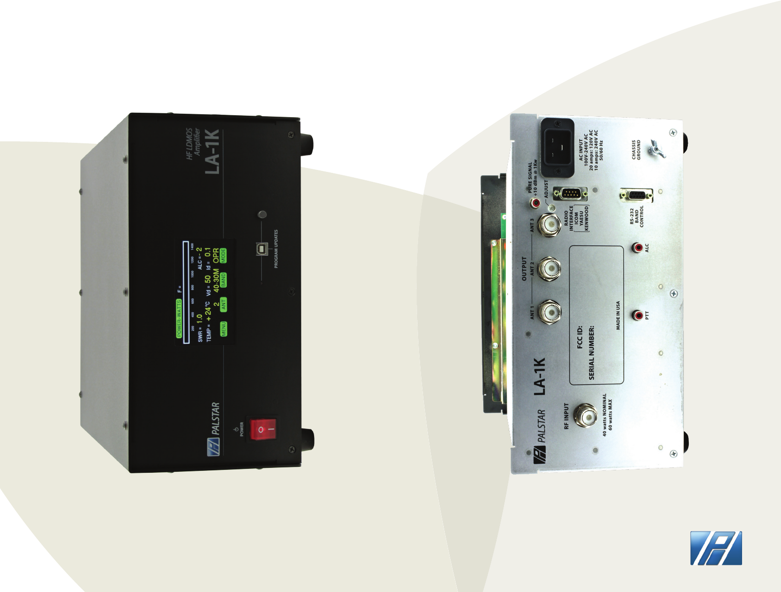
LA-1K Front & Rear Panel
Page 8
Page 7 PALSTAR