Panasonic Devices Europe 1740 Bluetooth Smart Module User Manual TABLE OF CONTENTS
Panasonic Industrial Devices Europe GmbH Bluetooth Smart Module TABLE OF CONTENTS
UserManual.wiki
>
Panasonic Devices Europe
>
1740 User Manual
15_PAN1740 UserMan
Navigation menu
Upload a User Manual
Namespaces
Wiki Guide
HTML
PDF
Info
Views
User Manual
Discussion / Help
Navigation
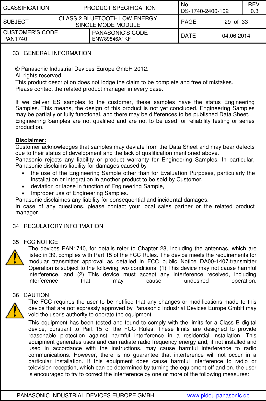
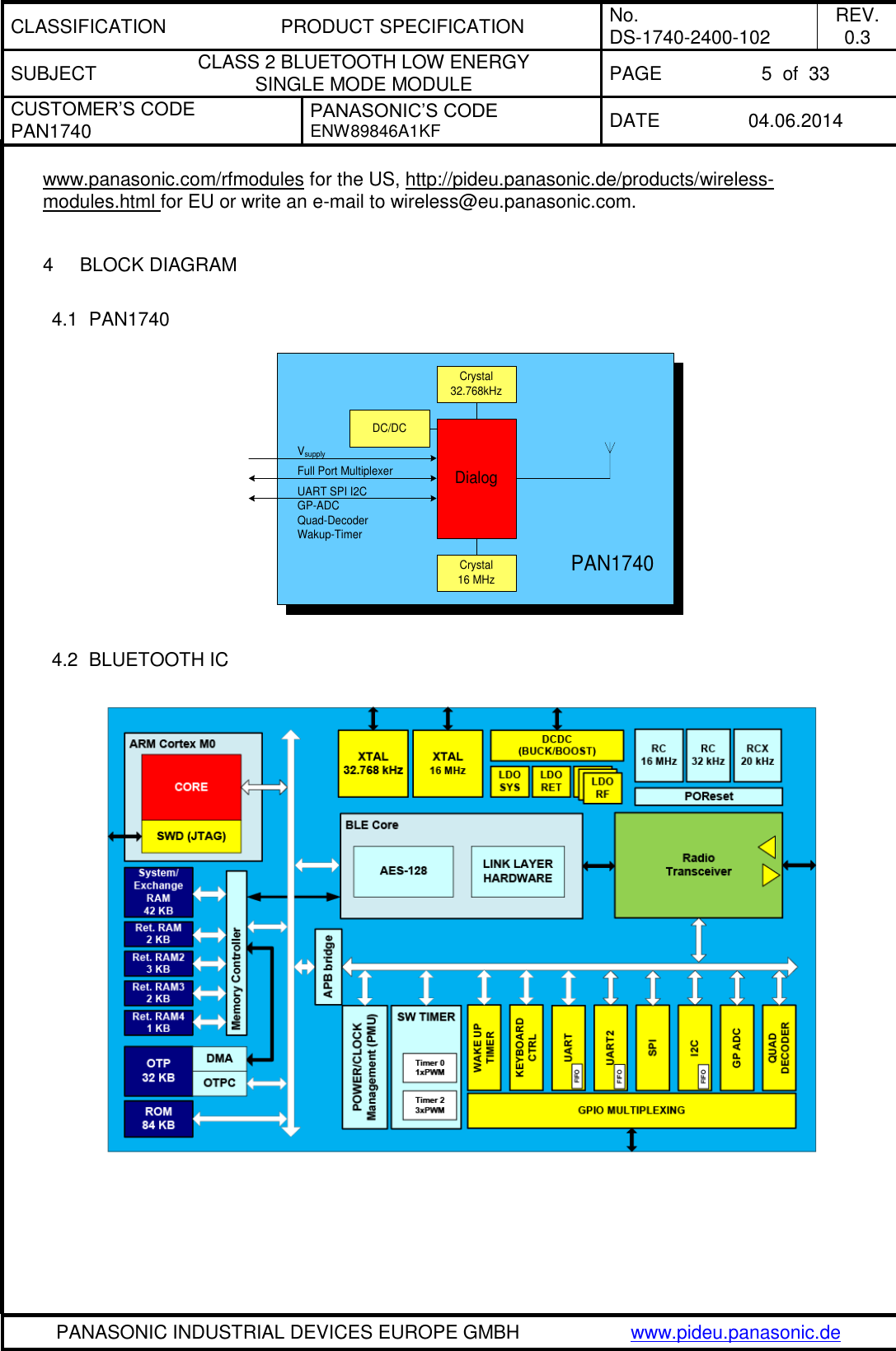
![CLASSIFICATION PRODUCT SPECIFICATION No. DS-1740-2400-102 REV. 0.3 SUBJECT CLASS 2 BLUETOOTH LOW ENERGY SINGLE MODE MODULE PAGE 4 of 33 CUSTOMER’S CODE PAN1740 PANASONIC’S CODE ENW89846A1KF DATE 04.06.2014 PANASONIC INDUSTRIAL DEVICES EUROPE GMBH www.pideu.panasonic.de 1 KEY FEATURES - Pre-programmed BT/MAC Address - Includes 16MHz and 32.768kHz crystal Crystal calibrated up to 1ppm - Single-mode Bluetooth Smart System-on-Chip - Programmable ARM CORTEX M0 CPU - Autonomous BTLE Stand Alone Operation - Bluetooth v4.1 (LE) embedded GATT profile – Low Energy Single Mode - Small 9.0 x 9.5 x 1.8 mm SMD package with antenna - Temperature Range from -40°C to +85°C - Peak Power consumption 4.9mA Rx and Tx - Less than a few µA in low power modes - Link budget 93dBm (Rx Sensitivity -93, Tx 0 dBm) - Integrated shielding to resist EMI - No external components needed 2 BLUETOOTH LOW ENERGY Bluetooth Low Energy (BLE), also called Bluetooth Smart, is a part of Bluetooth Ver. 4.0, BT v4.0 covers both BLE as well as Classic Bluetooth v2.1 and v3.0. Bluetooth Low Energy (BLE) is not backwards compatible with previous Classic Bluetooth standards (v2.1+EDR or v3.0). Dual mode Bluetooth v4.0 is targeted to gateway products and backwards compatible, but is not practical for low power devices. Bluetooth® 4.1 is an evolutionary update to the Bluetooth Core Specification. It rolls up adopted Bluetooth Core Specification Addenda (CSA1, 2, 3 & 4) while adding new features and benefits. Bluetooth 4.1 improves usability for consumers, empowers innovation for product developers and extends the technology’s foundation as an essential link for the Internet of Things. For more more details please see the BLUETOOTH® 4.1 QUICK REFERENCE GUIDE from Bluetooth SIG [1] 3 DESCRIPTION FOR THE MODULE The PAN1740 is a short-range BLE single mode module for implementing Bluetooth functionality into various electronic devices. PAN1740 is fully compliant with the Bluetooth V4.1 standard. It includes dedicated hardware for the Link Layer implementation of Bluetooth®Smart and interface controllers for enhanced connectivity capabilities. Please contact your local sales office for further details on additional options and services:](https://usermanual.wiki/Panasonic-Devices-Europe/1740/User-Guide-2328965-Page-4.png)
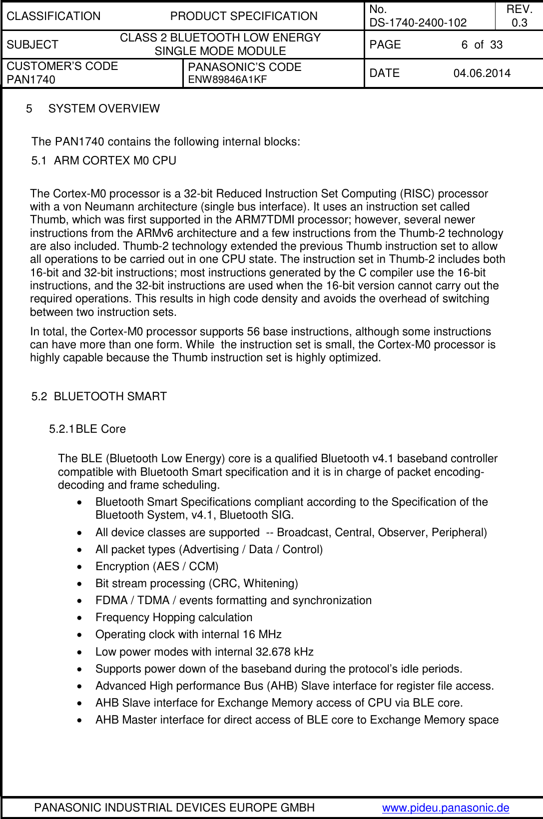
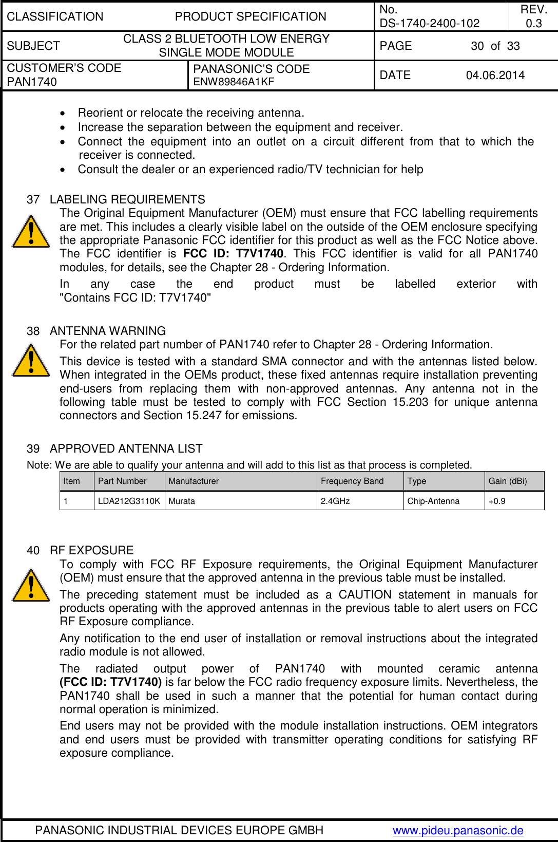
![CLASSIFICATION PRODUCT SPECIFICATION No. DS-1740-2400-102 REV. 0.3 SUBJECT CLASS 2 BLUETOOTH LOW ENERGY SINGLE MODE MODULE PAGE 13 of 33 CUSTOMER’S CODE PAN1740 PANASONIC’S CODE ENW89846A1KF DATE 04.06.2014 PANASONIC INDUSTRIAL DEVICES EUROPE GMBH www.pideu.panasonic.de 8.6 KEYBOARD CONTROLLER The keyboard controller can be used for debouncing the incoming GPIO signals when implementing a keyboard scanning engine. It generates an interrupt to the CPU (KEYBR_IRQ). In parallel, five extra interrupt lines can be triggered by a state change on 32 selectable GPIOs (GPIOx_IRQ). Features Monitors any of the 12 available GPIOs Generates a keyboard interrupt on key press or key release Implements debouncing time from 0 up to 63 ms Supports five separate interrupt generation lines from GPIO toggling 8.7 INPUT/OUTPUT PORTS The PAN1740 has software-configurable I/O pin assignment, organized into ports Port 0, Port1. Features Port 0: 8 pins, Port 1: 6 pins (including SW_CLK and SWDIO) Fully programmable pin assignment Selectable Push-pull or open drain per pin Selectable 25KOhm pull-up, pull-down resistors per pin Pull-up voltage VBAT3V (BUCK mode) Fixed assignment for analog pin ADC[3:0] Pins retain their last state when system enters the Extended or Deep Sleep mode. 8.8 TIMERS For any software related description please refer to the according Dialog document. 8.9 RESET The PAN1740 comprises an RST pad which is active high. It contains an RC filter for spikes suppression with 400 kΩ and 2.8 pF for the resistor and the capacitor respectively. It also contains a 25 kΩ pulldown resistor. This pad should be connected to ground if not needed by the application. The typical latency of the RST pad is in the range of 2 µs.](https://usermanual.wiki/Panasonic-Devices-Europe/1740/User-Guide-2328965-Page-13.png)

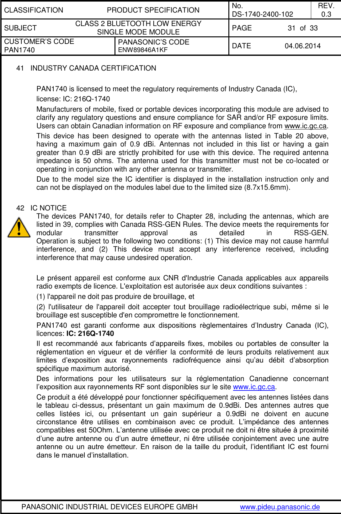
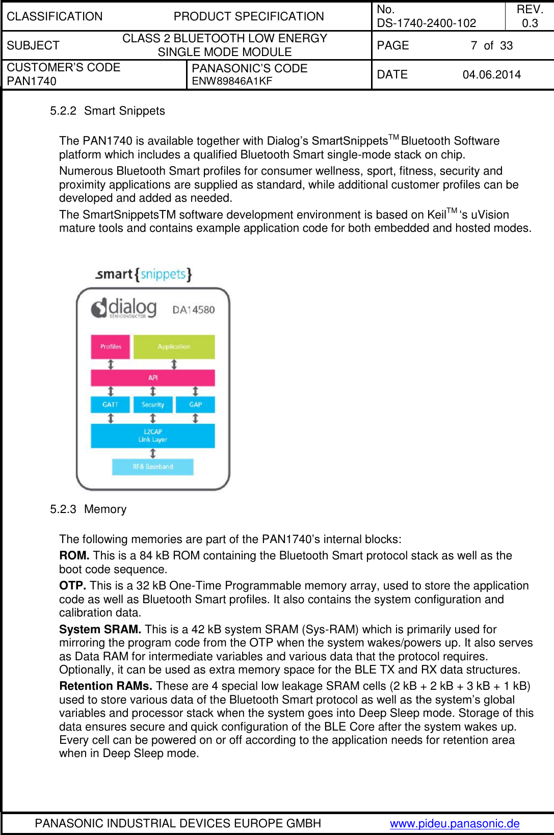
![CLASSIFICATION PRODUCT SPECIFICATION No. DS-1740-2400-102 REV. 0.3 SUBJECT CLASS 2 BLUETOOTH LOW ENERGY SINGLE MODE MODULE PAGE 26 of 33 CUSTOMER’S CODE PAN1740 PANASONIC’S CODE ENW89846A1KF DATE 04.06.2014 PANASONIC INDUSTRIAL DEVICES EUROPE GMBH www.pideu.panasonic.de 26 LABEL FOR PACKAGE The picture shows an example from similar product. PAN1315Customer Code ENW89818C2JF105 mm51 mm (1T) Lot code [YYWWDLL] Example from above: YY year printed 08 WW normal calendar week printed 01 D day printed 5 (Friday) L line identifier, if more as one printed 1 L lot identifier per day printed 1 (1P) Customer Order Code, if any, otherwise company name will be printed (2P) Panasonic Order Code: (9D) Date code as [YYWW] (Q) Quantity [XXXX], variable max. 1500 (HW/SW) Hardware /Software Release Hardware 01 Indicates the HW revision. Software 01 Indicates the SW revision. 27 TOTAL PACKAGE barcodelabelmoisture-sensitive print(already exist on barrier bag) barcodelabeldesiccant 1) 2)moisture indicatorbarrier bagsealedinner carton boxsize 340 x 340 x 41 mm³1) quantity of desiccant according to calculation2) optional: desiccant placed into the corner of the barrier bag](https://usermanual.wiki/Panasonic-Devices-Europe/1740/User-Guide-2328965-Page-26.png)
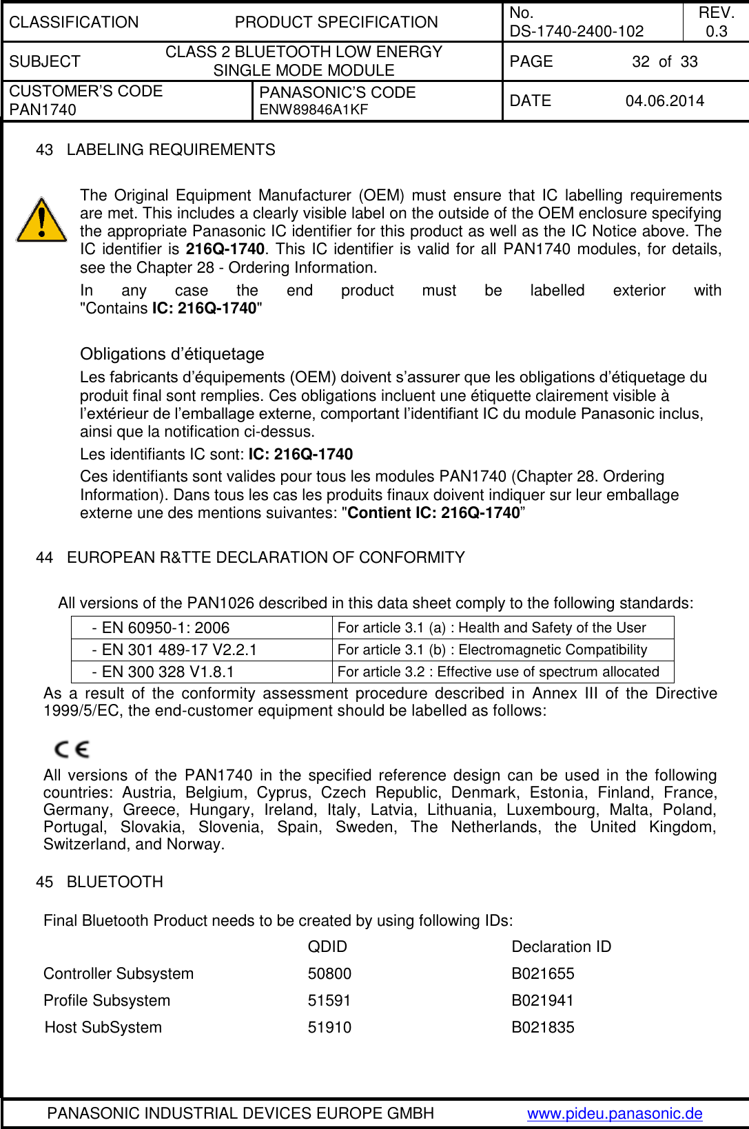
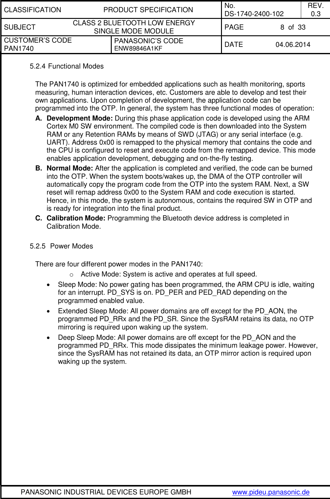
![CLASSIFICATION PRODUCT SPECIFICATION No. DS-1740-2400-102 REV. 0.3 SUBJECT CLASS 2 BLUETOOTH LOW ENERGY SINGLE MODE MODULE PAGE 27 of 33 CUSTOMER’S CODE PAN1740 PANASONIC’S CODE ENW89846A1KF DATE 04.06.2014 PANASONIC INDUSTRIAL DEVICES EUROPE GMBH www.pideu.panasonic.de 28 ORDERING INFORMATION Ordering part number Description MOQ (1) ENW89846A1KF (2) PAN1740 CLASS 2 Bluetooth single mode Module according BT-4.0. Bluetooth® smart device 1500 Notes: (1) Abbreviation for Minimum Order Quantity (MOQ). The standard MOQ for mass production is 1500 pieces, fewer only on customer demand. Samples for evaluation can be delivered at any quantity via the distribution channels. (2) Samples are available on customer demand 29 ROHS AND REACH DECLARATION Hereby we declare to our best present knowledge based on declaration of our suppliers that this product follows the latest official RoHS and REACH Directive. For the full declaration, please refer to [4].](https://usermanual.wiki/Panasonic-Devices-Europe/1740/User-Guide-2328965-Page-27.png)
![CLASSIFICATION PRODUCT SPECIFICATION No. DS-1740-2400-102 REV. 0.3 SUBJECT CLASS 2 BLUETOOTH LOW ENERGY SINGLE MODE MODULE PAGE 28 of 33 CUSTOMER’S CODE PAN1740 PANASONIC’S CODE ENW89846A1KF DATE 04.06.2014 PANASONIC INDUSTRIAL DEVICES EUROPE GMBH www.pideu.panasonic.de 30 DATA SHEET STATUS This data sheet contains the preliminary specification. Panasonic reserves the right to make changes at any time without notice in order to improve design and supply the best possible product. Please consult the most recently issued data sheet before initiating or completing a design. The datasheet is not public on the Panasonic webpage yet. 31 HISTORY FOR THIS DOCUMENT Revision Date Modification / Remarks 0.1 February 2014 1st preliminary version. 0.2 April 2014 Included Bluetooth 4.1 compliance. 0.3 June 2014 Formating Table 5. Updated Key Features. 32 RELATED DOCUMENTS For an update, please search in the suitable homepage. [1] BLUETOOTH® 4.1 QUICK REFERENCE GUIDE: https://www.bluetooth.org/en-us/specification/adopted-specifications [2] Semiconductor Website and Software Tools: http://support.dialog-semiconductor.com/ [3] Application Note Land Grid Array http://www.pideu.panasonic.de/pdf/184ext.pdf [4] REACH and RoHS Certificate http://www.pideu.panasonic.de/pdf/182ext2.jpg](https://usermanual.wiki/Panasonic-Devices-Europe/1740/User-Guide-2328965-Page-28.png)