Panasonic Healthcare 9TB099DSS DDS Backup Library User Manual 1U Sfy
Panasonic Healthcare Co., Ltd. DDS Backup Library 1U Sfy
users manual

DDS BACKUP LIBRARY
LKM-S121-S
SAFETY INSTRUCTION MANUAL
Please read through these instructions before operating this unit.
SPECIFICATION SUMMARY
GENERAL PERFORMANCE
➀ Power rating 120 – 240 V ~ AUTO
0.5 – 0.28 A 50 / 60 Hz
➁ Dimensions (W x H x D) 430 x 44 x 650 mm
➂ Weight 11.5 kg [ typical ]
➃ Temperature Operating: 5~40 °C Non-operating: – 40~65 °C
➄ Humidity Operating: 20~80 %RH Non-operating: 0~90 %RH
(Max. wet bulb temp. is 26 °C, Non-condensation) (Non-condensation,
No cartridge tape)
ENVIRONMENTAL CONDITIONS
Weight and dimensions shown are approximate.
Specifications are subject to change without notice.
LMQT00644 Printed in Japan
Rev.A
IMPORTANT SAFETY NOTICE
LMQT00644
For USA
CAUTION :
Use shielded connecting cables in order to meet FCC emission limits and also to prevent
interference to nearby radio and television reception.
FEDERAL COMMUNICATIONS COMMISSION (FCC) RADIO
FREQUENCY INTERFERENCE STATEMENT
Class B Computing Device
NOTE : This equipment has been tested and found to comply with the limits for a Class B
digital device, pursuant to part 15 of the FCC Rules. These limits are designed to provide
reasonable protection against harmful interference in a residential installation.
This equipment generates, uses and can radiate radio frequency energy and , if not
installed and used in accordance with the instructions, may cause harmful interference
to radio communications. However, there is no guarantee that interference will not occur
in a particular installation. If this equipment does cause harmful interference to radio
or television reception, which can be determined by turning the equipment off and on, the
user is encouraged to try to correct the interference by one or more of the following
measures :
- - Reorient or relocate the receiving antenna.
- - Increase the separation between the equipment and receiver.
- - Connect the equipment into an outlet on a circuit different from that to which the
receiver is connected.
- - Consult the dealer or an experienced radio/TV technician for help.
FCC WARNING : Changes or modifications not expressly approved by the party
responsible for compliance could void the user’s authority to operate the equipment.
NOTICE
(1) You may not reproduce or transcribe any part of this publication without permission.
(2) We reserve the right to revise this document at any time without notice.
(3) If you have any questions about this document, contact your sales representative.
SAFETY NOTICE
(1) To prevent fire or electric shock, do not expose this appliance to rain or moisture.
(2) To avoid electric shock, do not attempt to disassemble the cabinet.
(3) For pluggable equipment, the socket-outlet shall be installed near the equipment and
shall be easily accessible.

IMPORTANT SAFETY INSTRUCTIONS
1. Read all of these instructions.
2. Save these instructions for later use.
3. Follow all warnings and instructions marked on the product.
4. Unplug this product from the wall outlet before cleaning. Do not use liquid cleaners
or aerosol cleaners. Use a damp cloth for cleaning.
5. Do not use this product near water.
6. Do not place this product on an unstable rack, cart, stand, or table. The product may
fall, causing serious damage to the product.
7. This product should be operated from the type of power source indicated on the
marking label. If you are not sure of the type of power available, consult your
dealer or local power company.
8. This product is equipped with a 3-wire grounding type plug, a plug having a third
(grounding) pin. This plug will only fit into a grounding-type power outlet. This is a
safety feature. If you are unable to insert the plug into the outlet, contact your
electrician to replace your obsolete outlet. Do not defeat the purpose of the
grounding-type plug.
9. Do not allow anything to rest on the power cord. Do not locate this product where
persons will walk on the cord.
10. If an extension cord is used with this product, make sure that the total of the
ampere ratings on the products plugged into the extension cord do not exceed the
extension cord ampere rating. Also, make sure that the total of all products
plugged into the wall outlet does not exceed 15 amperes.
11. Never push objects of any kind into this product through cabinet slots as they may
touch dangerous voltage points or short out parts that could result in a risk of fire
or electric shock. Never spill liquid of any kind on the product.
12. Do not attempt to service this product yourself, as opening or removing covers may
expose you to dangerous voltage points or other risks. Refer all servicing to
service personnel.
13. Unplug this product from the wall outlet and refer servicing to qualified service
personnel under the following conditions:
A. When the power cord or plug is damaged or frayed.
B. If liquid has been spilled into the product.
C. If the product has been exposed to rain or water.
D. If the product does not operate normally when the operating instructions are
followed. Adjust only those controls that are covered by the operating
instructions since improper adjustment of other controls may result in damage
and will often require extensive work by a qualified technician to restore the
product to normal operation.
E. If the product has been dropped or the cabinet has been damaged.
F. If the product exhibits a distinct change in performance, indicating a need for
service.
14. Slots and openings in the cabinet and back or bottom are provided for ventilation and
to ensure reliable operation of the product and to protect it from overheating. These
openings must not be blocked or covered.

KIT CONTENTS
■ DDS Backup Library Unit
■ Power Cable
■ Safety Instruction Manual
Recommended Kits
◆ SCSI Interface Board
Adaptec SCSI narrow ( ASC-29160/JA KIT )
◆ Terminator (for SCSI daisy Chain)
P/N: ACK-68 TERM KIT (1718100) ( by Adaptec )
◆ Rack
Please use the suitable rack for this Library.
( should be based on EIA standard )
◆ Angle or Rail (Rail-Bracket) for Installing into Rack
Please use the suitable angle or rail for the Library and Rack.
( should be based on EIA standard )
◆ Application Software ( for Writing / Reading )
ARCserve
NetVault ( by BakBone Software )
Backup Exec ( by VERITAS Software Corporation )
◆ Cartridge Tape
Fuji Film ( DDS-4, P/N: DG4-150M )
◆ Cleaning Tape
Fuji Film ( P/N: DDS DG-15CL WS )
Sony ( P/N: DGD15CL )
–––– If Daisy Chain Connection ( for EMC: Electro-Magnetic Compatibility) ––––
◆ SCSI interface cable
Adaptec ( ACK-LVD-CBL KIT )
◆ Ferrite-Core
TDK ( P/N: ZCAT2436-1330A-M )
This product can be used with the attached power cable only.
• SCSI : Small Computer System Interface.
•All other product/ brand names are trademarks or registered trademarks of their
respective companies.
NOTE :
PARTS AND FUNCTIONS
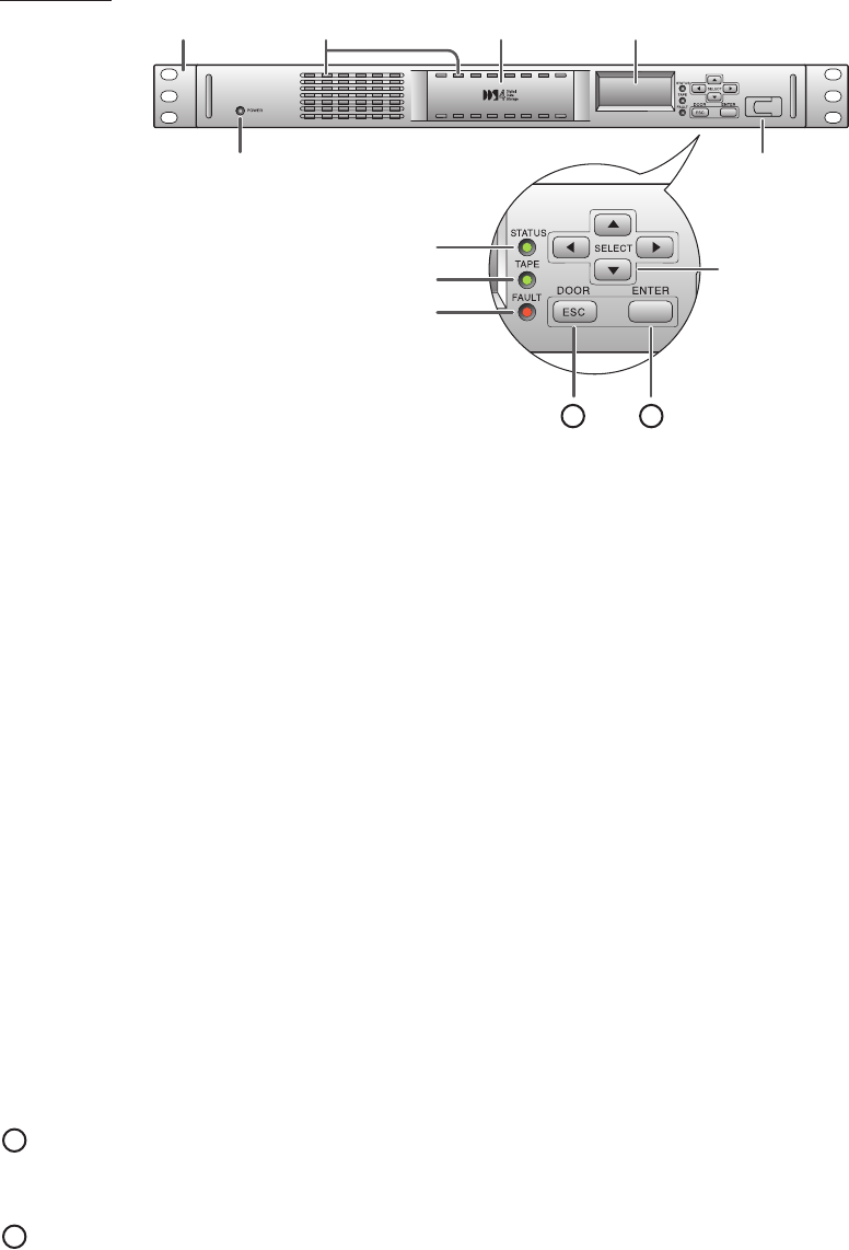
Front View
➀➁➂➃
➄➅
➆
➇
➈
➉
11 12
➀ Rack Mount Plate
For mounting to the rack
➁ Air Flow Hole ( for absorption )
Not be blocked or covered to protect this Library from overheating
➂ Cartridge Insertion Portion ( Door )
Trough hole for setting/ ejecting cartridge tape to/from the Library
➃ LCD Display
Displays the Garage/ Cartridge-tape and the Library operating status,
and Menu mode screen. This has a backlight function.
➄ Power LED
Lights up "Green" when the Library power is ON
➅ Testing Connector
Use for repair/ modification ( Not use generally )
➆ Drive Status LED
Lights up "Green" while accessing to the drive
➇ Tape Status LED
Lights up "Green" while setting a tape in the drive
➈ Fault LED
Lights up "Red" when any system error occurred ( For error detail, see the LCD display)
➉ Cursor Key Button
Press to select garage or cartridge tape ( Operation mode )
Press to select menu item ( Menu mode )
11 ESC/DOOR Button
Press to cancel a execution ( escape the interrupted status ), return to the previous
screen ( Menu mode ), or close the front door.
12 ENTER Button
Press to input any data/ text, execute the command item or set the selected item.
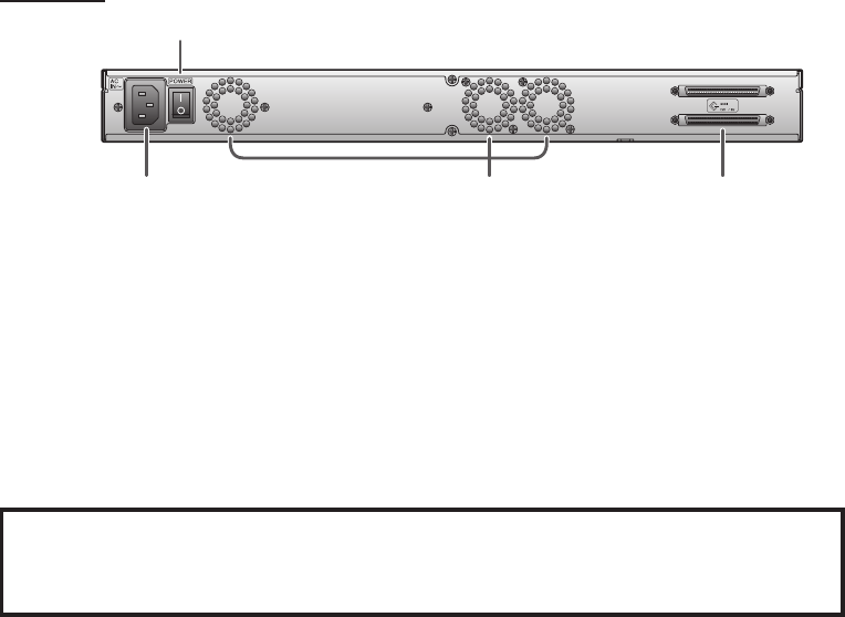
Rear View
➀ Power On/Off Switch
➁ Power Connector
Connect the attached power cable
➂ Fan / Air Flow Hole ( for release )
Not be blocked or covered to protect this Library from overheating
➃ SCSI Interface Connector
Connect the SCSI interface cable ( 68-pin half pitch type )
– If this Library is a terminal device on the SCSI bus, connect the proper terminator
to the other (vacant) connector.
➀
➁➂➃
CAUTION :
When wiring SCSI interface cable under the floor with this product
in the computer room, SURELY use the cable (DP-1, DP-1P, DP-2, DP-2P
or CL2 type) conformed to the Wiring Under the Floor.
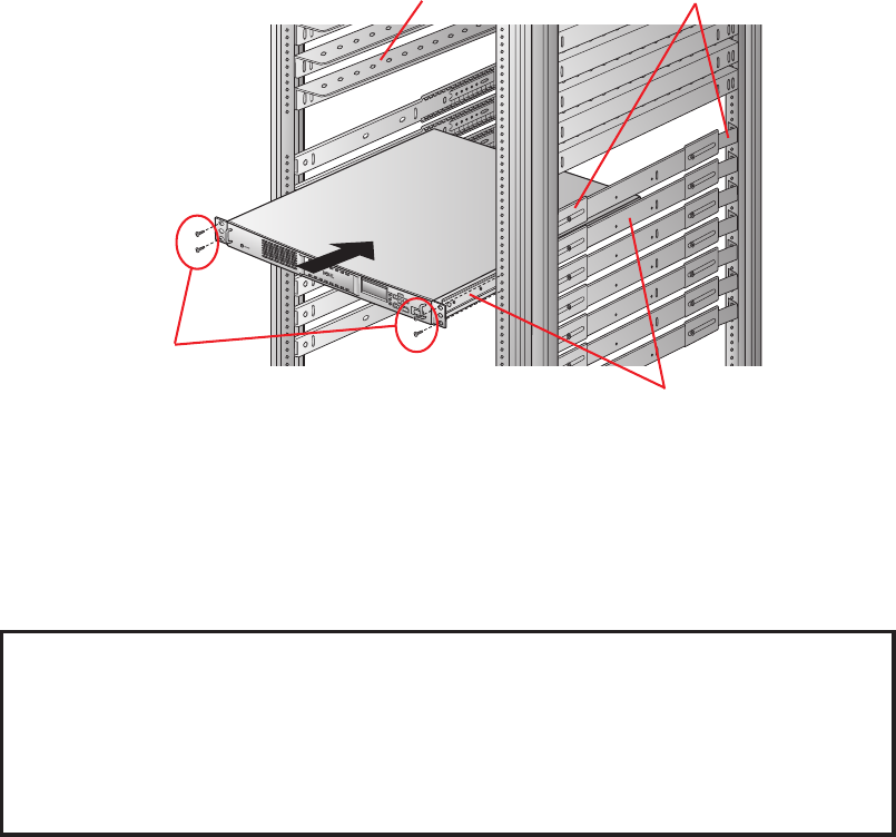
RACK MOUNTING
1) If you need the Rail (Rail-Bracket) or Angle for mounting to your rack, attach the suitable
ones for the Rack / Library to them.
– For details of installing the Rail (Rail-Bracket) or Angle, refer to each manual for them.
2) Gently slide the Library into the vacant rack part, and secure it with mounting screws
as below figure.
Angle Rail-Bracket
Rack Mounting
Screw Rail
Note :
The above equipments ( Angle/ Rail/ Rail-Bracket/ Screw ) are NOT included
with this product.
Please use the screw for mounting rail to the Library unit that its inner length into the
Library is less than 4 mm.
CAUTION :
•The operating ambient temperature of the rack mounting equipment should be
always lower than 40 °C.
•Not be blocked or covered the Air Flow Hole.
•Surely mount to horizontal direction.
•Use the power supply that has enough capacity.
•Connect the attached power cable (grounding-type plug) to a grounding type
power outlet.
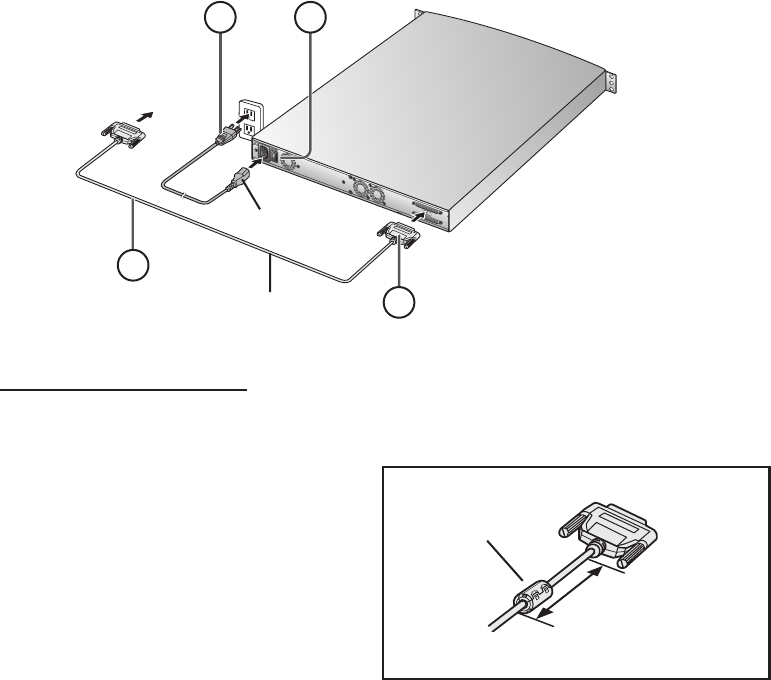
CONNECTING
43
2
1
Please connect the power and SCSI interface cable to the rear of the Library as follows.
Before you begin the below connecting steps, make sure that the host PC and the
library Power switch is OFF. ( Recommended the host PC power cable is unplugged )
➀Connect the SCSI interface cable to the Library.
➁Connect the other end of SCSI interface cable to the host PC's SCSI connector.
➂Connect the attached power cable to the Library and AC outlet.
➃Switch the Library power ON.
When switch the Library power ON, this Library scans the tape In/Out
of all the garages (slots). Please wait for a moment of the slot tape scanning ( until
"READY" is appeared on the LCD ).
➄Set up SCSI ID number with key-buttons and LCD display in Menu mode.
If the default setting is incorrect for your system, please set up according to the system.
( Set up to the vacant ID No. )
➅ – When your OS is “ Solaris® ” –
Set up OS mode number( ‘02’ = “ Solaris® ”OS using number ) with key-buttons and
LCD display in Menu mode.
➆ Turn your host PC power ON.
AC Outlet
Host PC's
SCSI connector
DDS Backup Library
Power Cable
( Attached )
SCSI Interface Cable
( Not attached )
Note:
The connecting sockets are keyed.
If Daisy Chain Connection
If connect other SCSI device to the other SCSI connector on the Library (SCSI daisy Chain
connection), follow the below procedure for EMC (= Electro-Magnetic Compatibility).
Less than
100 mm length
Library side
Other
device side
Ferrite-Core
Note :
These SCSI interface cable and Ferrite-
Core are NOT attached with this product.
Please connect the recommended SCSI
interface cable mounted the Ferrite-Core
to the other SCSI device side
as the right figure.