Panasonic of North America 8GL-PAN802154 OEM Wireless Network Module User Manual
Panasonic Corporation of North America OEM Wireless Network Module
User manual

LR/WPAN PAN802154HAR Application Notes
Doc Number: Rev A3 1
ZB-01 LR-WPAN Module
P/N PAN802154____
Application Notes
Rev Author/Editor Issue Reason Date Release
Approval
A Fox / Nguyen Initial release / Revise 3-22-2005 RBNguyen
A1 Trueman Revise 3-29-2005 RBNguyen
A2 Cardenas Connector Nomenclature Change.
(Use Rev.A1 for earlier Engineering
Samples with Rev. 5 or earlier
artwork)
7-06-2005 RBNguyen
A3 Cardenas Add FCC restrictions and mechanical
drawing
9-22-05

LR/WPAN PAN802154HAR Application Notes
Doc Number: Rev A3 2
Table of content
1 INTRODUCTION …….…………………………………………………………………………… 3
1.1 Regulatory information................................................................................................................................ 3
1.2 Abbreviations and Acronyms ...................................................................................................................... 3
2 LR/WPAN PAN802154HAR FEATURES, AND COMPONENT DESCRIPTION ............... 5
2.1 PAN802154 Image, Component Layout and Block Diagram ................................................................... 6
2.2 Component and Descriptions....................................................................................................................... 7
2.2.1 J3: General Purpose Header.................................................................................................................... 7
2.2.2 J2: Serial Port Header ............................................................................................................................. 7
2.2.3 J4: Power/GND Header .......................................................................................................................... 9
2.2.4 J1: BDM Programming header/Debugger .............................................................................................. 9
2.2.5 SW1: General Purpose Switch.............................................................................................................. 10
2.2.6 D1: LED ............................................................................................................................................... 10
2.2.7 U1: MCU .............................................................................................................................................. 10
2.2.8 U3: RF IC ............................................................................................................................................. 10
2.3 Mechanical Dimensions.............................................................................................................................. 10
3 APPLICABLE SW COMPONENTS .................................................................................. 12
3.1 SW Architecture ......................................................................................................................................... 12
3.1.1 Different Possible Applications with Available Software Components ............................................... 12
3.2 Bootloader ................................................................................................................................................... 12
3.3 Required SW Tools..................................................................................................................................... 13
3.4 Freescale™ ZigBee Development Platform.............................................................................................. 13
3.5 Special mapping for the PAN802154 Module in Metrowerks Code Warrior Development Tool. ...... 13
3.5.1 Compiling with a Z-Stack Project ........................................................................................................ 14
3.5.2 Compiling without using the Z-Stack................................................................................................... 14
3.6 Differences between the Panasonic PAN802154 and the Freescale SARD Development Board ......... 15
3.6.1 Switch................................................................................................................................................... 15
3.6.2 LED ...................................................................................................................................................... 15
3.6.3 RS-232 Interface................................................................................................................................... 16
3.6.4 Editing SARD Header File for the Panasonic Module ......................................................................... 16
3.7 How to load a SW program into the Panasonic Module ......................................................................... 20
4 FREQUENTLY ASKED QUESTIONS .............................................................................. 24
5 REFERENCE DOCUMENTS ............................................................................................ 27
APPENDIX 1 FCC AND CANADA CERTIFICATIONS.......................................................... 30
Instruction to the user............................................................................................................................................ 30
Integration in OEM products: VERY IMPORTANT! ....................................................................................... 30
APPENDIX 2 ORDERING INFORMATION ............................................................................ 32

LR/WPAN PAN802154HAR Application Notes
Doc Number: Rev A3 3
1 INTRODUCTION
The purpose of this document is to present a method for designing products using the Panasonic Low
Rate / Low Power Wireless Area Network Communication Module Part Number PAN802154HAR00 and
familiarize engineers with application details.
A Frequently Asked Questions (FAQ’s) section is also provided for engineering quick references.
Panasonic ZB-01 LR/WPAN PAN802154HAR Module
Panasonic’s LR/WPAN PAN802154 Module is a Low Rate / Low Power communication device based
upon the Freescale™ ZigBee Sensor Application Reference Design (SARD) development platform. It
operates in the ISM 2.4 GHz band, and is fully compliant with the IEEE 802.15.4 standard. The
PAN802154 is ready to be downloaded with Freescale’s 802.15.4 PHY/ MAC layer and ZigBee protocol
layer.
The PAN802154 uses the Freescale’s 802.15.4 transceiver (MC13193), micro controller (GT60) and is
licensed to use all released Freescale ZigBee Protocol stack layer software. Further, the PAN802154
has an on-board RS-232 interface IC and two on-board printed antennas that are etched on both sides of
the board for optimum RF sensitivity. The whole RF section that encompasses U3 and all passive
components and baluns are shielded to prevent RF leakage and further improve RF performance.
The PAN802154 is tested to fully comply with current FCC requirements for 2.4 GHz ISM band
application. This allows the customer to complete and bring the end product to the market much quicker.
The application profile or program can be developed with in-house SW staff or with any third-party SW
development contractor including Panasonic.
1.1 Regulatory information
Refer to Appendix A for regulatory information
FCC ID: Pending
Canada: Pending
1.2 Abbreviations and Acronyms
MCU Micro-controller Unit
FAQ Frequently Asked Questions
LR/WPAN Low Rate / Low Power Wireless Personal Area Network.
Jx Header Connector Number
SW1 General Purpose Switch 1
BDM Background Debugger Module

LR/WPAN PAN802154HAR Application Notes
Doc Number: Rev A3 4
SARD Sensor Application Reference Design
RFD Reduced Function Device
FFD Full Function Device
MAC Media Access Controller
SMAC Simple Media Access Controller
Z-Stack Freescale ™ ZigBee Protocol Stack
IEEE The Institute of Electrical and Electronics Engineers

LR/WPAN PAN802154HAR Application Notes
Doc Number: Rev A3 5
2 LR/WPAN PAN802154HAR FEATURES, AND COMPONENT
DESCRIPTION
PAN802154 Module is designed with all Hardware on board and downloadable SW to be
configured as a FFD Coordinator / Router or a RFD End Node.
PAN802154 Features
• Fully supports ZigBee™, 802.15.4, or Simple MAC Application
• 2.4 GHz ISM, ZigBee™
• 16 Channels, 5MHz channel spacing, Full Spectrum Encode and Decode (IEEE Standard
802.15.4); up to 250 Kbps bit rate.
• RS-232 port; 2 Analog Inputs selectable to 10bit A/D Converter; and up to 8 Digital I/O ports
on easy to connect header connector
• Background Debug Feature
• 1 Switch and 1 LED for control and monitoring
• Output power: 0dBm typical (1mW)
• RX Sensitivity: -92dBm typical at 1.0% Packet Error Rate.
• Shielded RF Section for improved performance
• On board printed antenna or optional connector for external antenna
• Commercial and Industrial Operating Temperature Range
• Power Supply Range:
2.2VDC to 3.4 VDC without using RS-232 capability
3.0VDC to 3.4 VDC with using RS-232 capability
• DC current:
RX/TX: 35mA typical
Doze: 80uA typical
LR/WPAN PAN802154HAR Application Notes
Doc Number: Rev A3 6
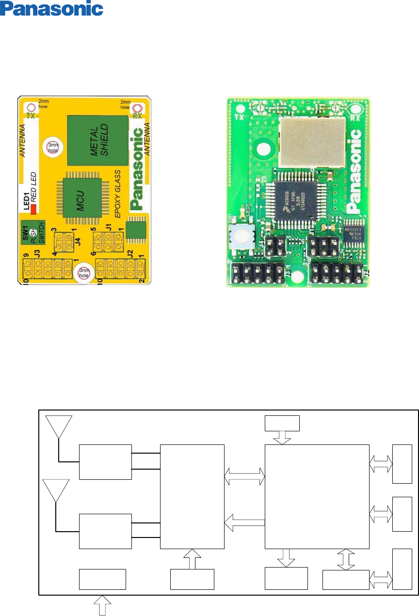
2.1 PAN802154 Image, Component Layout and Block Diagram
All components are on the front side of the PAN802154. No back- side image is shown here
Figure 1: Module connector location Figure 2: Module picture
1) Connectors J1, J2, J3 & J4 straight 2.54" pitch, Contact material Zn
2) Substrate Glass Epoxy t=1.2mm
3) Push switch and red LED used as application required
4) Metal cover to meet FCC rules
5) 3.17mm holes to use 1/8” screw diameter for mounting using non- conductive spacer
Figure 3: Block Diagram
Balun/
LPF
RF+BB
MC13193
32QFP
Balun/
LPF
Flash 60K
RAM 4K
MPU 44QFP
MC9S08GT60CFB
SPI
Standby
16MHz LED1
SW1
RS232C
10 Pins 6 Pins 10 Pins
4 Pins
Voltage
I/O DBM
Serial
Tx
Rx
DC 2.2-3.4V for radio communication
DC 3.0-3.4 for radio communication +RS232 operation
LR/WPAN PAN802154HAR Application Notes
Doc Number: Rev A3 7
2.2 Component and Descriptions
2.2.1 J3: General Purpose Header
Header J3 is intended to be used as a general purpose I/O header. A power and GND pin are also
provided to allow connection to external components.
Use Molex P/N 1544-5810 or 10 pins 0.1” standard female connector as mating receptacle.
Hdr.
Pin # MCU
PORT/PIN
Name
Function Remarks
J3-1 PTA7
J3-2 PTA6
J3-3 PTA5
J3-4 PTA4
J3-5 PTA0
J3-6 PTA1
General purpose digital I/O
J3-1 through J3-4 Can wake MCU from
stop 3 or wait mode. They can detect
falling/rising edges and low/high levels
when keyboard interrupt is enabled
Pins J3-5 and J3-6 can detect falling edges
or low levels when keyboard interrupt is
enabled.
J3-7 VCC Digital Power Pin To provide external power to PAN802154 or
vice versa.
J3-8 GND GND
J3-9 PTB0
J3-10 PTB1
Analog input or general
purpose digital I/O
Connected to MCU Analog-to-digital 10 bit
A/D converter, channels 0 and 1
Table 1: J3 Pin out
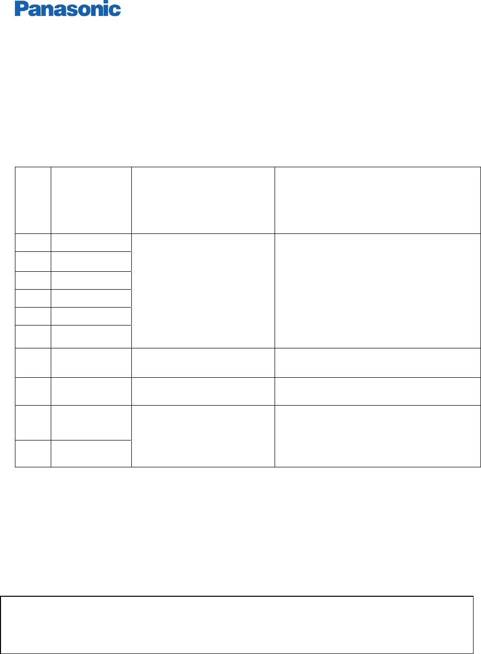
2.2.2 J2: Serial Port Header
Header J2 is a serial port header for connection to a PC’s serial port. The header contains an RS-232
level TX line, an RX line, and GND.
Use Molex P/N 1544-5810 or 10 pins 0.1” standard female connector as mating receptacle.
It is important to note that although the MCU and the Transceiver radio can work as low as 2.4
VDC, proper operation for RS-232 requires VCC to be greater than 3.0 volts DC.
LR/WPAN PAN802154HAR Application Notes
Doc Number: Rev A3 8
Table 2: J2 Pin out
Figure 4: Serial interface cable from PAN802154 to Computer RS232
Hdr.
Pin # MODEL
WITH
RS232
MODEL
WITHOUT
RS232
RS-232
PIN NAME
Function Remarks
J2-1 NC PTE0/TXD1 - Digital port for
control or serial
port
MCU’s Serial Com
Interface data transmit
J2-2 NC PTE1/RSD1 - Digital port for
control or serial
port
MCU’s Serial Com
Interface data receive
J2-3 RS232_TX NC RS232_TX Transmit line
for serial port
RS-232 level transmit
signal
J2-4 NC NC - NC
J2-5 RS232_RX NC RS232_RX Receive line for
serial port
RS-232 level receive
signal
J2-6 NC NC - NC
J2-7 NC PTC6 - Digital port for
control
Shutdown control for
RS232 tranceiver
J2-8 NC NC - NC
J2-9 GND GND GND Ground
J2-10 NC VCC - NC
0.1" pitch female 10 Pin socket connector
ASC10G-ND or ASN10A-ND
RS232-TX
RS232-RX
GND
GND
1
2345
6789
9 pins D-Subminiature female connector
AFS09G-ND or AFL09K-ND
1
2
3
4
5
6
7
8
9
10
LR/WPAN PAN802154HAR Application Notes
Doc Number: Rev A3 9
2.2.3 J4: Power/GND Header
Header J4 is the power connector for the PAN802154.
Use Molex P/N 1544-5804 or 4 pins 0.1” (2.54mm) standard female connector as mating receptacle.
Hdr.
Pin # PIN NAME
Function Remark
J4-1 GND Ground
J4-2 VCC VCC Module’s Power supply Refer to
specification for operating voltage
J4-3 GND Ground
J4-4
AD_REF Analog-to-digital converter
reference voltage
All analog signals are measured with
respect to this reference voltage
Table 3: J4 Pin out
2.2.4 J1: BDM Programming header/Debugger
Header J1 provides the connection for the Flash programmer and software debugger.
Use Molex P/N 1544-5806 or 6 pins 0.1” (2.54mm) standard female connector as mating receptacle.
Hdr.
Pin # PIN NAME
Function Remarks
J1-1 PTG0/BKG0 Serial Programming Line or
General Purpose I/O
This line controls the loading of new
program code to the MCU. Pin has 4.7K
pull-up. After code is loaded, acts as digital
I/O.
J1-2 GND Ground
J1-3 - N/C
J1-4 /RESET Reset to MCU Active-low reset
J1-5 - N/C
J1-6 VCC Provides power to BDM
debugger module
Table 4: J1 Pin out
LR/WPAN PAN802154HAR Application Notes
Doc Number: Rev A3 10
2.2.5 SW1: General Purpose Switch
SW1 is a general-purpose switch that connects to PTA2. Pressing the switch will pull the signal to GND.
The internal pull-up for PTA2 must be enabled to use this switch in an application.
2.2.6 D1: LED
The LED is connected to PTD0 through a 330-ohm resistor. Setting the PTD0 pin to an output and
setting the value high will turn on the LED. Setting the pin low will turn off the LED.
2.2.7 U1: MCU
U4 is the Micro-Controller Unit -- Freescale part number: MC9S08GT60CFB. It has an 8-bit
microprocessor, 60K byte Flash, 4 K byte RAM, and a 10 bit A/D converter. In addition to its capability to
process the 802.15.4 PHY/MAC and protocol stack, it still has plenty of processing power left to run
simple, normal sensor/actuator applications.
2.2.8 U3: RF IC
U3 is the radio frequency transceiver –Freescale part number: MC13193. This transceiver together with
U1 MCU forms a fully compliant IEE 802.15.4 IEEE Standard radio. The whole RF section that
encompasses U3, all passive components and baluns are shielded to improve overall RF performance.
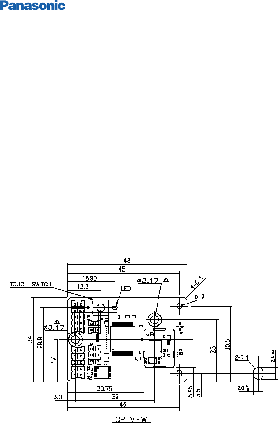
2.3 Mechanical Dimensions

LR/WPAN PAN802154HAR Application Notes
Doc Number: Rev A3 11
Figure 5: Mechanical drawing
Mating receptacles for board to board connection
4 Pin Connector: Molex P/N 15-44-5804 as mating connector
6 Pin Connector: Molex P/N 1544-5806 as mating connector
10 Pin Connector: Molex P/N 1544-5810 as mating connector

LR/WPAN PAN802154HAR Application Notes
Doc Number: Rev A3 12
3 APPLICABLE SW COMPONENTS
3.1 SW Architecture
Application Program
Freescale™ ZigBee
PROTOCOL STACK
802.15.4 MAC LAYER
PHY LAYER
Diagram Three: PAN802154 SW Architecture
The bottom 3 layers may be downloaded from Freescale™ ‘s website. Only the Application Program or
Profile will need to be generated by the system developer. There are many reference code examples
available from the Freescale™ website.
Depending on the application, the following Freescale™ SW components may be appropriate:
a) Freescale Embedded Bootloader
b) 802.15.4 PHY/MAC
c) ZigBee Protocol Stack
All of the SW above is downloadable from Freescale website; http://www.freescale.com/ZigBee
3.1.1 Different Possible Applications with Available Software Components
The PAN802154 can function with a variety of Freescale-provided software such as:
a.) SMAC (Simple MAC)
b.) 802.15.4 MAC
c.) ZigBee Protocol Stack
Depending on the desired application complexity, the user may choose one of the above SW
environments SMAC is the simplest, followed by the 802.15.4 MAC. Using the ZigBee protocol stack on
top of the 802.15.4 MAC will be the most complex and allows the end product to meet the ZigBee
Alliance standard.
The system user may elect to not use the Freescale provided ZigBee protocol stack and develop a
system application based on the 802.15.4 standard protocol only. This could happen with legacy
applications that need not be interoperable with the ZigBee community devices.
For even simpler system, the user can even ignore the 802.15.4 MAC and just use the SMAC (Simple
MAC), and develop the application program on top of this MAC.
3.2 Bootloader
The PAN802154 comes with only the Bootloader loaded.
LR/WPAN PAN802154HAR Application Notes
Doc Number: Rev A3 13
For engineering samples, please start the SW application development process by erasing all
contents of the flash (60K bytes) prior to loading any SW components.
3.3 Required SW Tools
You will need the following SW tools to develop an application program/profile.
1) Metrowerks Codewarrior Development Studio for HC(S)08 64K C Compiler. Part Number CWS-H08-
C64K-CX. (http://store.metrowerks.com)
2) Freescale™ ZigBee Development tool --- This tool is available from Freescale
3) BDM MULTILINK Flash Programming tool ( Software and hardware). This is available from PEMicro
in USB or parallel port presentation. (www.pemicro.com)
3.4 Freescale™ ZigBee Development Platform
Freescale™ Semiconductor has created several hardware and software development platforms. The Z-
Stack and 802.15.4 MAC were created to work with all of these specific hardware platforms.
If you are already familiar with one of the Freescale™ Development Platforms, using the Panasonic
Module in your system is very easy as The Panasonic PAN802154 is most closely resembles the SARD.
3.5 Special mapping for the PAN802154 Module in Metrowerks Code Warrior Development
Tool.
Panasonic PAN802154 uses the Freescale GT60 MCU (U1) in conjunction with the MC13193
Transceiver (U3) --- the correct MCU part number must be chosen for the specific device function role
for the compiler to generate the correct object code.
There are basically 3 function devices
a) End Device – (Reduced Function Device - RFD)
b) Router Device – (Full Function Device - FFD)
c) Device Coordinator – (Full Function Device - FFD)
Note that only FFD can communicate with any device. RFD can only communicate with
FFD, and not with another RFD.
Metrowerks Code Warrior Development Studio for HC (S) 08 64K Compiler is the compiler. Libraries and
source code projects provided by Freescale™ are compatible with this compiler. The compiler may be
found on the Freescale™’s website at www.freescale.com. The 64K-compiler upgrade is needed to
compile the full ZigBee stack.
LR/WPAN PAN802154HAR Application Notes
Doc Number: Rev A3 14
3.5.1 Compiling with a Z-Stack Project
For compiling with the Z-Stack, the compile flag TARGET_DIG536_2 needs to be added to the
Codewarrior project settings. There are two ways to do this. If you are working in a Z-Stack project,
simply select the GT60 DIG536 target in whichever project is to be compiled (see figure 2 below).
Figure 6: Using pre-defined project setting
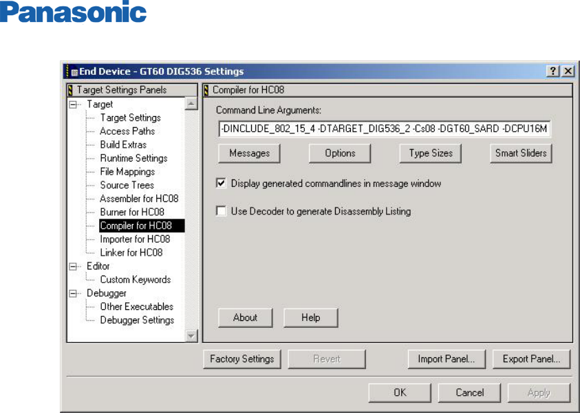
3.5.2 Compiling without using the Z-Stack
Without using the Z-Stack, one can manually set the project settings compile flag. This is possible by
clicking on the project setting button in CodeWarrior and selecting ‘Compiler for HC08’. You can then
manually add compile flags to the command line arguments (see figure 3 below). Entering ‘ –
DTARGET_DIG536_2’ accomplishes this mapping.
LR/WPAN PAN802154HAR Application Notes
Doc Number: Rev A3 15
Figure 7: Manually setting compile
3.6 Differences between the Panasonic PAN802154 and the Freescale SARD Development
Board
If the User is already familiar with the Freescale SARD Development Board – then using the PAN802154
is very easy.
The Panasonic PAN802154 has a different hardware configuration than the SARD board, improved RF
performance, one switch versus four; one LED versus four; the RS-232 interface has an additional
control connection to conserve power.
3.6.1 Switch
Setting the target settings to the SARD affects all the pin-outs for the PAN802154. The SARD board
layout includes four user switches labeled SW1, SW2, SW3, and SW4. However, the PAN802154 has
only one and it is labeled SW1. Nothing needs to be done in software due to this difference in layouts.
This should be kept in mind when attempting to run Freescale demonstration applications that uses
these switches.
The port used is the same for SW1 (PTD0).
3.6.2 LED
The SARD board had four LEDs as well, however, only one is used on the PAN802154. The port used
for the LED (LED1) is PTD0, which is the same as LED1 on the SARD board. This should be kept in
mind when developing software for the PAN802154s.

LR/WPAN PAN802154HAR Application Notes
Doc Number: Rev A3 16
3.6.3 RS-232 Interface
The MCU has the capability to connect to two separate serial ports, however, the Panasonic PAN802154
has only one header for a serial port connection. This header is connected to SCI1 (serial
communications interface 1).
The RS-232 IC used in the PAN802154 allows for a low-power sleep mode. Control of this sleep mode
is done through a MCU I/O pin, PTC6. To force the RS-232 IC into a sleep mode, set pin PTC6 low.
When the RS-232 IC is in sleep mode, the RS-232 will not operate. To wake the RS-232 IC up, set
PTC6 high .
3.6.4 Editing SARD Header File for the Panasonic Module
Following sections show how to modify the SARD Header into the Panasonic PAN802154 Header File
because of the difference in quantity of LEDs, Switches (or Push Buttons) as indicated in paragraphs
above.
3.6.4.1 Header File Modification for SMAC applications
For SMAC applications, the LED and SW definitions are in the application header file.
To enable these applications to run on the PAN802154, just delete the lines from the header file that
defines LED2, LED3 and LED4. Also, delete the lines that indicate PB1, PB2, and PB3 (Note the
nomenclature difference – Panasonic uses SW; where as the SARD use PB). Also, be sure not to use
these definitions in any of the ZigBee applications. The example given below is from wireless_uart.h,
which is at SMAC_DIRECTORY\apps\Wireless Uart\Sources directory.
Example is below.
#if defined(MC13192SARD)
#define LED1 PTDD_PTDD0
#define LED1DIR PTDDD_PTDDD0
#define LED2 PTDD_PTDD1 <-- Delete
#define LED2DIR PTDDD_PTDDD1 <-- Delete
#define LED3 PTDD_PTDD3 <-- Delete
#define LED3DIR PTDDD_PTDDD3 <-- Delete
#define LED4 PTDD_PTDD4 <-- Delete
#define LED4DIR PTDDD_PTDDD4 <-- Delete
#define LEDPORT PTDD
#define PB0 PTAD_PTAD2
#define PB0PU PTAPE_PTAPE2
#define PB0DIR PTADD_PTADD2
#define PB1 PTAD_PTAD3 <-- Delete
#define PB1PU PTAPE_PTAPE3 <-- Delete

LR/WPAN PAN802154HAR Application Notes
Doc Number: Rev A3 17
#define PB1DIR PTADD_PTADD3 <-- Delete
#define PB2 PTAD_PTAD4 <-- Delete
#define PB2PU PTAPE_PTAPE4 <-- Delete
#define PB2DIR PTADD_PTADD4 <-- Delete
#define PB3 PTAD_PTAD5 <-- Delete
#define PB3PU PTAPE_PTAPE5 <-- Delete
#define PB3DIR PTADD_PTADD5 <-- Delete
#define PB0IE KBI1PE_KBI1PE2
#define PB1IE KBI1PE_KBI1PE3 <-- Delete
#define PB2IE KBI1PE_KBI1PE4 <-- Delete
#define PB3IE KBI1PE_KBI1PE5 <-- Delete
#define PRESSED 0
#endif
3.6.4.2 Header File Modification for 802.15.4 MAC applications
For 802.15.4 MAC applications, the Target.h header file needs to be edited in order to remove the
configuration for the SW2, SW3, SW4 and LED2, LED3, LED4, as well as any Macros that exist for
Switches and LED’s that do not exist on the PAN802154. This file is in the 802.15.4 Directory under
Src/GHDR/Target.h.
Also, no application should call any LED macros.
Port A and D Setup
Original code looks as follows
#define mSETUP_PORT_A PTAPE = 0x3C;\ <-- Change to 0x04
PTADD = 0x00;
#define mSETUP_PORT_D PTDPE = 0x00;\
PTDDD = (0x01 | 0x02| 0x08 | 0x10); <-- only keep 0x01
After editing, the code will be as shown below
#define mSETUP_PORT_A PTAPE = 0x04;\
PTADD = 0x00;
#define mSETUP_PORT_D PTDPE = 0x00;\
PTDDD = (0x01);
LED Setup
Original code looks as follows
#define LED1_PIN (1<<0)
#define LED2_PIN (1<<1) <- Delete

LR/WPAN PAN802154HAR Application Notes
Doc Number: Rev A3 18
#define LED3_PIN (1<<3) <- Delete
#define LED4_PIN (1<<4) <- Delete
#define LED1ON PTDD &= 0xFE;
#define LED1OFF PTDD |= 0x01;
#define LED1TOGGLE PTDD ^= 0x01;
#define LED2ON PTDD &= 0xFD; <- Delete
#define LED2OFF PTDD |= 0x02; <- Delete
#define LED2TOGGLE PTDD ^= 0x02; <- Delete
#define LED3ON PTDD &= 0xF7; <- Delete
#define LED3OFF PTDD |= 0x08; <- Delete
#define LED3TOGGLE PTDD ^= 0x08; <- Delete
#define LED4ON PTDD &= 0xEF; <- Delete
#define LED4OFF PTDD |= 0x10; <- Delete
#define LED4TOGGLE PTDD ^= 0x10; <- Delete
After editing the header file for the PAN802154, the code will be as follows
#define LED1_PIN (1<<0)
#define LED1OFF PTDD &= 0xFE;
#define LED1ON PTDD |= 0x01;
#define LED1TOGGLE PTDD ^= 0x01;
Switch Setup
Original code
#define mSWITCH1_MASK 0x04
#define mSWITCH2_MASK 0x08 <- Delete
#define mSWITCH3_MASK 0x10 <- Delete
#define mSWITCH4_MASK 0x20 <- Delete
#define mSWITCH_MASK 0x3C <- Change to 0x04
After Editing for the module
#define mSWITCH1_MASK 0x04
#define mSWITCH_MASK 0x04
3.6.4.3 Header file Modification for Z-Stack Applications
If compiling for a Z-Stack application, the header file OnBoard.h needs to be edited. This file is located
at:
F8W\FS-1.0-1.0.0-RC2\Z-Stack\ZMain.
The Z-Stack uses this header file within the application framework, so the LED and SWITCH definitions
cannot simply be deleted or the project will not build. Instead, they can just be set to 0 so that no action
is taken if they attempt to be used.
It is important to note that the Z-Stack demo applications use the switches for various uses. But since
some switches are not available on the PAN802154, these switch Macros must be set to 0 (deleting the
LED macros will cause the Z-Stack to not compile).

LR/WPAN PAN802154HAR Application Notes
Doc Number: Rev A3 19
LED Macros
Original code
#define LED_NONE 0x00
#define LED1 0x01
#define LED2 0x02 <-- Set to 0
#define LED3 0x04 <-- Set to 0
#define LED4 0x08 <-- Set to 0
#define LED_ALL (LED1 | LED2 | LED3 | LED4) <-- Delete LED2,3,4
After Editing for the module, the code shall be
#define LED_NONE 0x00
#define LED1 0x01
#define LED2 0x00
#define LED3 0x00
#define LED4 0x00
#define LED_ALL (LED1)
Switch Macros
Original code
#elif defined( GT60_SARD ) || defined ( GT60_EVB )
#define EVAL_SW_MASK 0x3C <-- Change to 0x04
#define EVAL_SW4 0x20
#define EVAL_SW3 0x10
#define EVAL_SW2 0x08
#define EVAL_SW1 0x04
After editing for the module
#elif defined( GT60_SARD ) || defined ( GT60_EVB )
#define EVAL_SW_MASK 0x04
#define EVAL_SW4 0x20
#define EVAL_SW3 0x10
#define EVAL_SW2 0x08
#define EVAL_SW1 0x04
LR/WPAN PAN802154HAR Application Notes
Doc Number: Rev A3 20
3.7 How to load a SW program into the Panasonic Module
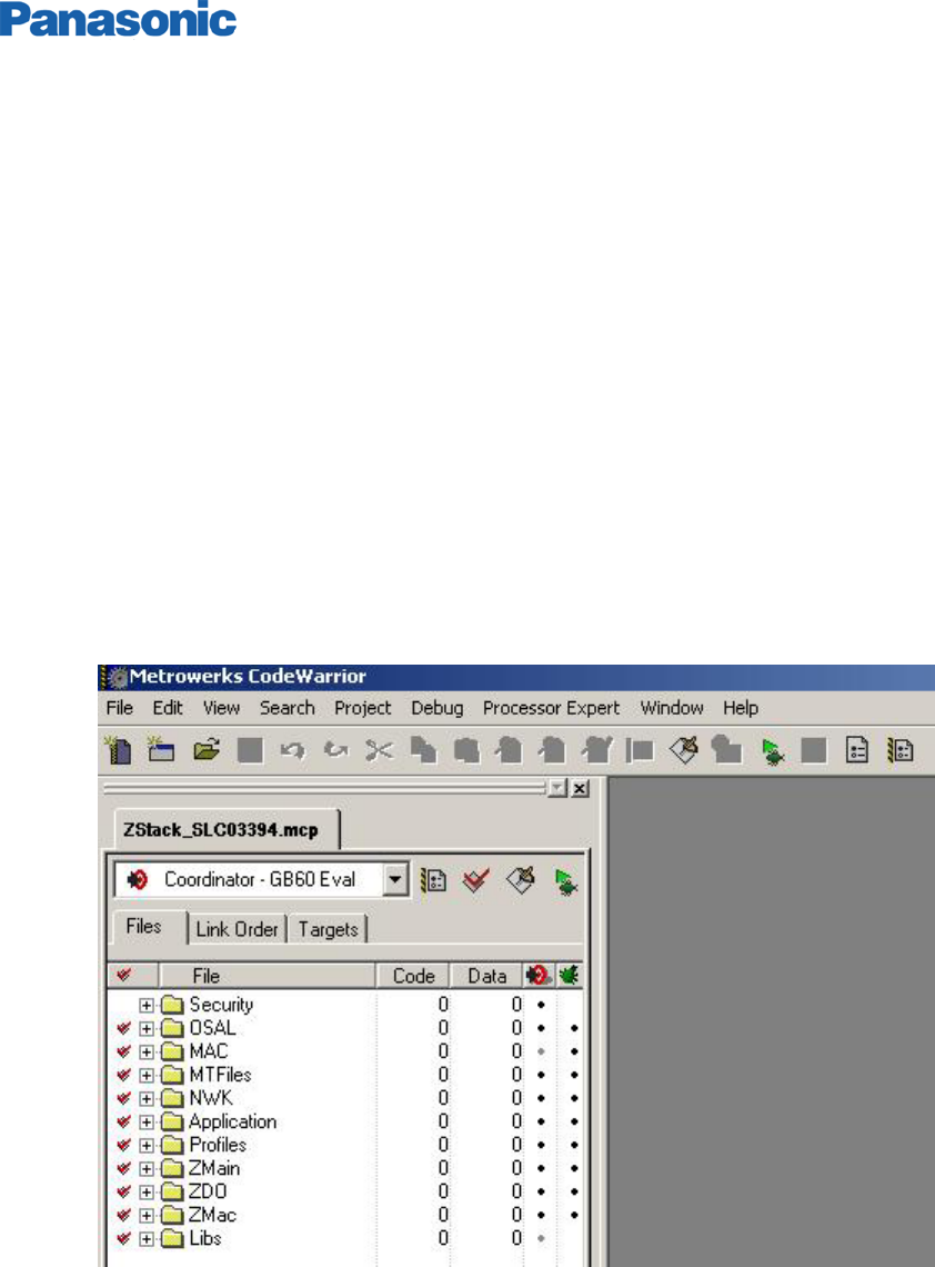
The following example shows a step-by-step for loading software build for a Z-Stack application to the
PAN802154.
1. Open Metrowerks Codewarrior Development Studio for HC(S) 08.
2. Open one of the example projects in the Z-Stack directory. This example uses the Home lighting
Controls project. In Codewarrior IDE, select File->Open. The location is
C:\F8W\FS-1.0-1.0.0-RC2\Z-Stack\Projects\HomeLighting\SLC03394\MC13192\Zstack_SLC03394.mcp
The project will open and your screen will appear as below.
Figure 8: Z-Stack application
LR/WPAN PAN802154HAR Application Notes
Doc Number: Rev A3 21
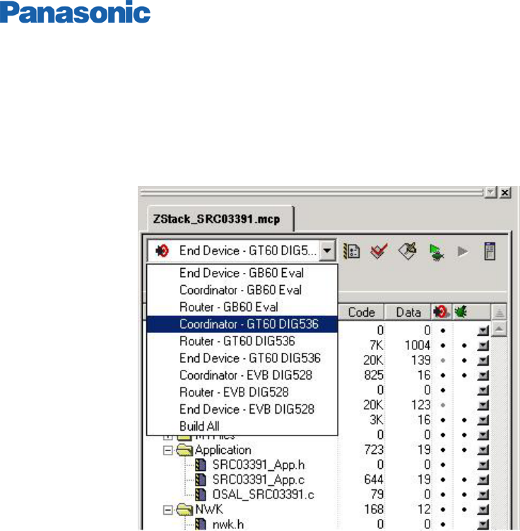
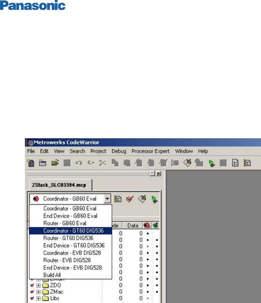
3. The project needs to be mapped to the correct hardware configuration. This is accomplished by
clicking the down-facing arrow and selecting the target as XXX – GT60 DIG536. This sets up the
compile options (XXX is Coordinator, Router, or End Device, depending on the application that is to
be loaded into the PAN802154).
Figure 9: Mapping the hardware configuration
LR/WPAN PAN802154HAR Application Notes
Doc Number: Rev A3 22
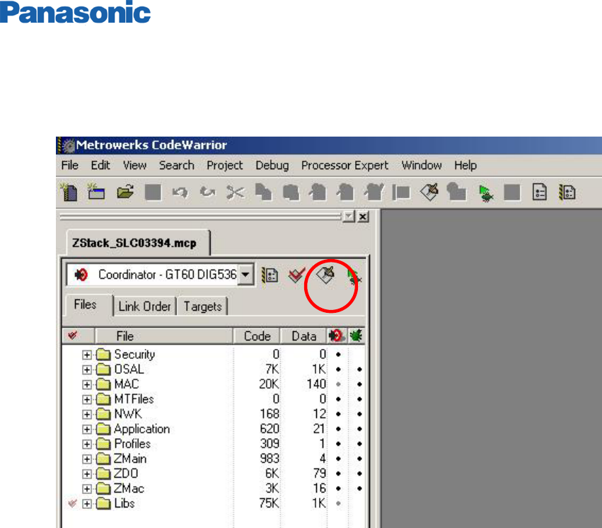
4. To load the software, connect the BDM-Multilink 6-pin connector to J5 header on the PAN802154.
Click the green button circled below. The code will compile and download the program to the Module.
Figure 10: Loading the application

LR/WPAN PAN802154HAR Application Notes
Doc Number: Rev A3 23
Page intentionally blank.

LR/WPAN PAN802154HAR Application Notes
Doc Number: Rev A3 24
4 FREQUENTLY ASKED QUESTIONS
Q1: What is the LR/WPAN PAN802154HAR00 Panasonic Module?
A: The PAN802154 is a low rate / low power communication radio module adapting from the Freescale
SARD platform. It is fully 802.15.4 compatible with a Freescale™ ZigBee Protocol stack. It has 1 Push-
button switch, 1 LED, 1 RS-232 port, general-purpose header with 6 digital I/O and 2 analog inputs for
A/D conversion (The 2 analog inputs can be used as Digital I/Os). The PAN802154 also has on board
antenna for cost reduction and meets FCC requirements.
Q2: Does my end product have to get FCC certification and ZigBee certification if we use the
Module?
A: Although the PAN802154 is already tested at Panasonic factory for FCC compliance, the end product
will need to be certified as an end consumer item. Ditto for the ZigBee compliance for your specific end
product Application SW.
Q3: Does the ZigBee stack come with the PAN802154? What form does it come in and what is
included?
A: Yes. The Freescale ZigBee stack itself is provided in object code form, however, an example for
application framework and operating system environment is provided in source-code form. The Stack is
available for download from the Freescale website.
Q4: Is there any development tool for using the Z-Stack?
A: The Z-Stack has development tools that assist in application development and deployment. The Z-
stack tools are available for the following development purposes.
a.) Z-Tool for debugs
b.) Configurator for embedded application setup and source code generation.
c.) Profile-builder for building custom ZigBee profiles
d.) Z-Network for providing a graphical representation of a ZigBee Network.
Q5: Same question as above, but for 802.15.4 MAC
A: 802.15.4 MAC is separated into a PHY and a MAC layer. The PHY layer is provided in source-code
form. Pre-built libraries are provided for all Freescale’s development platforms. The MAC is provided in
library form only.
Q6: Does the PAN802154 correspond to any Freescale Development Platform?
A: The PAN802154 adapts the Freescale™’s SARD development platform. The part number for the
SARD board is DIG536-2, and the design can be found on Freescale’s website. The PAN802154
contains only 1 push-button switch and 1 LED, whereas the SARD board has 4 switches and 4 LEDs.
The PAN802154 has an extra signal goes to the RS-232 chip to enable sleep-mode on the RS-232 chip
to save power.

LR/WPAN PAN802154HAR Application Notes
Doc Number: Rev A3 25
Q7: What compiler is used for ZigBee application development?
A: Metrowerks CodeWarrior Development Studio for HC (S) 08 64K Compiler is the compiler. Libraries
and source code projects provided by Freescale™ are compatible with this compiler. The compiler can
be found on Freescale’s website at www.freescale.com. The 64K-compiler upgrade is needed to
compile the full ZigBee stack.
Q8: Do the PAN802154s come with any software loaded onto them?
A: The modules will come loaded with a Bootloader (Engineering samples may contain sample
applications). The Bootloader allows software to be downloaded to the PAN802154 through the serial
port. A command-line interface to this Bootloader is provided by Freescale™ and available for
download.
Q9: Is any special hardware needed to load code to the ZigBee modules?
A: Loading of software can be done through a standard serial port connected to a PC and Freescale’s
serial Bootloader application (Freescale’s specific bootloader.s19 file must be downloaded into module’s
flash before this feature can be used). File format for this loading is Motorola s-record (S19) files. If
more control of software loading and flash erasing is desired; a hardware debugger is available from
www.pemicro.com. Part number is BDM-MULTILINK (uses pc’s parallel port) or USB-ML-12 (uses pc’s
USB port).
Q10: What programming language is used for application programming?
A: Standard C is used to write the embedded applications. Some assembly can be used for speed-
critical sections of code.
Q11: What are the power supply requirements?
A: For wireless communication without using the RS-232, the power supply voltage must be between
2.2 and 3.4 volts DC. With RS-232 operation, the supply voltage must be between 3 and 3.4 volts DC.
Q12: What distance can be expected for wireless communication?
A: Line of sight communication between two modules can be as far as 200 meters. With a few stucco
walls, in a building environment the distance between the two modules could be as good as 30 meters.
Q13: Describe the general-purpose I/O header?
A: The PAN802154 contains a 10-pin general purpose I/O header. This header provides up to 8 digital
I/O. Two of the digital I/O pins can also be used as analog inputs to the analog-to-digital converter in the
MCU. Power and Ground are also provided on this header.
Q14: What is the baud rate for the serial port?
A: The baud-rate is programmable.

LR/WPAN PAN802154HAR Application Notes
Doc Number: Rev A3 26
Q15: What kind of battery life is expected?
A: The battery-life for the PAN802154 is entirely dependent on the application. In applications that only
require only a few transmissions per hour, batteries may last several years, alternately, in applications
that require continuous transmissions batteries may only last a few months.
Q16: How big is the Freescale ZigBee stack?
A: Version 1.0 stack size is dependent on the device type. Below is a simple table for current sizes of
ZigBee stack + 802.15.4 MAC, including security. More code-size reduction efforts are taking place.
Coordinator: 54,714 bytes
Router: 51,705 bytes
Node: 43,053 bytes
Note that with this code size, for the GT60 MCU a fair amount of ROM (equals to 60Kbytes minus the
amount used above for each type) is still available from the Flash to store the application program. The
above code size is expected to be substantially smaller in future releases.
Q17: Can I use the PAN802154 with another protocol stack other than the Freescale ZigBee
stack?
A: Yes. As long as the replaceable stack is compatible with the Freescale provided 802.15.4 PHY /
MAC; and it is also compiled for the GT60 MCU and MC13193 Transceiver.
Q18: Can I use the PAN802154 with the SMAC only for my simple legacy system?
A: Yes. For simple legacy application program, you can just use the SMAC only.
LR/WPAN PAN802154HAR Application Notes
Doc Number: Rev A3 27
5 REFERENCE DOCUMENTS
Panasonic LR/WPAN802154HAR00 Specification
From Freescale - Documents below are downloadable from Freescale™ website
http://www.freescale.com/ZigBee
SMAC
Doc. Title: Simple Media Access Controller User's Guide
Doc. Num: SMACRM/D
802.15.4 MAC
Doc. Title: 802.15.4 MAC/PHY Software Reference Manual
Doc. Num: 802154MPSRM/D
Doc. Title: 802.15.4 MAC/PHY Software Users Guide
Doc. Num: 802154MPSUG/D
Z-Stack
High-Level Design
Doc. Title: Z-Stack Application Framework (AF) Application Programming Interface
Doc. Num: F8W-2003-0010
Doc. Title: Z-Stack Application Framework (AF) Application Programming Interface
Doc. Num: F8W-2003-0025
Doc. Title: Z-Stack Compile Flag Definitions
Doc. Num: F8W-2004-0013
Doc. Title: Z-Stack Device Object (ZDO) Application Programming Interface
Doc. Num: F8W-2004-0025

LR/WPAN PAN802154HAR Application Notes
Doc Number: Rev A3 28
Doc. Title: ZigBee Device Object Programmer's Guide
Doc. Num: F8W-2004-0008
Doc. Title: Z-Stack Network (NWK) Application Programming Interface
Doc. Num: F8W-2003-0008
Doc. Title: ZigBee Dimmer Load Controller (03395) Device Description Programmer's
Guide
Doc. Num: F8W-2003-0034
Doc. Title: ZigBee Dimmer Remote Control (03392) Device Description Programmer's
Guide
Doc. Num: F8W-2003-0033
Doc. Title: ZigBee Generic Application Programmer's Guide
Doc. Num: F8W-2003-0032
Doc. Title: ZigBee Light Sensor Monochromatic (02080) Device Description Programmer's
Guide
Doc. Num: F8W-2003-0029
Doc. Title: ZigBee Occupancy Sensor (03393) Device Description Programmer's Guide
Doc. Num: F8W-2003-0035
Doc. Title: ZigBee Serial Application Programmer's Guide
Doc. Num: F8W-2003-0018
Doc. Title: ZigBee Switch Load Controller (03394) Device Description Programmer's Guide
Doc. Num: F8W-2003-0028

LR/WPAN PAN802154HAR Application Notes
Doc Number: Rev A3 29
Doc. Title: ZigBee Switch Remote Control (03391) Device Description Programmer's Guide
Doc. Num: F8W-2003-0027
Integration Test
Doc. Title: Z-Stack Integration Test Plan
Doc. Num: F8W-2003-0021
OS Abstraction Layer
Doc. Title: Z-Stack OS Abstraction Application Programming Interface
Doc. Num: F8W-2003-0002
Serial Port Interface
Doc. Title: Z-Stack/Z-Test Serial Port Interface
Doc. Num: F8W-2003-0001
LR/WPAN PAN802154HAR Application Notes
Doc Number: Rev A3 30
APPENDIX 1 FCC AND CANADA CERTIFICATIONS
Instruction to the user
47 C.F.R. Sec. 15.21
This equipment has been tested and found to comply with the limits for a Class B digital device,
pursuant to part 15 of the FCC Rules. These limits are designed to provide reasonable protection
against harmful interference in a residential installation. This equipment generates uses and can
radiate radio frequency energy and, if not installed and used in accordance with the instructions, may
cause harmful interference to radio communications. However, there is no guarantee that
interference will not occur in a particular installation. If this equipment does cause harmful
interference to radio or television reception, which can be determined by turning the equipment off
and on, the user is encouraged to try to correct the interference by one or more of the following
measures:
• Reorient or relocate the receiving antenna.
• Increase the separation between the equipment and receiver.
• Connect the equipment into an outlet on a circuit different from that to which the receiver is
connected.
• Consult the dealer or an experienced radio/TV technician for help.
47 C.F.R. Sec.15.105(b)
This equipment complies with FCC radiation exposure limits set forth for an uncontrolled
environment. The antenna(s) used for this equipment must be installed to provide a separation
distance of at least 8 inches (20cm) from all persons.
Integration in OEM products: VERY IMPORTANT!
The PAN802154 module (ZB-01) has been certified as a transmitter module by the FCC rule 15 and
Industry Canada. It can be integrated into OEM products without obtaining subsequent and separate
FCC approvals according to the FCC public notice DA 00-1407 June 26, 2000.
The OEM must satisfy the following requirements to comply with the FCC regulations:
1) The OEM integrator will not use the Panasonic FCC ID or Canada grant code with out a previous
contract agreement on which the exact application and scope of the final product will be
declared.
2) If the PAN802154 is integrated in another enclosure and the FCC label is not visible, then the
device into which the module is installed must also display a label such as the Figure11.
LR/WPAN PAN802154HAR Application Notes
Doc Number: Rev A3 31
This device Contain a transmitter module: PAN802154 HAR00
IC: Pending FCC ID: Pending
* The enclosed device complies with Part 15 of the FCC Rules. Operation is subject to the
following two conditions: (1) This device may not cause harmful interference, and (2) This device
must accept any interference received, including interference that may cause undesired operation.
Figure 11: Label to be attached to the outside of the OEM product
3) The users manual should include a statement such as the one in figure 2:
Figure 12: Caution statement to be included in OEM users manual
4) Any modification to this product may violate the rules of Federal Communications Commission
and make the operation of the product unlawful. If the OEM integrates the module into their final
product, where the final product utilizes non-approved antennas or is classified as a portable
device per FCC Section 2.1093, the OEM is responsible for obtaining a separate authorization on
the final product.
5) The module has been designed and tested for battery operation. The OEM is responsible for
conducted emissions compliance and has to demonstrate that it pass the conducted limits if the
final product include or make provisions for the use of battery eliminators or AC adapters or if it
gets power indirectly from AC lines.
6) OEM is responsible for the compliance of the FCC regulations for Unintentional radiators section
15.107 and 15.109 on their final product.
CAUTION STATEMENT!
47 C.F.R. Sec. 15.21
This equipment has been tested and found to comply with the limits for a Class B digital device, pursuant to
part 15 of the FCC Rules. These limits are designed to provide reasonable protection against harmful
interference in a residential installation. This equipment generates uses and can radiate radio frequency
energy and, if not installed and used in accordance with the instructions, may cause harmful interference to
radio communications. However, there is no guarantee that interference will not occur in a particular
installation. If this equipment does cause harmful interference to radio or television reception, which can be
determined by turning the equipment off and on, the user is encouraged to try to correct the interference by
one or more of the following measures:
• Reorient or relocate the receiving antenna.
• Increase the separation between the equipment and receiver.
• Connect the equipment into an outlet on a circuit different from that to which the receiver is connected.
• Consult the dealer or an experienced radio/TV technician for help.

LR/WPAN PAN802154HAR Application Notes
Doc Number: Rev A3 32
APPENDIX 2 ORDERING INFORMATION
RF module()
example only
P A N 8 0 2 1 5 4 H A R 0 0
(1) (2) (3) (4)
(1) Product Code
(2) Product Series
(3) Product Type
H: Header Connector
A: On Board Antenna
R: RS-232C interface
0: Commercial Temperature Range; I: Industrial Temperature Range.
(4) Design version number