Panasonic of North America 96NBL-C20 2.4 GHz WIRELESS CAMERA User Manual BLC20A GS
Panasonic Corporation of North America 2.4 GHz WIRELESS CAMERA BLC20A GS
USERS MANUAL
Getting Started
Network Camera
Model No. BL-C20A
Please read the Important Information manual before using.
This Getting Started explains how to connect, set up and mount the
camera. See the Operating Instructions on the Setup CD-ROM for
details about the camera's features.
•
If you cannot complete the setup, see the Troubleshooting manual
on the Setup CD-ROM
.
This product is a wireless Network Camera. Using a PC and wireless router, it allows you to view images in a residence or from distant places over the
Internet.
2005 Panasonic Communications Co., Ltd. All Rights Reserved.
PQQX14937ZA
KK0905YT0
Wireless Type
Indoor Use Only
Trademarks
•
Adobe, Acrobat and Reader are either registered trademarks or trademarks of Adobe Systems Incorporated in the United States and/or other countries.
•
Microsoft, Windows and ActiveX are either registered trademarks or trademarks of Microsoft Corporation in the United States and/or other countries.
•
Screen shots reprinted with permission from Microsoft Corporation.
•
All other trademarks identified herein are the property of their respective owners.
•
This software is based in part on the work of the Independent JPEG Group.
Abbreviations
•
UPnP is the abbreviation for "Universal Plug and Play".
•
"Network Camera" is called "Camera" in this manual.
•
"Setup CD-ROM" is called "CD-ROM" in this manual.
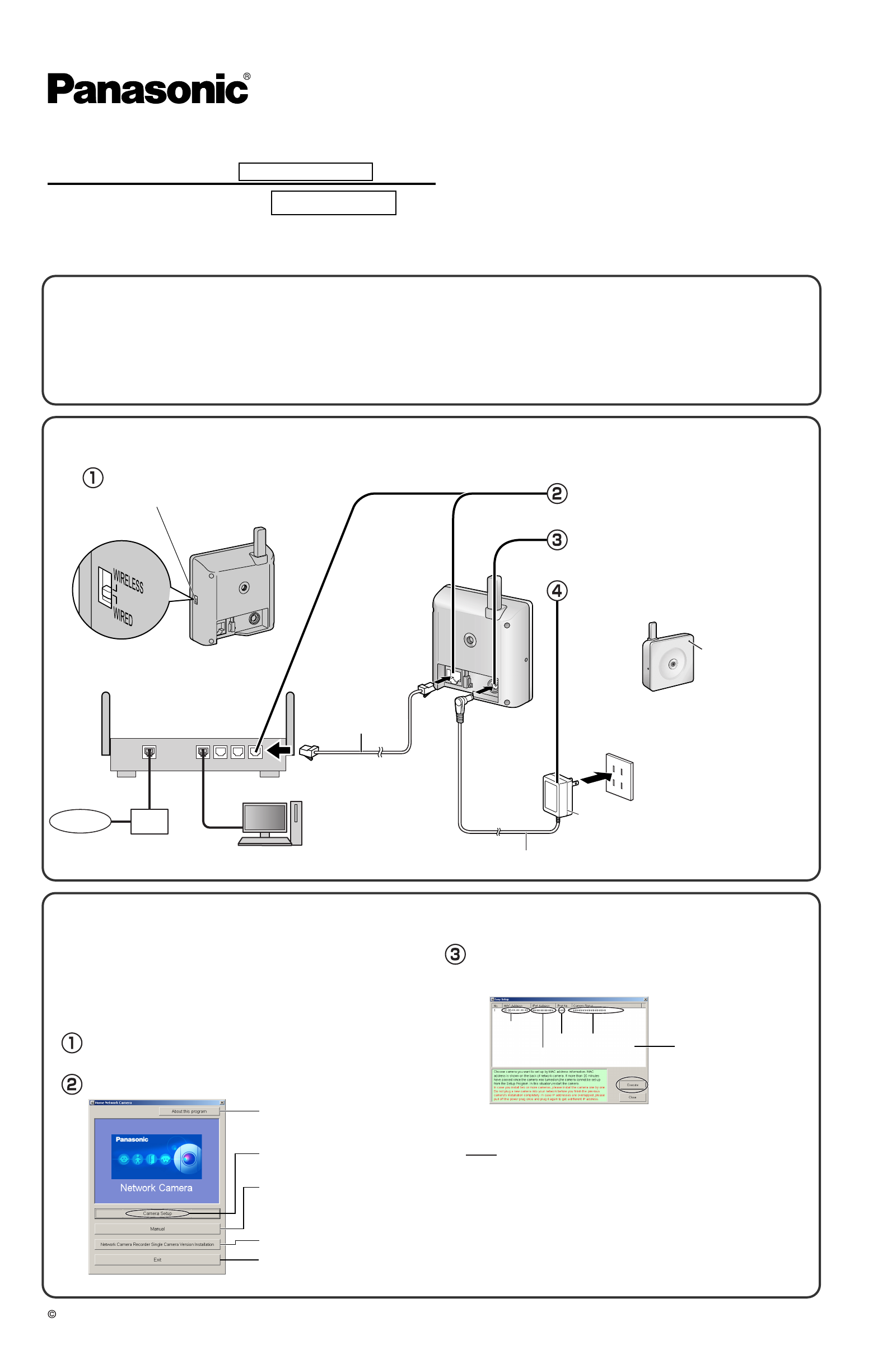
1. Connect the camera to your router.
•
The PC should be connected to the router, and to the Internet, in advance.
Router
(Customer-provided)
WAN 4321
LAN
•
Confirm that the indicator lights green after about
30 seconds.
•
If the indicator does not light green, see page 19
and 20 of Troubleshooting on the CD-ROM.
•
The camera may become warm. This is not a
malfunction.
The indicator
lights green.
Ethernet cable
(Straight Cat5 cable,
Customer-provided)
AC Cord
AC Adaptor
Modem
Internet
PC
(For setup and display [Customer-provided])
Connect the Ethernet cable (customer-
provided) to the camera and the router.
Plug the AC adaptor into the outlet.
Connect the AC adaptor cord to the DC In
jack.
Confirm that the switch on the side of
the camera is set to WIRED.
<Side>
Switch
Insert the CD-ROM into the CD-ROM drive of the PC.
(If the Network Camera Setup window is not displayed automatically,
double-click the "Setup.exe" file on the CD-ROM.)
Select the camera to set up and click [Execute].
•
This program searches for the cameras that are connected to the router
and displays their MAC Addresses, IP addresses and Port Numbers.
Displays the camera manuals.
If your PC does not have Adobe®
Acrobat® Reader®, install it from
the Adobe Reader website.
Closes the Setup Program.
•
The MAC Address on the rear side (see page 9 of the Operating Instructions
on the CD-ROM) of the camera shows which camera you select on the
Camera List window.
Displays version information
about this program.
2. Set up the camera.
Sets up the camera.
Click [Camera Setup].
Important
•
To avoid any possible problems, temporarily disable any firewall
or antivirus software.
•
This procedure explains installation of the camera on the same
network as your PC.
•
Before proceeding, close your web browser.
Installs Network Camera Recorder
Single Camera Version.
•
If a Windows Security Alert is displayed, click [Unblock].
• If the indicator does not light green, check the connection (see page 7 of the
Operating Instructions on the CD-ROM, or page 3 and 4 of the
Troubleshooting).
• If more than 20 minutes have passed since the camera was turned on, the
camera cannot be set up from the Setup Program. In this situation, disconnect
the AC adaptor from the outlet, and reconnect it again.
• The Setup Program may not list any cameras due to your firewall or antivirus
software settings on your PC. If you cannot disable your firewall or antivirus
software, you can set up the camera by entering the camera MAC address. The
camera's MAC address can be found on the label affixed to the rear of each
camera. See page 9 of the Operating Instructions on the CD-ROM for details.
Notes
Camera
List window
Camera
Status
Port
No.
MAC
Address
IP
Address
NetCam
When the Single Camera page is displayed, setup
is complete.
Click [Next] to set up the Internet access to the cam-
era and go to step in "To Set Up Internet Access
to the Camera".
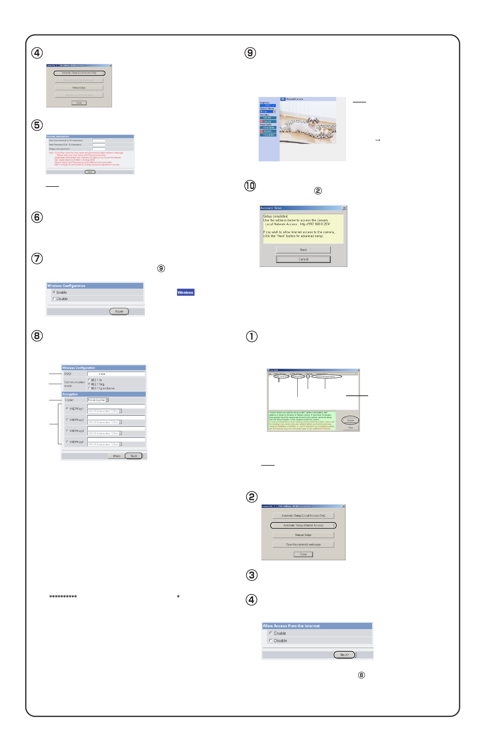
Enter the user name and password, and click [Save].
The Enter Network Password window is displayed.
Enter the user name and password that were set, and
click [OK].
Make a note of the user name and password.
To ensure that the most current image
is displayed, Internet Explorer should
be configured as follows. This will not
have a negative effect on normal use.
1. While viewing any website, click
[Tools] [Internet Options].
2. In the section "Temporary Internet
Files", click [Settings] and check
[Every visit to the page].
•
If the Security Warning window is displayed when installing ActiveX®
Controls, click [Yes].
•
To install ActiveX Controls on Microsoft® Windows® XP Service Pack
2, see "Security Warning window on Microsoft Windows XP Service
Pack 2" on page 3.
•
Click [Cancel] and go to the last page if
you will mount the camera.
•
If you set wireless configuration, confirm
the wireless LAN setup seeing page 3.
•
This program searches for the cameras that are connected to the router
and displays their MAC Addresses, IP addresses and Port Numbers.
•
The MAC Address on the rear side (see page 9 of the Operating
Instructions on the CD-ROM.) of the camera shows which camera you
select on the camera list window.
If more than 20 minutes have passed since the camera was turned on, the
camera cannot be set up from the Setup Program. In this situation, restart the
camera.
Note
Note
1
2
3
4
Set the Wireless Configuration according to the wireless
settings of the router and click [Next>].
•
For more information about wireless setting, see
http://panasonic.co.jp/pcc/products/en/netwkcam/
1. Set the SSID.
Set the name of the wireless network.
2. Select the Communication mode.
These are IEEE Communication modes. Select the same
Communication mode as
that of the router to which the camera is connected.
802.11b (IEEE802.11b) :
Only the 802.11b wireless router can be connected.
802.11b/g (IEEE802.11g) : Either the 802.11b or 802.11g router can be
connected.
802.11g exclusive (IEEE802.11g) : Only the 802.11g router can be connected.
3. Select encrypting or not encrypting.
Selecting WEP can encrypt data within the wireless LAN.
WEP: Encrypting (setting WEP) makes it difficult for unauthorized users to read
data within the wireless LAN, even if they can receive it. To encrypt data, set
the same encryption key to every terminal within the wireless LAN. There are
3 kinds of encryption key: 64 bit, 128 bit and 152 bit. Security level of
encryption increases in order of length as follows: 64 bit, 128 bit and 152 bit.
No encryption: select when not using encryption.
4. Set the WEPKey1–4.
Selecting [WEP] at Cipher enables you to set WEPKey1–4. One or all of the four
keys can be set. Check the key number set to the router, and set the same key as at
the router.
:The entered WEPKey will be displayed as " "s regardless of the key
type selected.
<Example>
HEX, 10 characters 64 bit : 012345abcd
HEX, 26 characters 128 bit : 0123456789abcdef012345abcd
HEX, 32 characters 152 bit : 0123456789abcdef0123456789abcdef
ASCII 5 characters 64 bit : 012yz
ASCII 13 characters 128 bit : 0123456uvwxyz
ASCII 16 characters 152 bit : 0123456789uvwxyz
•
Wireless Configuration can also
be set at on the Setup
Page. (See page 37 of the
Operating Instructions on the
CD-ROM.)
Click [Automatic Setup (Local Access Only)].
Click [Automatic Setup (Internet Access)].
The Enter Network Password window is displayed. Enter the
user name and password that were set, and click [OK].
Select the camera on the camera list to set up the
Internet access and click [Execute].
To Set Up Internet Access to the
Camera
When using a router that supports UPnPTM, check [Enable].
When using a router that does not support UPnPTM, check
[Disable]. Then click [Next>].
•
Check if your router supports UPnPTM referring to the router's manual.
•
If you select [Disable], skip to step on the next page.
Note
Camera
List window
Camera
Status
Port
No.
MAC
Address
IP
Address
To set Wireless Configuration, check [Enable] and click [Next>].
•
When [Disable] is selected, skip to step .
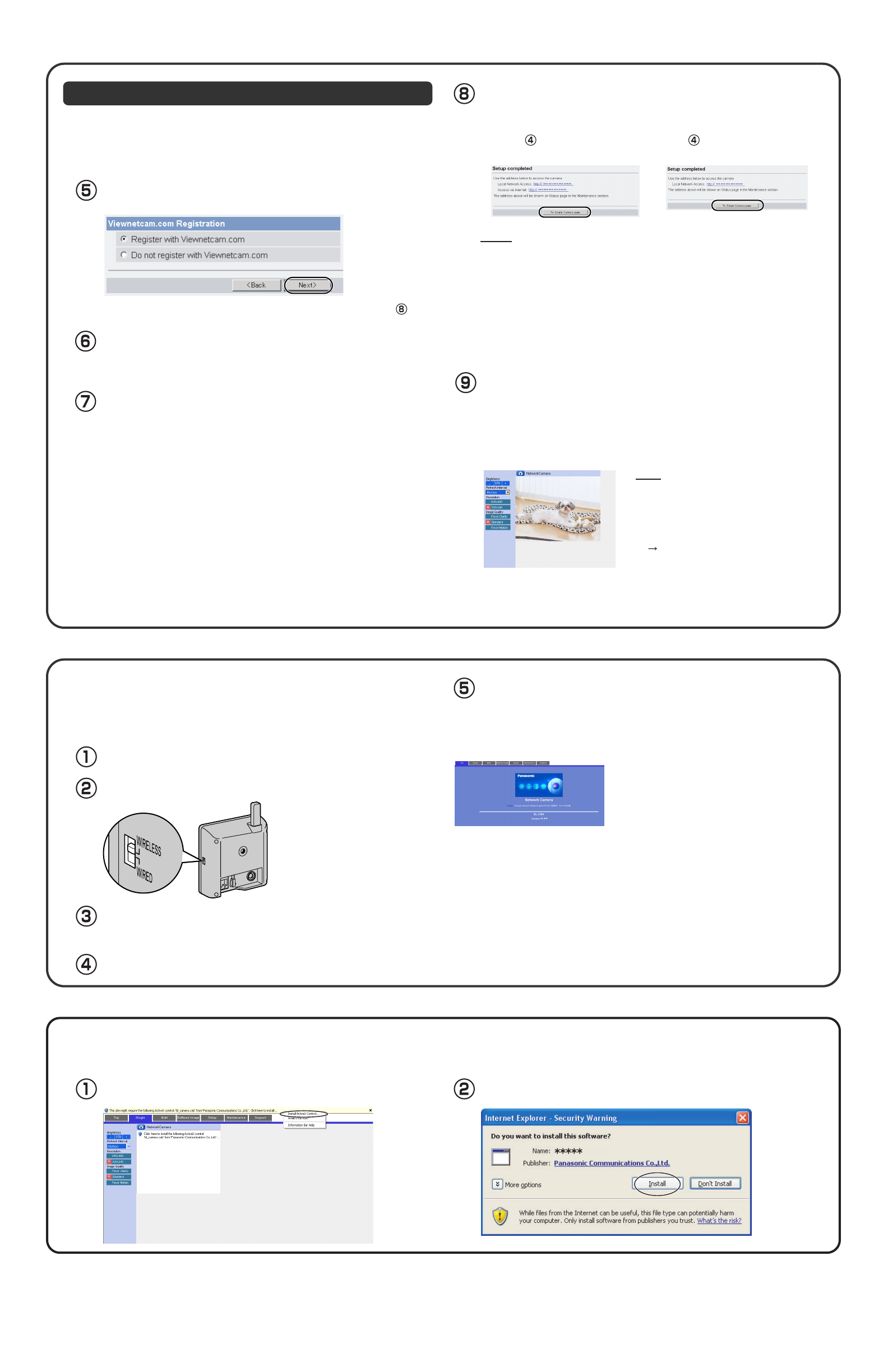
Registration with the "Viewnetcam.com FREE DDNS service"
To ensure that the most current image is
displayed, Internet Explorer should be
configured as follows. This will not have a
negative effect on normal use.
1. While viewing any website, click [Tools]
[Internet Options].
2. In the section "Temporary Internet
Files", click [Settings] and check [Every
visit to the page].
•
If a Security Warning window is displayed when installing ActiveX
Controls, click [Yes].
•
To install ActiveX Controls on Microsoft Windows XP Service Pack
2, see "Security Warning window on Microsoft Windows XP Service
Pack 2" below.
•
If you set wireless configuration, confirm the wireless LAN setup below.
Note
•
When [Enable] was selected
at step in the "To Set Up
Internet Access to the Camera".
•
The port number must be specified at the end of the camera URL.
For example
Using port 80: http://(Cameraname).viewnetcam.com
or http://IP Address
Using any other port: http://(Cameraname).viewnetcam.com:Port Number
or http://IP Address:Port Number
•
The URL for the local network access may be different from the one set up on
the previous page.
•
If you selected [Do not register with Viewnetcam.com], skip to step .
•
When [Disable] was selected at
step in "To Set Up Internet
Access to the Camera".
Set the switch on the side of the camera to WIRELESS.
Start up the web browser on the PC.
After setting each item for the wireless LAN, confirm that the camera works
correctly.
Unplug the Ethernet cable and turn off the power (disconnect
the AC adaptor).
Turn on the power by connecting the AC adaptor to the
outlet.
•The camera switches from wired to wireless.
Enter "http://IP address (or URL):Port No." in the address field
and press [Enter].
(When port number is 80 (default), you do not need to enter port number.)
•
When the following Top Page is displayed, the wireless LAN setup is
successful.
•
If the Top Page was not displayed, the settings
for the camera are not identical with those for the
router. Check the settings by using wired connec-
tion.
If the settings are correct and you use a proxy
server, set the web browser not to access the
proxy server.
If the Top Page is not displayed even after trying
these methods, contact the retailer.
•
It takes about 1 minute for the new settings to be
effective.
•
It is not possible to access the camera simultane-
ously by both wired and wireless connection.
Confirming the Wireless LAN Setup
By registering with the Viewnetcam.com FREE DDNS service, you can
create a personalized web address at which your camera's live video can
always be found on the Internet. For detailed information, access
"http://www.viewnetcam.com".
Security Warning window on Microsoft Windows XP Service Pack 2
To view a video (Motion JPEG), ActiveX Controls must be installed. Follow the steps shown below to install ActiveX Controls.
Click the warning displayed above the tabs, and click [Install
ActiveX Control...]. Click [Install].
When "Setup completed" is displayed, click [To Single
Camera page].
When the Single Camera page is displayed, setup is complete.
Notes
To register with the "Viewnetcam.com FREE DDNS service",
check [Register with Viewnetcam.com] and click [Next>].
The Enter Network Password window is displayed.
Enter the user name and password that were set, and click
[OK].
The "Viewnetcam.com FREE DDNS service" website is
displayed. Follow the displayed instructions for registration.
•
If the message "Failed to configure the router's Port Forwarding by UPnP" is
displayed, your router may not support UPnP
TM
or UPnP
TM
is not enabled.
Enable your router's UPnP
TM
or set Port Forwarding manually following the
router's manual, and try Automatic Setup again. For more information about
setting up a router, refer to the Panasonic Network Camera support web-site
at
http://panasonic.co.jp/pcc/products/en/netwkcam/
•
If the message "Failed to register with Viewnetcam.com." is displayed,
confirm that the router is connected to the Internet.
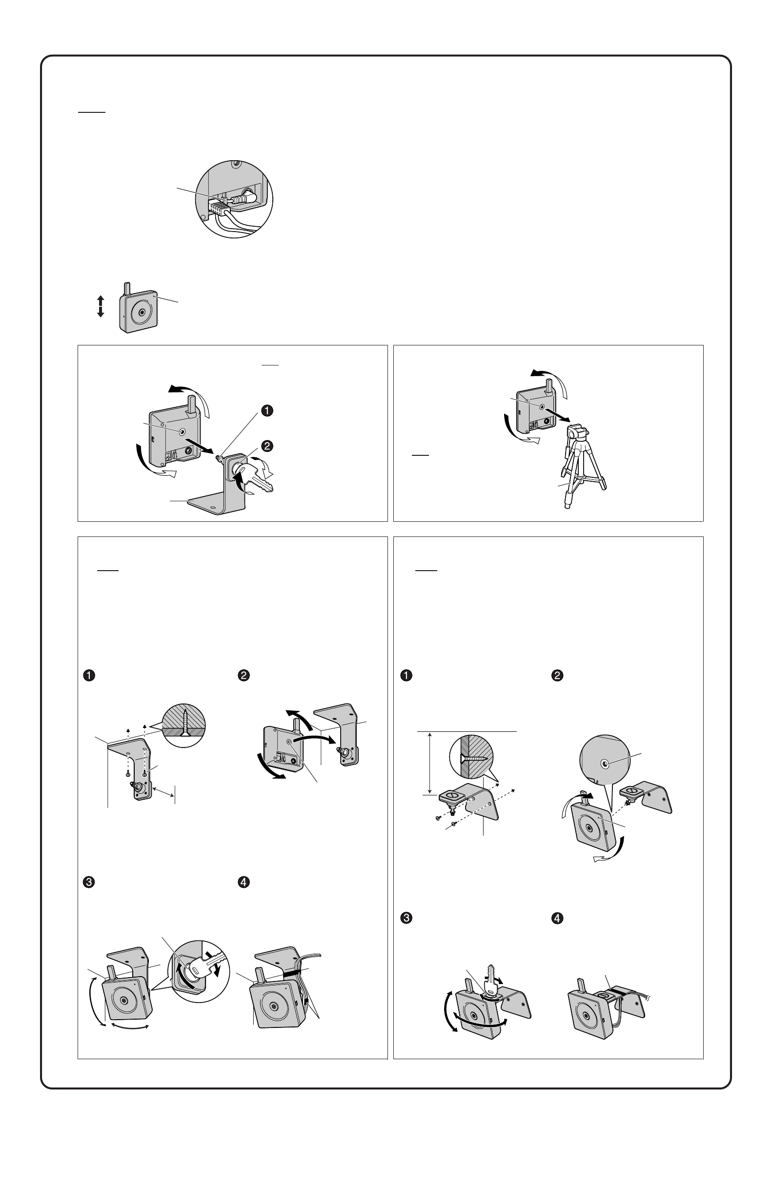
4.
Mount the camera.
The camera can be mounted in the following ways.
•
Do not mount the camera where the sun light directly hits the camera or in outdoor-type housing without a temperature control system. The camera may
malfunction due to high temperature.
•
When you mount the camera, always hook the AC adaptor cord to the hook.
Notes
Hook for
AC adaptor cord
• This product is for indoor use only. Do not use it outdoors.
• The camera may become warm. This is not a malfunction.
• Do not mount the camera upside down, as the image will be displayed upside down.
Make sure the indicator is
always in the upper right
corner.
To p
Bottom
Stand Mount
Stand/Tripod
Mounting Hole
Flexible
Stand
Turn the camera to attach it
to the mounting screw on the
flexible stand.
Loosen the mounting screw
to adjust the angle, then
refasten it again.
• The mounting screw can
be manually adjusted.
Tripod Mount
Stand/Tripod
Mounting Hole
Tripod
Ceiling Mount
• Do not mount the camera upside down, as the image will be displayed upside
down.
• We recommend only mounting the camera using the provided hardware.
Mounting in any other manner may cause the camera to fall, resulting in
personal injury or damage to the camera.
• To reduce the load on the mounting hardware, dress the cables neatly and
secure with tape.
• Disconnect all cables from the camera. Reconnect the cables after mounting
the camera.
•Do not mount the camera on a soft
material. The camera may fall and
be damaged.
•Use appropriate screws for the
material of the ceiling.
•The mounting screw can be
manually adjusted.
Notes
Mount the flexible stand firmly to the
ceiling with the two screws (included).
Turn the camera to firmly attach it
to the flexible stand.
Loosen the mounting screw to adjust
the angle, then refasten it again.
Screw
Allow sufficient space between
the wall and the flexible stand
to turn the mounting screw.
Stand/Tripod
Mounting Hole
Mounting Screw
Tape
(customer-provided)
Wall Mount
• Do not mount the camera upside down, as the image will be displayed upside
down.
• We recommend only mounting the camera using the provided hardware.
Mounting in any other manner may cause the camera to fall, resulting in
personal injury or damage to the camera.
• To reduce the load on the mounting hardware, dress the cables neatly and
secure with tape.
• Disconnect all cables from the camera. Reconnect the cables after mounting
the camera.
Notes
Mount the flexible stand firmly to the
wall with the two screws (included).
Turn the camera to firmly attach it
to the flexible stand.
Screw
Allow sufficient space between the
ceiling and the flexible stand to turn
the mounting screw.
Stand/Tripod
Mounting
Hole
Indicator
•Do not mount the camera on a soft
material. The camera may fall and
be damaged.
•Use appropriate screws for the
material of the wall.
Mounting Screw
Tape
(customer-provided)
Disconnect all cables from the
camera. Reconnect the cables
after mounting the camera.
Note
Do not use a tripod screw with a
thread of 6 mm or more. (This
may damage the Stand/Tripod
mounting hole.)
Note
Connect the AC adaptor cord and
Ethernet cable to the camera and
dress the cables neatly and secure
with tape (customer-provided). Loosen the mounting screw to adjust
the angle, then refasten it again.
•The mounting screw can be
manually adjusted.
Connect the AC adaptor cord and
Ethernet cable to the camera and
dress the cables neatly and secure
with tape (customer-provided).
Important Information
Network Camera
2005 Panasonic Communications Co., Ltd. All Rights Reserved.
PQQX14941ZA KK1105JT0
Model No. BL-C1A
BL-C20A
Wired Type
Indoor Use Only
Wireless Type
IMPORTANT SAFETY INSTRUCTIONS
When using this unit, basic safety precautions should always be
followed to reduce the risk of fire, electric shock, or personal injury.
SAVE THESE INSTRUCTIONS
1. Read and understand all instructions.
2. Keep these instructions.
3. Heed all warnings.
4. Follow all instructions.
5. To clean the camera lens, first remove any dust or dirt from the lens,
then wipe the lens with a cotton swab.
6. Do not block any ventilation openings. Install in accordance with
instructions.
7. Do not install near any heat sources such as radiators, heat registers,
stoves, or other devices (including amplifiers) that produce heat.
8. Protect the AC adaptor cord from being walked on or pinched
particularly at plugs, convenience receptacles, and the point where
they exit from the unit.
9. When you operate the camera, the power outlet should be near the
camera and easily accessible.
10. Only use attachments/accessories (such as stands) specified by the
manufacturer.
11. Do not touch the unit, AC adaptor or AC adaptor cord during lightning
storms.
12. Unplug the unit when unused for long periods of time.
13. Refer all servicing to qualified service personnel. Servicing is required
when the unit has been damaged in any way, such as when the AC
adaptor or AC adaptor cord is damaged, the unit does not operate
normally, or after the unit has been dropped.
14. The camera is intended for indoor use only. Prolonged exposure to
direct sunlight or halogen light may damage the CMOS sensor.
15. [For BL-C20A] Please check local regulations as outdoor use of the
wireless feature is restricted in some countries/areas.
16. Unplug this unit from power outlets if it emits smoke, an abnormal
smell or makes unusual noise. These conditions can cause fire or
electric shock. Confirm that smoke has stopped and contact an
authorized service center.
Trademarks
• Microsoft and Windows are either registered trademarks or trademarks of
Microsoft Corporation in the United States and/or other countries.
• Pentium is a trademark or registered trademark of Intel Corporation or its
subsidiaries in the United States and other countries.
• All other trademarks identified herein are the property of their respective
owners.
• This software is based in part on the work of the Independent JPEG Group.
Abbreviations
• UPnP is the abbreviation for "Universal Plug and Play".
• "Network Camera" is called "Camera" in this Installation.
• "Setup CD-ROM" is called "CD-ROM" in this manual.
This manual is for both BL-C1A (Wired Type) and BL-C20A (Wireless
Type). Available features and operations are different in part
depending on the model. Read this manual carefully and use the
Network Camera properly. (The model no. is indicated on the upper
left of the front of the main unit.) The Network Camera includes the
following 4 manual types.
•Important Information (This manual)
This manual has important information you will need to understand
before installing.
•Getting Started
Getting Started explains the initial configuration and mounting methods
of the Network Camera, to help you to set up the Network Camera
quickly and easily.
•Operating Instructions (Included on the Setup CD-ROM)
Operating Instructions explains the operations, settings, features and
maintenance of the Network Camera.
•Troubleshooting (Included on the Setup CD-ROM)
Troubleshooting provides troubleshooting help.
How to Use This Documentation
FCC and Other Information
This equipment has been tested and found to comply with the limits for a Class B digital device, pursuant to Part 15 of the FCC Rules. These limits are
designed to provide reasonable protection against harmful interference in a residential installation. This equipment generates, uses and can radiate radio
frequency energy and, if not installed and used in accordance with the instructions, may cause harmful interference to radio communications.
However, there is no guarantee that interference will not occur in a particular installation. If this equipment does cause harmful interference to radio or
television reception, which can be determined by turning the equipment off and on, the user is encouraged to try to correct the interference by one or
more of the following measures:
• Reorient or relocate the receiving antenna.
• Increase the separation between the equipment and receiver.
• Connect the equipment into an outlet on a circuit different from that to which the receiver is connected.
• Consult the dealer or an experienced radio/TV technician for help.
[For BL-C1A] This device complies with Part 15 of the FCC Rules. Operation is subject to the following two conditions:
(1) This device may not cause harmful interference, and (2) this device must accept any interference received, including interference that may cause
undesired operation.
[For BL-C20A] Some wireless Cameras operate at frequencies that may cause interference to nearby TVs and VCRs. To minimize or prevent such
interference, the base of the wireless Camera should not be placed near or on top of a TV or VCR. If interference is experienced, move the wireless
Camera further away from the TV or VCR. This will often reduce or eliminate interference. Operating near 2.4 GHz electrical appliances may cause
interference. Move away from the electrical appliances.
Environment:
Do not install the camera where the temperature is less than 0 ˚C (+32 ˚F) or greater than +40 ˚C (+104 ˚F). Allow 10 cm (4 inches) clearance around
the unit for proper ventilation. Avoid excessive smoke, dust, mechanical vibration, shock, or direct sunlight.
Routine care:
Wipe the unit with a soft cloth. Do not use benzine, thinner, or any abrasive powder.
When you leave the unit unused for a long period of time, disconnect the AC adaptor from the outlet.
If you have any problems:
Consult an authorized Panasonic Factory Service Center.
Please read this manual before using, and save this manual for future
reference.
Panasonic Network Camera Website: http://www.panasonic.com/netcam for
customers in the USA or Puerto Rico
Carefully pack your unit, preferably in the original carton.
Attach a letter, detailing the symptom, to the outside of the carton.
Symptom
Send the unit to an authorized servicenter, prepaid and adequately insured.
Do not send your unit to the Panasonic Consumer Electronics Company listed left or to
executive or regional sales offices. These locations do not repair consumer products.
When you ship the product
Panasonic Servicenters are listed in the servicenter directory.
Call 1-800-272-7033 for the location of an authorized servicenter.
This Network Camera is designed for use in the United States of America.
Sale or use of this product in other countries/areas may violate local laws.
For product service
Panasonic Consumer Electronics Company,
Division of Panasonic Corporation of North America
Panasonic Puerto Rico, Inc.
The information in this document is subject to change without notice.
Copyright:
This material is copyrighted by Panasonic Communications Co., Ltd., and may be reproduced
for internal use only. All other reproduction, in whole or in part, is prohibited without the written
consent of Panasonic Communications Co., Ltd.
Your PC (Personal Computer) and network must meet the following
technical specifications for the camera to work properly.
Item Description
Operating
System
Pentium® III (500 MHz or greater is recommended.)
CPU
Protocol TCP/IP protocol (HTTP, TCP, UDP, IP, DNS, ARP, ICMP)
10/100 Mbps network card installed
Web Browser
Internet Explorer 6.0 or later (Not included on the CD-ROM)
Interface
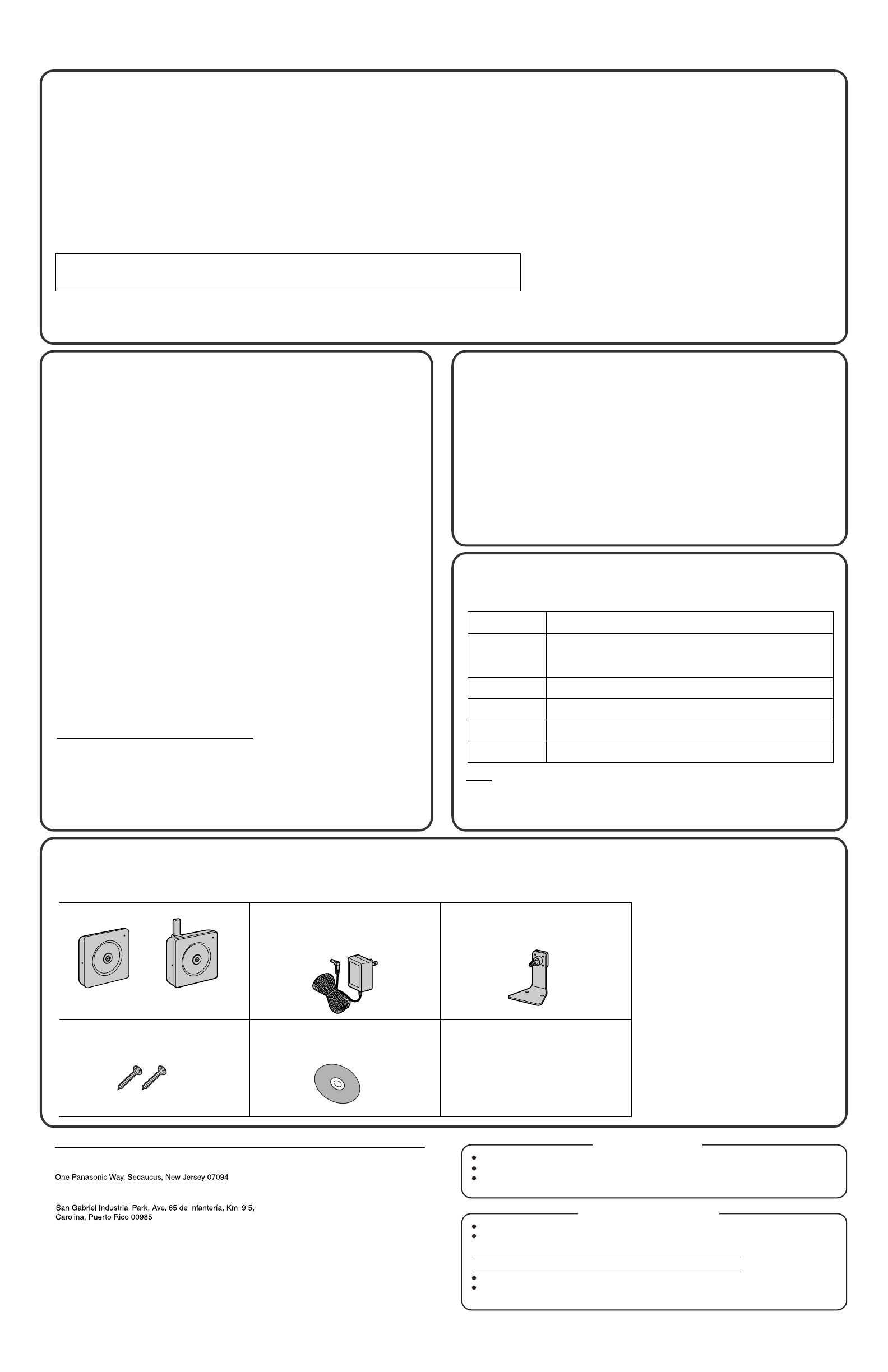
Setup CD-ROM . . . . . . . . . . . . . . . 1 pc.
Order No.: PQQX14943ZCD
Main Unit . . . . . . . . . . . . . . . . . . . . 1 pc.
Important Information
(This manual) . . . . . . . . . . . . . . . 1 pc.
Getting Started . . . . . . . . . . . . . 1 pc.
AC Adaptor . . . . . . . . . . . . . . . . . . 1 pc.
Order No.: PQLV206
(Cord Length: About 3 m [9 feet 10
inches])
The following items are provided with the camera.
Additional pieces can be ordered by calling 1-800-332-5368.
System Requirements for your PC
[For BL-C20A] Obstacles during Wireless Connection
Security Cautions
Included Items
The use of a unique User Name and secret Password is an
important tool that will help limit unauthorized individuals from
accessing the camera. If you choose to disable this tool, and
choose not to limit access by use of a User Name and Password,
this may result in access to the camera by unauthorized individuals.
(See page 80 of the Operating Instructions on the CD-ROM)
User Name and Password Protection
Note
See Panasonic Network Camera support website at
http://panasonic.co.jp/pcc/products/en/netwkcam/ for details about
network environment.
When using this product, take appropriate measures to avoid the following
security breaches.
• Leaks of private information via this product
• Illegal use of this product by a third party
• Interference or suspension of the use of this product by a third party
Take the following measures to avoid security breaches:
• To prevent illegal access, keep the firmware up to date
(If you do not have the latest version of firmware, this can lead to
blocked access or information leaks).
• You are responsible for the security settings, such as user name and
password, to access this product. This information should not be made
available to any third parties outside the user group.
• Mount the camera where the camera will not be stolen.
• You are responsible for this product's user information, such as videos,
still images, Internet content, etc. This information should not be made
available to any third parties outside the user group.
• When sending this product to be repaired with a company not related to
Panasonic, make back-up copies of files, if necessary, and reset this
product to factory default.
• When transferring this product to another party, make back-up copies of
files, if necessary, and reset this product to factory default.
• When disposing of this product, reset this product to factory default,
or erase information by means of electrical deletion or physical
dismantlement.
The radio wave range may decrease depending on the surrounding
environment or existence of obstacles. If obstacles such as the following
are placed between a camera and a router, radio waves will weaken.
Therefore, even if the distance between the camera and router is short, the
frame rate may decrease or images may not be displayed.
• A metallic door or shutter
• A wall with an insulation material that contains aluminum foil
• A wall made of tin
• A wall made of concrete, stone or brick
• Fireproof glass
• Several walls separated by open space
• A steel shelf
Flexible Stand . . . . . . . . . . . . . . . . 1 pc.
Order No.: PQKL10077ZA1-BM
Screws . . . . . . . . . . . . . . . . . . . . . 2 pcs.
Order No.: XTS35+20AKJM1
FCC and Other Information
CAUTION:
• [For BL-C20A] To comply with FCC RF exposure requirements in uncontrolled environment:
- This equipment must be installed and operated in accordance with provided instructions and a minimum 20 cm (8 inches) spacing must be provided
between antenna and all person's body (excluding extremities of hands, wrist and feet) during wireless modes of operation.
- This transmitter must not be co-located or operated in conjunction with any other antenna or transmitter.
•[For BL-C20A] Medical
Consult the manufacturer of any personal medical devices, such as pacemakers, to determine if they are adequately shielded from external RF (radio
frequency) energy. (The unit operates in the frequency range of 2.412 GHz to 2.462 GHz, and the power output level is 0.1 watts.) Do not use the unit
in health care facilities if any regulations posted in the area instruct you not to do so. Hospitals or health care facilities may be using equipment that
could be sensitive to external RF (radio frequency) energy.
• Any changes or modifications not expressly approved by the party responsible for compliance could void the user's authority to operate this device.
Video Recording Notice:
PLEASE NOTE that under certain circumstances, video recording may be PROHIBITED by law. This device should be used only in compliance with all applicable federal,
state and local statutes.
No responsibility will be taken by our company with respect to consequences
resulting from the use, damage or both of the camera.
When purchasing
BL-C1A
When purchasing
BL-C20A
Microsoft® Windows® XP (Home Edition, Professional),
Microsoft® Windows® 2000, Microsoft® Windows® Me,
Microsoft® Windows® 98SE