Panasonic of North America 96NBL-VT164W Network Camera User Manual
Panasonic Corporation of North America Network Camera
User manual
Precautions for use
Standard accessories
This system is designed to be used indoors. This product is not operable outdoors.
This product has no power switch.
When turning off the power, disconnect the power supply from AC adaptor.
To keep on using with stable performance
Do not use this camera in hot and humid conditions for a long time. Failure to observe this causes
component degradation resulting in life shortening of this product.
Do not expose this camera to direct heat sources such as a heater.
Do not touch the lens cover with your bare hands.
A dirty lens cover causes deterioration of picture quality.
Handle this camera with care.
Do not drop this camera, nor apply shock or vibration to this camera. Failure to observe this may
cause trouble.
About the PC monitor
Displaying the same image on a monitor for a long time may damage the monitor. It is recommend-
ed to use a screen-saver.
When an error is detected, this product will restart automatically.
This product will be inoperable for around 2 minutes after the restart just as when the power is
turned on.
Product disposal/transfer
Data saved on this product or a storage device used with this product may lead to personal
information leakage. When it is necessary to dispose or give this product to someone, even when
for repair, make sure that there is no data on this product.
Cleaning this product body
Be sure to turn off the power before cleaning. Failure to observe this may cause injury. Do not use
strong abrasive detergent when cleaning this product. Otherwise, it may cause discoloration. When
using a chemical cloth for cleaning, read the caution provided with the chemical cloth product.
Transmission interval
Image transmission interval may become slow depending on the network environment,
PC performance, shooting subject, access number, etc.
About the CMOS image sensor
When continuously shooting a bright light source such as a spotlight, the color filter of the CMOS
image sensor may have deteriorated and it may cause discoloration. Even when changing the
fixed shooting direction after continuously shooting a spotlight for a certain period, the discolor-
ation may remain.
When shooting fast-moving subjects or performing panning/tilting operations, objects crossing
the shooting area may look to be bending askew.
AVC Patent Portfolio License
THIS PRODUCT IS LICENSED UNDER THE AVC PATENT PORTFOLIO LICENSE FOR THE
PERSONAL USE OF A CONSUMER OR OTHER USES IN WHICH IT DOES NOT RECEIVE
REMUNERATION TO
(i) ENCODE VIDEO IN COMPLIANCE WITH THE AVC STANDARD (“AVC VIDEO”) AND/OR
(ii)
DECODE AVC VIDEO THAT WAS ENCODED BY A CONSUMER ENGAGED IN A PERSONAL
ACTIVITY AND/OR WAS OBTAINED FROM A VIDEO PROVIDER LICENSED TO PROVIDE AVC
VIDEO. NO LICENSE IS GRANTED OR SHALL BE IMPLIED FOR ANY OTHER USE. ADDITIONAL
INFORMATION MAY BE OBTAINED FROM MPEG LA, L.L.C.
SEE HTTP://WWW.MPEGLA.COM
Flickering
Due to the influence of lighting, flickering may sometimes happen. Select “Indoor scene(50 Hz)” or
“Indoor scene(60 Hz)” in accordance with the power supply frequency in your locality. Refer to the
Operating Instructions (included in the CD-ROM) for further information about the setting.
Under extremely strong lighting, flickering may happen even when “Indoor scene” is selected for
“Light control mode”. When the brightness (illuminance) level on the screen is set to a relatively low
level with the [Brightness] buttons, flickering may frequently happen. In such cases, either of the fol-
lowing can reduce flickering.
Moderate the illumination intensities of objects by changing the camera direction.
Set the brightness (illuminance) level on the screen to a brighter level with the [Brightness] but-
tons.
White-out on images caused by the effect of light control mode
When “Indoor scene” is selected for “Light control mode”, the tone of the brighter parts on the
screen may be deteriorated than the case when “ELC” is selected.
Color blurring on detailed drawing patterns
When there are detailed drawing patterns on images, color blurring may happen over these parts.
Consumable parts
The following are consumables: Replace them in accordance with their lives. Their lives vary
depending on use environment and conditions. Lifetime is just an indication when using the camera
at +20 °C {68 °F}.
Panning motor, tilting motor, flat cable for tilting: Approx. 0.12 million operations.
Lens and pan/tilt head
If a lens and pan/tilt head are not performed for a long period of time, the grease coating inside
these parts may become sticky. That may obstruct the parts from moving. To prevent this, move
the lens or pan/tilt head periodically.
Screw A (1 pc.) Screw B (1 pc.) Screw C (2 pcs.) Washer S (2 pcs.)
Washer M (1 pc.) Washer L (1 pc.) Safety Wire (1 pc.) AC Adaptor (1 pc.)
Installation Guide (this document) ........ (1 pc.)
Configure the settings of the camera (leaflet)
... (1 pc.)
Warranty card (P model) ....................... (1 pc.)
CD-ROM*1 ............................................ (1 pc.)
*1
The CD-ROM contains the operating instructions
and different kinds of tool software programs
.
Installation Guide
Network Camera
Model No. BL-VT164W/BL-VT164WE
BL-VT164WU
BL-VT164/BL-VT164E
BL-VT164U
Cs0212-0 PGQX1155ZA
Printed in China
Main functions
● H.264 and JPEG triple encoding
A total of 3 outputs, comprising of 2 H.264 outputs and 1 JPEG output, can be provided.
● Adaptive darkness correction mode
Corrects the blacked-out parts of dark areas of objects that have different illumination intensities.
● Panning/tilting function and preset position function
A single camera provides wide area monitoring.
● Audio features
The camera features a built-in microphone that allows you to monitor the audio while viewing live
camera images using your PC.
● Built-in Body Heat Sensor (Pyroelectric infrared sensor)
The camera features a built-in Body Heat Sensor (Pyroelectric infrared sensor), which uses
infrared rays to detect temperature differences within its range that are emitted naturally by
people, animals, etc. The sensor can also be used to trigger the camera to transfer images to
someone or somewhere, by FTP, E-mail, or HTTP.
●
Wireless LAN function (IEEE802.11 n/g/b) (BL-VT164W/BL-VT164WE/BL-VT164WU)
It is possible to monitor camera images and configure camera settings over a wireless network.
● WPS (Wi-Fi Protected Setup) function (BL-VT164W/BL-VT164WE/BL-VT164WU)
WPS enables the camera to automatically obtain the connection configuration information and the
security configuration information of the wireless router. WPS can be configured by pressing the
WIRELESS button (WPS button) (PBC method) or entering an 8 digit pin code (Pin code method)
.
Confirm the following items are included in the camera’s packaging.
Audio output: Internal speaker
Dimensions: 74 mm (W) x 74 mm (H) x 91 mm (D) {2-29/32 inches (W) x
2-29/32 inches (H) x 3-19/32 inches (D)} (excluding projection)
Mass: BL-VT164W/BL-VT164WE/BL-VT164WU: Approx. 230 g {0.5071 lbs}
BL-VT164/BL-VT164E/BL-VT164U: Approx. 220 g {0.485 lbs}
Finish: Main body: ABS resin, white
Dome section: Clear polycarbonate resin
● Camera
Image sensor: 1/4 type CMOS image sensor
Effective pixels: Approx. 1 megapixels
Scanning area: 3.89 mm (H) × 2.43 mm (V) {5/32 inches (H) × 3/32 inches (V)}
Scanning system: Progressive
Minimum illumination: Color: 0.9 lx {0.09 footcandle} (F2.8, Auto slow shutter: Off (1/30 s),
Gain: On (High))
0.06 lx {0.006 footcandle} (F2.8, Auto slow shutter: max. 16/30 s,
Gain: On (High))*
BW: 0.6 lx {0.06 footcandle} (F2.8, Auto slow shutter: Off (1/30 s),
Gain: On (High))
0.04 lx {0.004 footcandle} (F2.8, Auto slow shutter: max. 16/30 s,
Gain: On (High))*
* Converted value
Face WDR: On/Off
Gain (AGC): On(Low)/ On(Mid)/ On(High)/ Off
Adaptive black stretch: On/Off
Light control mode
setting:
Indoor scene (50 Hz/ 60 Hz)/ ELC
ELC
(Maximum exposure time):
ELC(1/30 s), ELC(3/100 s), ELC(3/120 s), ELC(2/100 s), ELC(2/120 s),
ELC(1/100 s), ELC(1/120 s), ELC(1/250 s), ELC(1/500 s),
ELC(1/1000 s), ELC(1/2000 s), ELC(1/4000 s), ELC(1/10000 s)
Auto slow shutter: Off (1/30 s), Max. 2/30 s, Max. 4/30 s, Max. 6/30 s, Max. 10/30 s,
Max. 16/30 s
Simple black & white
mode:
Off/Auto
White balance: ATW1/ ATW2/ AWC
Digital noise reduction: High/Low
Video analytics
Face detection:
On/Off (with the XML notification setting)
Privacy zone: On/Off (up to 2 zones available)
Camera title on screen: Up to 20 characters (alphanumeric characters, marks), On/Off
Video motion detection
(VMD alarm):
On/Off (available at each preset)
● Lens
Zoom ratio: Extra zoom: 1.5x (at VGA resolution)
Digital (electronic) zoom:
8x (Max 12x combined with Extra Zoom at VGA)
Focal length: 3.6 mm
Maximum aperture ratio:
1 : 2.8
Focus range: ∞ ~ 0.4 m
Angular field of view: Horizontal: 57°, Vertical: 34°
● Panning/tilting platform
Panning range: -41° - +41°
Panning speed:
Manual: Approx. 0.5 °/s - 50 °/s, Preset: Up to approx. 50 °/s
Tilting range: -32° - +10°
Tilting speed:
Manual: Approx. 0.5 °/s - 50 °/s, Preset: Up to approx. 50 °/s
Number of the preset positions:
64
Map shot: Preset map-shot
Self return:
10 s/ 20 s/ 30 s/ 1 min/ 2 min/ 3 min/ 5 min/ 10 min/ 20 min/ 30 min/ 60 min
● Wireless (BL-VT164W/BL-VT164WE/BL-VT164WU)
Antenna: 1x1 (Diversity)
Transmission method: SISO (Single Input/ Single Output) -OFDM, OFDM, DSSS
Communication standard:
IEEE802.11n/b/g
Frequency range
(center frequency)/Channel:
BL-VT164W:
2.412 GHz - 2.462 GHz (1 - 11ch)
BL-VT164WE/BL-VT164WU:
2.412 GHz - 2.472 GHz (1 - 13ch)
Data transfer rate: *1 IEEE802.11n: 6.5 - 72.2 Mbps
IEEE802.11g: 6 - 54 Mbps
IEEE802.11b: 1 - 11 Mbps
Access method: Infrastructure mode
Authentication method: Open System
Security: *2 WPA/WPA2-PSK (TKIP/AES)
WEP (64 bit/128 bit)
WPS: PBC method (push button method), PIN method (PIN code method)
Distributing, copying, disassembling, reverse compiling and reverse engineering of the software pro-
vided with this product are all expressly prohibited. In addition, exporting any software provided with
this product violating export laws is prohibited.
Copyright
As you will use this unit connected to a network, your attention is called to the following security risks.
A Leakage or theft of information through this unit
B Use of this unit for illegal operations by persons with malicious intent
C Interference with or stoppage of this unit by persons with malicious intent
It is your responsibility to take precautions such as those described below to protect yourself
against the above network security risks.
Use this unit in a network secured by a firewall, etc.
If this unit is connected to a network that includes PCs, make sure that the system is not infect-
ed by computer viruses or other malicious entities (using a regularly updated anti-virus program,
anti-spyware program, etc.).
Protect your network against unauthorized access by restricting users to those who log in with
an authorized user name and password.
Apply measures such as user authentication to protect your network against leakage or theft of
information, including image data, authentication information (user names and passwords), alarm
E-mail information, FTP server information and DDNS server information.
After the unit is accessed by the administrator, make sure to close the browser.
Change the administrator password periodically.
Do not install the camera in locations where the camera or the cables can be destroyed or dam-
aged by persons with malicious intent.
Network security
● Network
Network: 10BASE-T/100BASE-TX, RJ45 connector
Resolution: Imaging mode: 4:3
H.264 SVGA (800x600)/ VGA (640x480)/ QVGA (320x240) max.30 fps
JPEG SVGA (800x600)/ VGA (640x480)/ QVGA (320x240) max.30 fps
Imaging mode: 16:9
H.264 1280x720/ 640x360/ 320x180 max.30 fps
JPEG 1280x720/ 640x360/ 320x180 max.30 fps
Image compression
method: *3
H.264 Image quality: Low/ Normal/ Fine
Transmission type: Unicast/Multicast
Bit rate:
Constant bit rate:
64 kbps/ 128 kbps/ 256 kbps/ 384 kbps/ 512 kbps/
768 kbps/ 1024 kbps/ 1536 kbps/ 2048 kbps/ 3072 kbps/
4096 kbps/ 8192 kbps
Frame rate:
1 fps/ 3 fps/ 5 fps/ 7.5 fps/ 10 fps/ 12 fps/ 15 fps/ 20 fps/ 30 fps
JPEG Image quality: 0 SUPER FINE/ 1 FINE/ 2/ 3/ 4/ 5 NORMAL/
6/ 7/ 8/ 9 LOW (10 steps: 0-9)
Transmission type: PULL/PUSH
Transmission interval: 0.1 fps - 30 fps (JPEG frame rate will be restricted when displaying
both JPEG and H.264/ images.)
Audio compression
method:
G.726 (ADPCM) 32 kbps/ 16 kbps
G.711 64 kbps
Bandwidth control: Unlimited/ 64 kbps/ 128 kbps/ 256 kbps/ 384 kbps/ 512 kbps/
768 kbps/ 1024 kbps/ 2048 kbps/ 4096 kbps/ 8192 kbps
Protocol: IPv6: TCP/IP, UDP/IP, HTTP, HTTPS, RTP, FTP, SMTP, DNS, NTP,
SNMP, DHCPv6, MLD, ICMP, ARP
IPv4:
TCP/IP, UDP/IP, HTTP, HTTPS, RTSP, RTP, RTP/RTCP, FTP, SMTP,
DHCP, DNS, DDNS, NTP, SNMP, UPnP, IGMP, ICMP, ARP
Maximum concurrent
access number:
14 (Depends on network conditions)
FTP client: Alarm image transmission, FTP periodic transmission
Multi-screen: Up to 16 camera images can be displayed simultaneously on a multi-
screen. (Including the camera itself)
Cellular phone compatibility:
JPEG image, panning/tilting/zoom/Privacy control,
AUX control (by access level)
Mobile terminal
compatibility
(As of January, 2012): *4
iPad, iPhone, iPod touch (iOS 4.2.1 or later)
AndroidTM mobile terminals
● Body heat sensor
Sensor detection method: pyroelectric infrared sensor
Sensitivity settings: Off/ High/ Normal/ Low/ Quiet
Sensor detection range: About 5 m (with the temperature at 20 °C and Normal sensitivity)
Horizontal: 28°, Vertical: 71°
*1 The actual line speed may be different depending on the network environment and the wireless
devices connected.
*2 Depending on the wireless router (wireless access point) used, connections may not possible
between the camera and the wireless router.
When connecting with 802.11n, select WPA-PSK (AES) or WPA2-PSK (AES) for security.
*3 Transmission for 2 streams can be individually set in the same compression method.
*4 For further information about compatible devices, refer to our website
(http://panasonic.net/pss/security/support/info.html).
● Optional accessories
User License Accessory (For H.264) BB-HCA8A (P model)
BB-HCA8CE (E model, U model)
Before asking for repairs, check the symptoms with the following table.
Contact your dealer if a problem cannot be solved even after checking and trying the solution in the
table or a problem is not described below.
Symptom Cause/solution
Power is not turned on. u
Is 9 V DC power supply connected to the power supply terminal?
Check whether the connection is appropriately established.
Is the AC adaptor in use compliant with the Specifications?
Check the Specifications regarding AC adaptor.
Use only with Panasonic AC adapter.
Troubleshooting
Important safety instructions
1) Read these instructions.
2) Keep these instructions.
3) Heed all warnings.
4) Follow all instructions.
5) Do not use this apparatus near water.
6) Clean only with dry cloth.
7) Do not install near any heat sources such as radiators, heat registers, stoves, or other appara-
tus (including amplifiers) that produce heat.
8) Protect the power cord from being walked on or pinched particularly at plugs, convenience
receptacles, and the point where they exit from the apparatus.
9) Only use attachments/accessories specified by the manufacturer.
10) Unplug this apparatus during lightning storms or when unused for long periods of time.
11) Refer all servicing to qualified service personnel. Servicing is required when the apparatus has
been damaged in any way, such as power-supply cord or plug is damaged, liquid has been
spilled or objects have fallen into the apparatus, the apparatus has been exposed to rain or
moisture, does not operate normally, or has been dropped.
Limitation of liability
THIS PUBLICATION IS PROVIDED “AS IS” WITHOUT WARRANTY OF ANY KIND, EITHER
EXPRESS OR IMPLIED, INCLUDING BUT NOT LIMITED TO, THE IMPLIED WARRANTIES OF
MERCHANTABILITY, FITNESS FOR ANY PARTICULAR PURPOSE, OR NON-INFRINGEMENT OF
THE THIRD PARTY’S RIGHT.
THIS PUBLICATION COULD INCLUDE TECHNICAL INACCURACIES OR TYPOGRAPHICAL
ERRORS. CHANGES ARE ADDED TO THE INFORMATION HEREIN, AT ANY TIME, FOR THE
IMPROVEMENTS OF THIS PUBLICATION AND/OR THE CORRESPONDING PRODUCT (S).
Disclaimer of warranty
IN NO EVENT SHALL Panasonic System Networks Co., Ltd. BE LIABLE TO ANY PARTY OR ANY
PERSON, EXCEPT FOR REPLACEMENT OR REASONABLE MAINTENANCE OF THE PRODUCT,
FOR THE CASES, INCLUDING BUT NOT LIMITED TO BELOW:
(1) ANY DAMAGE AND LOSS, INCLUDING WITHOUT LIMITATION, DIRECT OR INDIRECT, SPECIAL,
CONSEQUENTIAL OR EXEMPLARY, ARISING OUT OF OR RELATING TO THE PRODUCT;
(2) PERSONAL INJURY OR ANY DAMAGE CAUSED BY INAPPROPRIATE USE OR NEGLIGENT
OPERATION OF THE USER;
(3) ALL MALFUNCTIONS OR TROUBLES FROM UNAUTHORIZED DISASSEMBLE, REPAIR OR
MODIFICATION OF THE PRODUCT BY THE USER, REGARDLESS OF THE CAUSE OF THE
MALFUNCTION OR TROUBLE;
(4) INCONVENIENCE OR ANY LOSS ARISING WHEN IMAGES ARE NOT DISPLAYED, DUE TO
ANY REASON OR CAUSE INCLUDING ANY FAILURE OR PROBLEM OF THE PRODUCT;
(5) ANY PROBLEM, CONSEQUENTIAL INCONVENIENCE, OR LOSS OR DAMAGE, ARISING
OUT OF THE SYSTEM COMBINED BY THE DEVICES OF THIRD PARTY;
(6) ANY CLAIM OR ACTION FOR DAMAGES, BROUGHT BY ANY PERSON OR ORGANIZATION
BEING A PHOTOGENIC SUBJECT, DUE TO VIOLATION OF PRIVACY WITH THE RESULT OF
THAT SURVEILLANCE-CAMERA’S PICTURE, INCLUDING SAVED DATA, FOR SOME
REASON, BECOMES PUBLIC OR IS USED FOR ANY PURPOSE;
(7) LOSS OF REGISTERED DATA CAUSED BY ANY FAILURE.
For U.S. and Canada:
Panasonic System Communications
Company of North America,
Unit of Panasonic Corporation of North America
www.panasonic.com/business/
For customer support, call 1.800.528.6747
Three Panasonic Way, Secaucus, New Jersey 07094 U.S.A.
Panasonic Canada Inc.
5770 Ambler Drive, Mississauga, Ontario, L4W 2T3 Canada
(905)624-5010
www.panasonic.ca
© Panasonic System Networks Co., Ltd. 2012
For Europe and other countries:
http://panasonic.net
Importer’s name and address to follow EU rules:
Panasonic Testing Centre
Panasonic Marketing Europe GmbH
Winsbergring 15, 22525 Hamburg F.R.Germany
Information for Users on Collection and Disposal of Old Equipment and used Batteries
These symbols on the products, packaging, and/or accompanying documents mean
that used electrical and electronic products and batteries should not be mixed with
general household waste.
For proper treatment, recovery and recycling of old products and used batteries,
please take them to applicable collection points, in accordance with your national leg-
islation and the Directives 2002/96/EC and 2006/66/EC.
By disposing of these products and batteries correctly, you will help to save valuable
resources and prevent any potential negative effects on human health and the envi-
ronment which could otherwise arise from inappropriate waste handling.
For more information about collection and recycling of old products and batteries,
please contact your local municipality, your waste disposal service or the point of sale
where you purchased the items.
Penalties may be applicable for incorrect disposal of this waste, in accordance with
national legislation.
For business users in the European Union
If you wish to discard electrical and electronic equipment, please contact your dealer
or supplier for further information.
Cd
[Information on Disposal in other Countries outside the European Union]
These symbols are only valid in the European Union. If you wish to discard these items,
please contact your local authorities or dealer and ask for the correct method of disposal
.
Note for the battery symbol (bottom two symbol examples):
This symbol might be used in combination with a chemical symbol. In this case it
complies with the requirement set by the Directive for the chemical involved.
For BL-VT164W/BL-VT164WE/BL-VT164WU
Operating near 2.4 GHz electrical appliances may cause interference. Move away from the
electrical appliances.
- This equipment must be installed and operated in accordance with provided instructions and
a minimum 20 cm {8 inches} spacing must be provided between antenna and all person’s
body (excluding extremities of hands, wrist and feet) during wireless modes of operation.
- This transmitter must not be co-located or operated in conjunction with any other antenna or
transmitter.
MEDICAL:
Consult the manufacturer of any personal medical devices, such as pacemakers, to determine if
they are adequately shielded from external RF (radio frequency) energy. (The unit operates in the
frequency range of 2.412 GHz to 2.462 GHz (BL-VT164W), 2.412 GHz to 2.472 GHz
(BL-VT164WE/BL-VT164WU).) Do not use the unit in health care facilities if any regulations
posted in the area instruct you not to do so. Hospitals or health care facilities may be using
equipment that could be sensitive to external RF (radio frequency) energy.
For U.S.A
The model number and serial number of this product may be found on the surface of the unit.
You should note the model number and serial number of this unit in the space provided and
retain this book as a permanent record of your purchase to aid identification in the event of theft.
Model No. _________________________________
Serial No. __________________________________
For European Union (EU) (BL-VT164E/BL-VT164U)
We declare under our sole responsibility that the product to which this declaration relates is in
conformity with the standards or other normative documents following the provisions of
Directives 2006/95/EC and 2004/108/EC.
Wir erklären in alleiniger Verantwortung, daß das Produkt, auf das sich diese Erklärung bezieht,
mit den folgenden Normen oder normativen Dokumenten übereinstimmt. Gemäß den
Bestimmungen der Richtlinie 2006/95/EC und 2004/108/EC.
Nous déclarons sous notre propre responsabilité que le produit auquel se réfère la présente
déclaration est conforme aux normes spécifiées ou à tout autre document normatif conformé-
ment aux dispositions des directives 2006/95/CE et 2004/108/CE.
Nosotros declaramos bajo nuestra única responsabilidad que el producto a que hace referencia
esta declaración está conforme con las normas u otros documentos normativos siguiendo las
estipulaciones de las directivas 2006/95/CE y 2004/108/CE.
Noi dichiariamo sotto nostra esclusiva responsabilità che il prodotto a cui si riferisce la presente
dichiarazione risulta conforme ai seguenti standard o altri documenti normativi conformi alle dis-
posizioni delle direttive 2006/95/CE e 2004/108/CE.
Wij verklaren als enige aansprakelijke, dat het product waarop deze verklaring betrekking heeft,
voldoet aan de volgende normen of andere normatieve documenten, overeenkomstig de bepal-
ingen van Richtlijnen 2006/95/EC en 2004/108/EC.
Vi erklærer os eneansvarlige for, at dette produkt, som denne deklaration omhandler, er i over-
ensstemmelse med standarder eller andre normative dokumenter i følge bestemmelserne i direk-
tivene 2006/95/EC og 2004/108/EC.
Vi deklarerar härmed vårt fulla ansvar för att den produkt till vilken denna deklaration hänvisar är i
överensstämmelse med de standarder eller andra normativa dokument som framställs i direktiv
nr 2006/95/EC och 2004/108/EC.
Ilmoitamme yksinomaisella vastuullamme, että tuote, jota tämä ilmoitus koskee, noudattaa
seuraavia standardeja tai muita ohjeellisia asiakirjoja, jotka noudattavat direktiivien 2006/95/EC ja
2004/108/EC säädöksiä.
Vi erklærer oss alene ansvarlige for at produktet som denne erklæringen gjelder for, er i overens-
stemmelse med følgende normer eller andre normgivende dokumenter som følger bestem-
melsene i direktivene 2006/95/EC og 2004/108/EC.
For European Union (EU) (BL-VT164WE/BL-VT164WU)
Panasonic System Networks Co., Ltd., declares that this equipment is in compliance with the
essential requirements and other relevant provisions of Radio & Telecommunications Terminal
Equipment (R&TTE) Directive 1999/5/EC.
Declarations of Conformity for the relevant Panasonic products described in this manual are
available for download by visiting:
http://www.doc.panasonic.de
Contact:
Panasonic Services Europe
a Division of Panasonic Marketing Europe GmbH
Panasonic Testing Centre
Winsbergring 15, 22525 Hamgurg, F.R. Germany
AT BE BG CY CZ DK
EE FI FR DE GR HU
IE IT LV LT LU MT
NL PL PT RO SK SI
ES SE GB IS LI NO
CH HR MK TR
● Basic
Power source: 9 V DC (Use only with Panasonic AC adapter)
Power consumption:
BL-VT164W/BL-VT164WE/BL-VT164WU: max 4.8 W
BL-VT164/BL-VT164E/BL-VT164U: max 3.7 W
Ambient operating temperature:
0 °C to +40 °C {32 °F to 104 °F}
Ambient operating humidity:
less than 90 % (No condensation)
External I/O terminals:
ALARM IN 1, ALARM IN 2/ ALARM OUT, ALARM IN 3/ AUX OUT, GND
Microphone/line input: Internal microphone
(This illustration represents BL-VT164W.)
Option
System requirements for a PC
About the user manuals
You will need the following additional items to install and configure the camera.
[Locally procured]
a PC (used to view settings and images)
a router/ a wireless router (when using the wireless function)
a LAN cable (CAT-5 straight cable)
Refer to “Configure the settings of the camera” (leaflet) for information about the system require-
ments for a PC.
There are 3 sets of operating instructions for the BL-VT164W/BL-VT164 (P model), BL-VT164WE/
BL-VT164E (E model), BL-VT164WU/BL-VT164U (U model) as follows.
Installation Guide: Explains how to install and connect devices.
Configure the settings of the camera (leaflet): Explains how to configure the network.
Operating Instructions (included in the CD-ROM): Explains how to perform the settings and how
to operate this camera.
Adobe® Reader® is required to read these operating instructions on the provided CD-ROM.
When the Adobe Reader is not installed on the PC, download the latest Adobe Reader from the
Adobe web site and install it.
“BL-VT164W, BL-VT164” or “VT164W, VT164” shown in the instructions and illustrations used in
these operating instructions indicates the BL-VT164W, BL-VT164WE, BL-VT164WU, BL-VT164,
BL-VT164E, BL-VT164U.
The screens used in these operating instructions show the cases of P models.
Precautions
WARNING
CAUTION
Turn the power off when cleaning this product.
• Failure to observe this may cause injury.
Disconnect the AC cord when not using the unit for extended periods of time or
•
when performing maintenance.
Failure to observe this may cause an earth leakage or electric shock.
Refer installation work to the dealer.
• Installation work requires technique and experiences. Failure to observe this may cause fire,
electric shock, injury, or damage to the product.
Be sure to consult the dealer.•
Stop the operation immediately when something is wrong with this product.
• When smoke goes up from the product, the smell of smoke comes from the product, or the
exterior of the product has deteriorated, continued use will cause a fire or fall of the product
resulting in injury, or damage to the product.
Turn the power off immediately and contact qualified service personnel for service.•
Select an installation area that can support the total weight.
• Selecting an inappropriate installation surface may cause this product to fall down or topple
over, resulting in injury.
Installation work shall be started after sufficient reinforcement.•
Periodic inspections shall be conducted.
• Rust on the metal parts or screws may cause a fall of the product resulting in injury or accidents.
Consult the dealer for the inspections.•
The screws and bolts must be tightened to the specified torque.
• Failure to observe this may cause a drop resulting in injury or accidents.
Do not install this product in locations subject to vibration.
• Loosening of mounting screws or bolts may cause a fall of the product resulting in injury.
Make sure that the screws and bolts are tightened firmly.
The measures of protection against a fall of this product shall be taken.
•
Failure to observe this may cause a drop resulting in injury or accidents. Be sure to install the safety wire.
Install this product in a location high enough to avoid people and objects from
•
bumping the product.
Failure to observe this may cause a drop resulting in injury or accidents.
Do not attempt to disassemble or modify this product.
• Failure to observe this may cause fire or electric shock. Consult the dealer for the repair or
inspections.
Do not insert any foreign objects.
• This could permanently damage this product. Turn the power off immediately and contact
qualified service personnel for service.
Do not use this product in an inflammable atmosphere.
• Failure to observe this may cause an explosion resulting in injury.
Avoid installing this product in the locations where salt damage occurs or
•
corrosive gas is produced.
Otherwise, the mounting portions will deteriorate and accidents such as a fall of the product may occur.
Do not strike or give a strong shock to this product.
• Failure to observe this may cause fire or injury.
Do not rub the edges of metal parts with your hand.
• Failure to observe this may cause injury.
Do not touch this product or the connected cables during thunder (even in the
•
process of work).
Failure to observe this may cause electric shock.
Fully insert the AC cord plug into the power outlet.
• Do not use damaged plugs or unstable power outlets.
Failure to observe this may cause electric shock or heat generation resulting in a fire.
When disconnecting or connecting the AC adaptor, do not hold the metal parts
•
of the plug.
Failure to observe this may cause electric shock.
Periodically remove dust or other materials from the AC adaptor and its plug part.
•
Disconnect the AC adaptor and wipe the AC adaptor and its plug part with a dry cloth to
remove dust. A fire may be caused if dust or other materials accumulate on the plug part of the
AC adaptor and become moist from humidity.
Use only a dedicated AC cord plug (polarized type).
• If other AC cord plugs are used, the voltage and positive/negative polarities may differ and this
may cause fire or electric shock.
Do not insert/remove the AC cord plug with wet hands.
• Failure to observe this may cause electric shock.
Do not overload the power outlet or wiring above the specified levels.
• Overloading by having many connections on one power outlet may cause heat generation
resulting in a fire.
Do not damage the AC cord or AC cord plug.
• Do not damage, fabricate, twist, stretch, bundle, or forcibly bend the power cable or AC cord
plug. Do not place heavy objects on the power cable or AC cord plug. Keep the power cable
and AC cord plug away from heat sources. Using a damaged power cable or AC cord plug
may cause electric shock, short circuit, or fire. Consult the dealer for repair.
Unplug this unit from power supply if it emits smoke, an abnormal smell or
•
makes unusual noise, has been dropped or is damaged in any way.
These conditions can cause fire or electric shock. Stop using the unit and contact an autho-
rized service center.
Do not damage internal wiring or plumbing when opening holes in ceiling or
•
walls for installation or wiring, fixing AC cords, extension cords, or LAN cables,
etc. or performing any other installations.
Failure to observe this may cause earth leakage, electric shock, or fire.
Perform all electrical wiring in accordance with the relevant electrical
•
installation and wiring precautions and regulations.
Incorrect electrical wiring may cause fire or electrical shock.
Have all electrical wiring perform by a licensed electrician.
Do not place containers or other objects that contain water or other liquids on
•
top of the unit.
Fire or electrical shock may be caused if water or other liquids enter inside the unit.
If water or other liquids enter inside the unit, immediately disconnect the AC cord and contact
an authorized service center.
Do not use AC cords from other products.
• Failure to observe this may cause fire or electric shock.
Adobe, Acrobat Reader, and Reader are either registered trademarks or trademarks of Adobe
Systems Incorporated in the United States and/or other countries.
iPad, iPhone, and iPod touch are registered trademarks of Apple Inc., registered in the U.S. and
other countries.
Android is a trademark of Google Inc. Use of this trademark is subject to Google Permissions.
All other trademarks identified herein are the property of their respective owners.
Trademarks and registered trademarks
Specications
WARNING:
To prevent fire or electric shock hazard, do not expose this apparatus to rain or moisture.
To prevent injury, this apparatus must be securely attached to the floor/wall/ceiling in accor-
dance with the installation instructions.
The mains plug or an appliance coupler shall remain readily operable.
The apparatus should not be exposed to dripping or splashing and that no objects filled
with liquids, such as vases, should be placed on the apparatus.
For U.S.A
This product contains a CR Coin Cell Lithium Battery which contains Perchlorate Material - special
handling may apply. See
www.dtsc.ca.gov/hazardouswaste/perchlorate/
For U.S.: BL-VT164W
For U.S. and Canada: BL-VT164
For Europe and other countries: BL-VT164WE, BL-VT164WU, BL-VT164E, BL-VT164U
UL listed model No. BL-VT164W, BL-VT164
For Canada
This Class B digital apparatus complies with Canadian ICES-003.
For U.S.A
NOTE: This equipment has been tested and found to comply with the limits for a Class B digital
device, pursuant to Part 15 of the FCC Rules. These limits are designed to provide reasonable
protection against harmful interference in a residential installation. This equipment generates,
uses and can radiate radio frequency energy and, if not installed and used in accordance with
the instructions, may cause harmful interference to radio communications. However, there is no
guarantee that interference will not occur in a particular installation.
If this equipment does cause harmful interference to radio or television reception, which can be
determined by turning the equipment off and on, the user is encouraged to try to correct the
interference by one or more of the following measures:
- Reorient or relocate the receiving antenna.
- Increase the separation between the equipment and receiver.
- Connect the equipment into an outlet on a circuit different from that to which the receiver is
connected.
- Consult the dealer or an experienced radio/TV technician for help.
This device complies with part 15 of the FCC Rules. Operation is subject to the following two
conditions:
(1) This device may not cause harmful interference, and (2) this device must accept any
interference received, including interference that may cause undesired operation.
CAUTION:
Any
changes or modifications not expressly approved by the party responsible for compliance
could void the user’s authority to operate the equipment.
Before attempting to connect or operate this product, please read these instructions
carefully and save this manual for future use.
The model number is abbreviated in some descriptions in this manual.
3 Connections
1 Check the installing place
2 Major operating controls
Determining the mounting position
Precautions for Installation
About the range of use for wireless communication
(BL-VT164W, BL-VT164WE, BL-VT164WU)
¢ Installing the camera on the wall
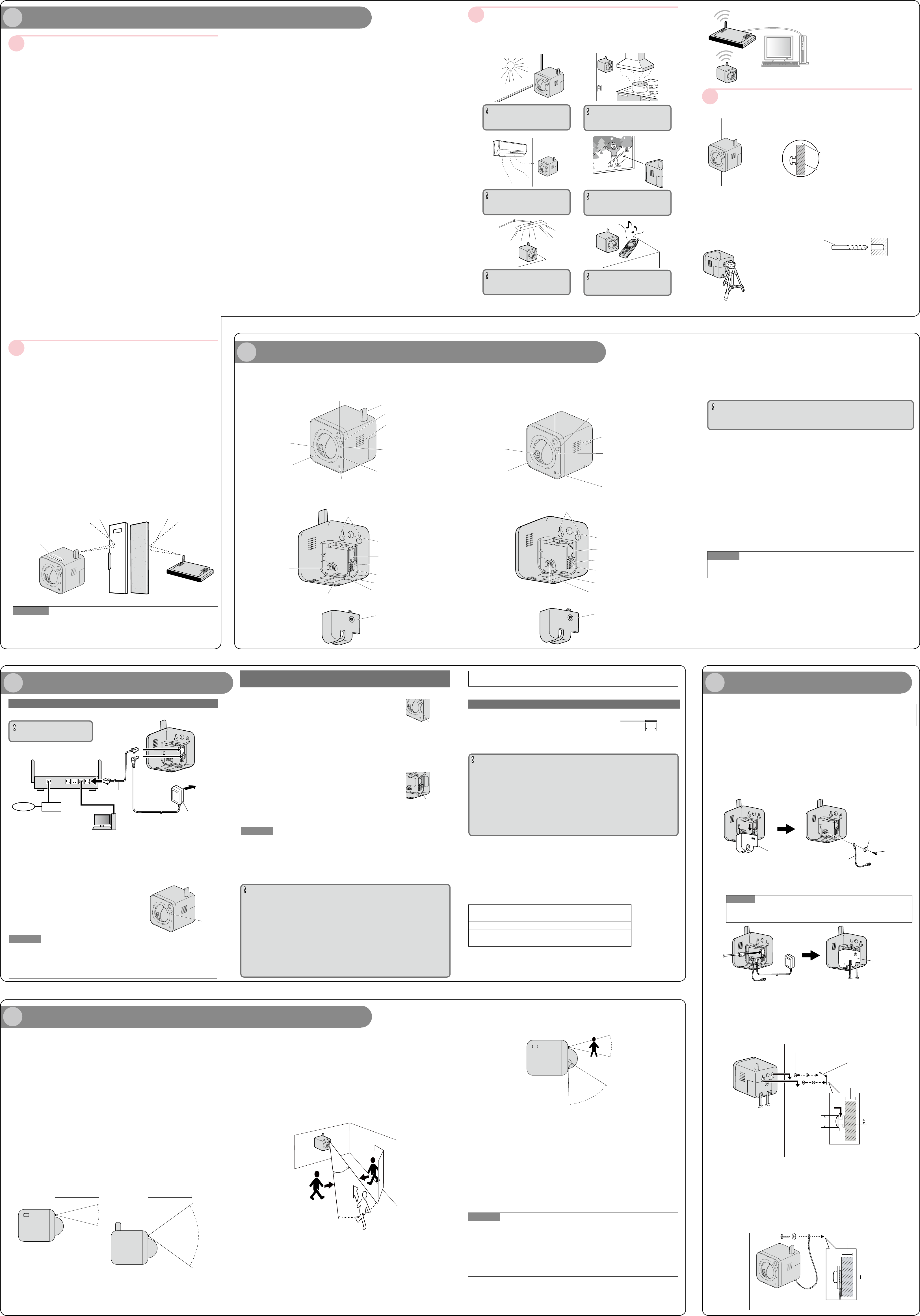
Make sure the flexible stand is firmly mounted on a beam of wood (25 mm
{31/32 inches} and greater) etc. When there is no beam, apply a board on
the other side of the wall to make sure the camera does not drop.
When mounting on a mortar or concrete surface
Prepare anchors for 4 mm {5/32 inches} diameter screws for mounting.
Mortar walls break easily when drilling. Be careful of pieces of mortar
which may become loose and fall.
1.
Place the flexible stand on the wall where you plan to mount the flexible
stand and mark the points where you are going to make holes.
2. Make holes with an electric drill. Insert anchors (locally procured)
into the holes and push them inside the holes with a hammer.
3. Mount the flexible stand using the screws.
Drill for concrete (in case of
tile, use a drill for tile)
Determining how to mount the camera
¢ Tripod Mount
Do not use a tripod screw with a thread of 6 mm {1/4 inches} or more.
This may damage the tripod mounting hole.
The camera cannot be mounted depending on the shape of the camera
platform.
* When the camera is installed to a tripod mount, because the center of
gravity is moved forward, the tripod may fall over.
Beam of wood
At least 25 mm {31/32 inches}
The camera's built-in Body Heat Sensor is a pyroelectric infrared sensor, which may
not perform properly in the following areas. Avoid these kinds of locations when
mounting the camera.
(This illustration represents BL-VT164W.)
IMPORTANT
Where the camera or the object is
exposed to direct sunlight
IMPORTANT
In a greasy or humid place such as a
kitchen
IMPORTANT
Where there are sharp temperature
changes such as near an air conditioner
IMPORTANT
Where there is an obstacle such as
glass in front of the camera
IMPORTANT
Where the camera or the object is
exposed to bright light
IMPORTANT
Near devices that emit radio waves,
such as mobile phones
Panasonic assumes no responsibility for injuries or property damage resulting
from failures arising out of improper installation or operation inconsistent with
this documentation
.
This camera is designed to be used indoors.
This camera is not operable outdoors.
Do not expose this camera to direct sunlight for hours and do not install the product
near a heater or an air conditioner. Otherwise, it may cause deformation, discoloration
and malfunction. Keep this camera away from water and moisture.
Do not place this product in the following places:
Locations where it may get wet from rain or water splash
Locations where a chemical agent is used such as a swimming pool
Locations subject to humidity, dust, steam and oil smoke
Locations that have a specific environment that is subject to an inflammable atmosphere or solvents
Locations where a radiation, an X-ray, a strong radio wave or a strong magnetic field
is generated
Locations where corrosive gas is produced, Locations where it may be damaged by
briny air such as seashores
Locations where the temperature is not within the specified range (0 °C to +40 °C
{32 °F to +104 °F}).
Locations subject to vibrations (This product is not designed for on-vehicle use.)
Locations subject to condensation as the result of severe changes in temperature
Be sure to remove this product if it is not in use.
Before installation
When this camera is mounted on a wooden wall, use the wood screws (accessory,
Screw B). Screws to be used for other materials are not provided. Prepare the screws
according to the material, structure, strength and other factors of the mounting area and
the total weight of objects to be mounted
.
Ensure that the mounting surface, anchor and screws are sufficiently strong.
Do not mount this product on a plaster board or a wooden section because they are
too weak. If this product is unavoidably mounted on such a section, the section shall
be sufficiently reinforced
.
Design and engineer the power supply system to turn on/off the power
of this product.
The product has no power switch. When installing the product, disconnect the AC
adaptor and use a power supply device equipped with the ON-OFF switch for servicing
.
About the network connection
When connecting to a network using the network cable of this product, observe the fol-
lowing. When wiring for the network, design and engineer not to be affected by thunder
.
Screw tightening
The screws must be tightened with an appropriate tightening torque according to
the material and strength of the installation area.
Do not use an impact driver. Use of an impact driver may damage the screws or
cause tightening excessively.
When a screw is tightened, make the screw at a right angle to the surface. After tightening
the screws, perform visual check to ensure tightening is enough and there is no backlash
.
Fall prevention measures
When the external safety wire is connected, select a connection point resulting in that
nothing will hit people after the stand is damaged.
Do not remove or loosen the internal camera screws.
Do not loosen the internal camera screws. Otherwise, water exposure may cause
damage or malfunction of camera, or camera dropping may result in injury.
Radio disturbance
When this product is used near TV/radio antenna, strong electric field or magnetic field
(near a motor, a transformer or a power line), images may be distorted and noise
sound may be produced.
Router
When connecting this product to the Internet, use a broadband router with the port for-
warding function (NAT, IP masquerade). Refer to the Operating Instructions (included in
the CD-ROM) for further information about the port forwarding function. Configure the
wireless settings of the camera to match the wireless settings of the router. For infor-
mation on the wireless settings of the router, refer to the operating instructions included
with your wireless router.
Time & date setting
It is necessary to set the time & date before putting this product into operation. Refer to
the Operating Instructions on the provided CD-ROM for descriptions of how to perform
the settings.
About the [INITIAL SET] button
After turning off the power of the camera, turn on the power of the camera while holding down
this button, and wait for around 5 seconds or more without releasing this button. Wait around
3 minutes after releasing the button. The camera will start up and the settings including the
network settings will be initialized. Before initializing the settings, it is recommended to write
down the settings in advance. The initialization will be complete when the POWER indicator
stops blinking orange and lights off. Note that the preset position settings and the CRT key
(SSL encryption key) used for the HTTPS protocol will not be initialized.
IMPORTANT
Do not turn off the power of the camera during the process of initialization. Otherwise,
it may fail to initialize and may cause malfunction.
About the [PRIVACY] button
Privacy mode allows you to protect your privacy by hiding the lens inside the camera, prevent-
ing camera images from being seen. You can turn privacy mode on by pressing the PRIVACY
button on the front of the camera.
When privacy mode is turned on, the PRIVACY button (which also serves as the camera’s
POWER indicator) changes from green to red to let you know that privacy mode is activated.
To turn privacy mode off and allow the camera to be accessed, simply press the PRIVACY
button again. It should turn green within a few seconds.
If users are accessing the camera when privacy mode is turned on, the camera image area
displayed in their web browsers turns into a black image display. No camera pages can be
accessed by users while privacy mode is turned on. Once privacy mode is turned off, users
can press the refresh button in their web browsers to view images again.
The camera’s administrator can also turn privacy mode on and off using a PC or a mobile
phone, and the PRIVACY button itself can be disabled so that privacy mode cannot be turned
on or off by pressing the PRIVACY button.
For more information about privacy mode, see Privacy Mode in the Operating Instructions
(included in the CD-ROM).
Note
If you plan on using the PRIVACY button to turn privacy mode on and off, make sure you
mount the camera where you can reach the button.
About the POWER indicator and the WIRELESS indicator (WPS indicator)
For more information, see Configure the basic settings [Basic] in the Operating Instructions
(included in the CD-ROM).
Built-in Body Heat Sensor
(pyroelectric infrared sensor)
<BL-VT164W/BL-VT164WE/BL-VT164WU>
Antenna
PRIVACY button
POWER indicator
WIRELESS indicator (WPS indicator)
Wall mounting holes
Tripod mounting hole
Serial number and MAC
address label
External I/O interface
DC IN jack
LAN port
WIRELESS button (WPS button)
INITIAL SET button
Cable cover
<Rear View>
Lens cover
Lens
Speaker
Microphone
Safety wire hole
<BL-VT164/BL-VT164E/BL-VT164U>
Notes About the Camera’s Built-in Body Heat Sensor
(This illustration represents BL-VT164W.)
Please read the following information about the camera’s built-in Body Heat Sensor (Pyroelectric
infrared sensor) before deciding where to mount the camera.
Refer to the Panasonic Network Camera website at
http://panasonic.net/pss/security/support/info.html for further information
about the built-in Body Heat Sensor.
The camera’s built-in Body Heat Sensor is a pyroelectric infrared sensor, which means it uses
infrared rays to detect temperature differences within its range that are emitted naturally by people,
animals, etc. The sensor can be used to trigger the camera to buffer (i.e., temporarily store) camera
images in its memory. You can view these images later as desired. The sensor can also be used to
trigger the camera to transfer images to someone or somewhere, by FTP, E-mail, or HTTP.
Because the detection range is easily affected by the temperature of the surrounding environment
or how fast the objects in front of the camera are moving, you should take the following into con-
sideration when deciding where to mount the camera.
1 The sensor’s active detection range is about 5 m {3/16 inches} in front
of the camera, about 28º horizontally, and about 71º vertically, when
the camera is in a 20 ºC (68 ºF) environment.
2 If an object is within about 1 m {1/32 inches} of the camera, the sensor
may detect the object even if it is outside of the sensor’s range.
4 Choosing a Location to Mount the Camera
3 If there is no temperature difference between objects in range of the
camera’s sensor and the surrounding environment, such as on a hot
summer day, the sensor may not be able to detect properly.
4 If the sensor is obstructed, the sensor is not able to make detections.
Remove any obstacles in front of the sensor.
5 As shown in the illustration below, the sensor can easily detect
temperature differences of objects moving sideways within the detection
range, but cannot easily detect objects moving slowly towards the sensor.
Mount the camera where objects often pass the camera from the sides.
6 If the lens is aimed at an area outside of the sensor’s active detection
range, the objects that trigger the sensor may not be visible, and therefore
buffered or transferred images may not show the object that triggered the
sensor.
In the example below, the person has triggered the sensor, but the person is not in the
visible range of the camera.
We recommend that you limit the pan and tilt range of the camera to the active detec-
tion range of the sensor, or that you limit other user’s access to the pan and tilt features.
7 The sensor may not perform properly in some areas.
Refer to “Determining the mounting position” when mounting the camera.
8 When deciding where to mount the camera, you can verify the sensor’s
ability to make detections that satisfy your needs by referring to the
camera’s POWER indicator. See Configure the basic settings [Basic] in
the Operating Instructions (included in the CD-ROM), and configure the
camera to light the POWER indicator in orange when the sensor makes
a detection. You can then adjust the sensitivity of the sensor (see
Configure the settings relating to the alarm action [Alarm] in the
Operating Instructions (included in the CD-ROM)) or change the
camera’s location if necessary. Note that if you increase the sensitivity of
the sensor, the sensor may make inaccurate detections.
Note
If you are not satisfied with the sensor’s ability to make detections, we recommend using
the camera’s motion detection feature. This feature detects motion by detecting changes in
the camera image. For more information, see Configure the VMD settings [VMD area] in the
Operating Instructions (included in the CD-ROM).
The built-in sensor and the motion detection feature are not designed to be used for securi-
ty or surveillance. No responsibility will be taken by our company with respect to conse-
quences resulting from the use of these features.
Easy to detect
Easy to detect
Difficult to detect
(The detection range may
be reduced)
About 5 m
{3/16 inches}
About 5 m
{3/16 inches}
About 28°
About 71°
Top View Side View
28º
57º
5 Mounting the Camera
Before installing the camera, check that the camera settings have been
completed. Refer to “Configure the settings of the camera” (leaflet).
Installing the camera on the wall
(This illustration represents BL-VT164W.)
Adjust the camera to a suitable position/direction while confirming the images actually displayed
on the computer screen.
1 Remove the cable cover, secure the safety wire to the camera
using screw B (accessory) and washer M (accessory).
(Recommended tightening torque: 1.6 N·m {1.18 lbf·ft})
Make sure you attach the safety wire when mounting the camera, to prevent the
camera from falling.
3 Mount the camera on the screws by inserting the screws into the
camera’s wall mounting holes, then sliding the camera down until
it is secure. (Minimum pull-out strength: 294 N {66.09 lbf})
Leave 2 mm {3/32 inches} of space between the screw heads and the washers, as
shown below.
4
Secure the safety wire to the wall using screw A (accessory) and
washer L (accessory). (Minimum pull-out strength: 294 N {66.09 lbf})
Leave some slack in the safety wire, as shown.
Attach the safety wire in a position so that if the camera were to become
detached, it would not fall on nearby people.
2 Connect a LAN cable and the AC adaptor cord to the camera and
attach the cable cover.
Insert the LAN cable until it clicks into to place.
Note
BL-VT164W/BL-VT164WE/BL-VT164WU:
A LAN connection is not needed when using the camera in wireless mode.
Cable cover
Safety wire
(accessory)
Washer M (accessory)
Screw B
(accessory)
Washer S (accessory)
Screw C (accessory)
29 mm
{1-5/32 inches}
At least 25 mm
{31/32 inches}
2 mm
{3/32 inches}
3.5 mm
{5/32 inches}
9 mm
{11/32 inches}
Washer L (accessory)
Screw A (accessory)
At least 25 mm
{31/32 inches}
4 mm
{5/32 inches}
Safety wire
Cable cover
1 Connect the LAN cable to the camera and the router.
When connecting the camera to a wireless LAN, refer to “When connecting the cam-
era using a wireless LAN”.
2 Connect the AC adaptor cord to the DC IN jack.
3 Connect the AC adaptor to the camera and plug the AC adaptor into
the power outlet.
Confirm that the POWER indicator turns green after
about 1 minute. If it does not turn green, see the
Troubleshooting Guide on the CD-ROM.
When you operate the camera, the power outlet
should be near the camera and easily accessible.
Use only specified Panasonic AC adaptor.
The camera may become warm. This is normal.
Green
WAN
4321
LAN
Router
Internet Modem
PC
LAN cable
(Cat-5 straight cable)
AC adaptor
To the
power
outlet
When connecting the camera to your router
IMPORTANT
Use a 4-pair UTP/STP cable.
(This illustration represents BL-VT164W.)
<Front view>
(This illustration represents BL-VT164W.)
When using a wireless connection, con-
figure the wireless settings for the cam-
era and the wireless router before install-
ing the camera.
Confirm in advance that the camera can
connect with the wireless router from its
installed place. Refer to “3 Connections”
for further information.
Do not use this product in the following areas or locations.
(It may cause interference to radio communications or malfunction.)
Indoor areas that have specified radio stations or mobile communications
equipment
Locations near microwave ovens or Bluetooth devices
Indoors areas that use antitheft devices or 2.4 GHz frequency devices such as
POS systems
Change the installation location of the camera when there are materials or
objects such as the following between the camera and a wireless router.
(When there are materials or objects that are difficult for radio waves to pass through in
the installation area, wireless transmission may fail or the transmission speed may
become slower.)
(When there are materials or objects that reflect radio waves in the installation area,
wireless transmission may fail or the transmission speed may become slower due to
interference from reflected radio waves.)
A metallic door or shutter
A wall with an insulation material that contains aluminum foil
A wall made of concrete, stone or brick
Several walls separated by open space
A wall made of tin
A steel shelf
Fireproof glass
A steel door A reinforced concrete wall
Internal Antenna
Note
When two or more radio routers and radio interference exist, radio may become being hard
to be connected or transmission speed may become remarkably slow. In that case, it may
be necessary to change the channel of a radio router or to rearrange wireless applications.
Note
The camera operates in wireless mode when the camera is turned on without the LAN
cable connected or with the power of the router turned off. Recheck the LAN cable con-
nection and the power to the router, and then turn the camera on or off.
External I/O terminals
Connect external devices to the EXT I/O terminal.
When connecting an external device, remove 9 mm - 10 mm
{11/32 inches - 13/32 inches} of the outer jacket of the cable
and twist the cable core to prevent the short circuit first.
Specification of cable (wire): 22 AWG - 28 AWG
Single core, twisted
IMPORTANT
Do not connect 2 wires or more directly to a terminal. When it is necessary to connect 2
or more wires, use a splitter.
Input and output of the external I/O terminal 2 and 3 can be switched by configuring the
setting. The default of EXT I/O terminal 2 is "ALARM IN 2" and of EXT I/O terminal 3 is
"ALARM IN 3". It is possible to determine whether or not to receive input from EXT I/O
terminal 2 and 3 (ALARM IN2, 3) by selecting "Off", "Alarm input", "Alarm output" or "AUX
output" for "Terminal alarm 2" or "Terminal alarm 3" on the [Alarm] tab on the "Alarm setup"
page. Refer to the Operating Instructions (included in the CD-ROM) for further information.
The default of EXT I/O terminals is "Off". When "Off" is selected, it is possible to connect
external devices as well as the input setting.
When using the EXT I/O terminals as the output terminals, ensure they do not cause
signal collision with external signals.
Strip range
Approx. 9 mm - 10 mm
{11/32 inches - 13/32 inches}
<Ratings>
ALARM IN1, ALARM IN2, ALARM IN3
Input specification : No-voltage make contact input (4 V - 5 V DC, internally pulled up)
OFF : Open or 4 V - 5 V DC
ON : Make contact with GND (required drive current: 1 mA or more)
ALARM OUT, AUX OUT
Output specification : Open collector output (maximum applied voltage: 20 V DC)
Open : 4 V - 5 V DC by internal pull-up
Close : Output voltage 1 V DC or less (maximum drive current: 50 mA)
Pin Function
4 GND
3 EXT I/O terminal 3 (ALARM IN 3/ AUX OUT (Auxiliary output))
2 EXT I/O terminal 2 (ALARM IN 2/ ALARM OUT)
1 EXT I/O terminal 1 (ALARM IN 1)
After connecting the camera, refer to “Configure the settings of the camera” (leaflet)
and perform the camera settings.
Confirm the status of the wireless connection on the [Status] tab of the “Wireless” page.
Built-in Body Heat Sensor
(pyroelectric infrared sensor)
<Front view>
PRIVACY button
Speaker
POWER indicator
Microphone
Wall mounting holes
Tripod mounting hole
LAN port
External I/O interface
DC IN jack
INITIAL SET button
Safety wire hole
Cable cover
Serial number and MAC address label
<Rear View>
Lens cover
Lens
After connecting the camera, refer to “Configure the settings of the camera” (leaflet) and per-
form the camera settings.
(This illustration represents BL-VT164W.)
When connecting the camera using a wireless LAN
(BL-VT164W, BL-VT164WE, BL-VT164WU)
Use the camera’s WIRELESS button (WPS button) to automatically perform wireless settings.
1 Turn on the camera without connecting the LAN
cable to enable the wireless settings.
After the initial pan/tilt operations are performed, the POWER
indicator stops blinking orange and lights orange. The POWER
indicator lights orange and the camera starts up in wireless
LAN mode about 90 seconds after the camera was turned on.
2 Select ON for the WPS function (Push-button
method (PBC)) on the wireless router. (For more
information, refer to the operating instructions
included with your wireless router.)
3
Press and hold down the WIRELESS button for a second
or more until the WIRELESS indicator blinks orange
.
The camera and the wireless router automatically start performing
wireless settings. Settings may take up to 2 minutes to be performed
.
The WIRELESS indicator stops blinking orange and lights
green. When the POWER indicator lights green, the wireless
settings have been successfully completed
.
About 5 seconds after the POWER indicator lights green, the
camera restarts in order to obtain the network settings and
apply the wireless settings.
Note
If about 2 minutes pass after the WIRELESS indicator starts blinking and the wireless
connection is not completed, the WIRELESS indicator will blink red for about 10 seconds
and then go off. If this happens the wireless settings have failed. Check the wireless
router's settings and connection procedures, and then try performing the settings again.
If the WPS settings fail to automatically configure, check the settings of the wireless router and the camera
.
If you want to turn off the WIRELESS button and POWER indicator's green light, select
"Off" for the "Indicator" on the [Basic] tab of the "Basic" page.
IMPORTANT
WPS function is unavailable when the wireless router is set to shared key authentication.
When the wireless router or other devices are set to use the ESS-ID stealth function
(hidden SSID), the WPS function is unavailable
.
During the configuration of WPS setting, another wireless device may be temporarily
caused interference by the wireless router.
If the wireless router is configured to use the MAC address filtering feature, the WPS
function is unavailable. Check the settings of the wireless router.
If the settings for the WPS function are performed when no wireless devices to be
connected to the wireless network, etc. the configuration will be automatically cancelled
after 2 minutes. (Check the wireless router in use before configuration.)
The auto setup of the WPS function may be unavailable if there are multiple Registrars
(wireless router which have the WPS function on) on the same network.
If you do not use the WPS function of the wireless router, we recommend that you turn
OFF your wireless router WPS feature.
WIRELESS indicator
(WPS indicator)
•When WPS starting
up: blinks orange (for
about 2 minutes)
•When WPS setup is
completed: lit green
WIRELESS button
(WPS button)
WIRELESS indicator
(WPS indicator)
•When WPS starting
up: blinks orange (for
about 2 minutes)
•When WPS setup is
completed: lit green
WIRELESS button
(WPS button)