Panasonic of North America 96NKX-T0155 Isochronous UPCS Cell Station (Base) User Manual QuickInstallationGuide
Panasonic Corporation of North America Isochronous UPCS Cell Station (Base) QuickInstallationGuide
UserManual.wiki
>
Panasonic of North America
>
96NKX T0155 User Manual
User Manual
Navigation menu
Upload a User Manual
Namespaces
Wiki Guide
HTML
PDF
Info
Views
User Manual
Discussion / Help
Navigation
![1 Overview6 Quick Installation GuideCAUTION• The CS should be kept free of dust, moisture, high temperature (more than 40 °C [104 °F]), low temperature (less than 0 °C [32 °F]), and vibration, and should not be exposed to direct sunlight.• The CS should not be placed outdoors (use indoors).• The CS should not be placed near high-voltage equipment.• The CS should not be placed on a metal object.Carrier Spacing 1728 kHzBit Rate 1152 kbpsCarrier Multiplex TDMA, 24 (Tx12, Rx12) slots per frameFrame Length 10 msModulation Scheme GFSKRoll-off factor=0.5 50 % roll-off in the transmitterData Coding for Modulator Differential CodingVoice CODEC 32 kbps ADPCM (CCITT G.726)Transmission Output Peak 125 mWItem Description](https://usermanual.wiki/Panasonic-of-North-America/96NKX-T0155/User-Guide-891485-Page-6.png)
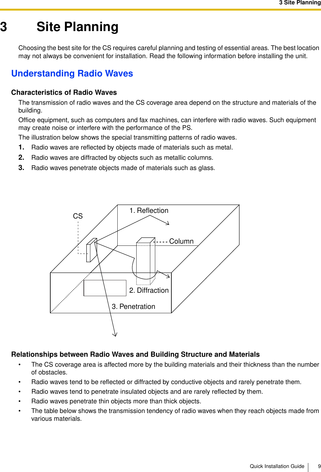
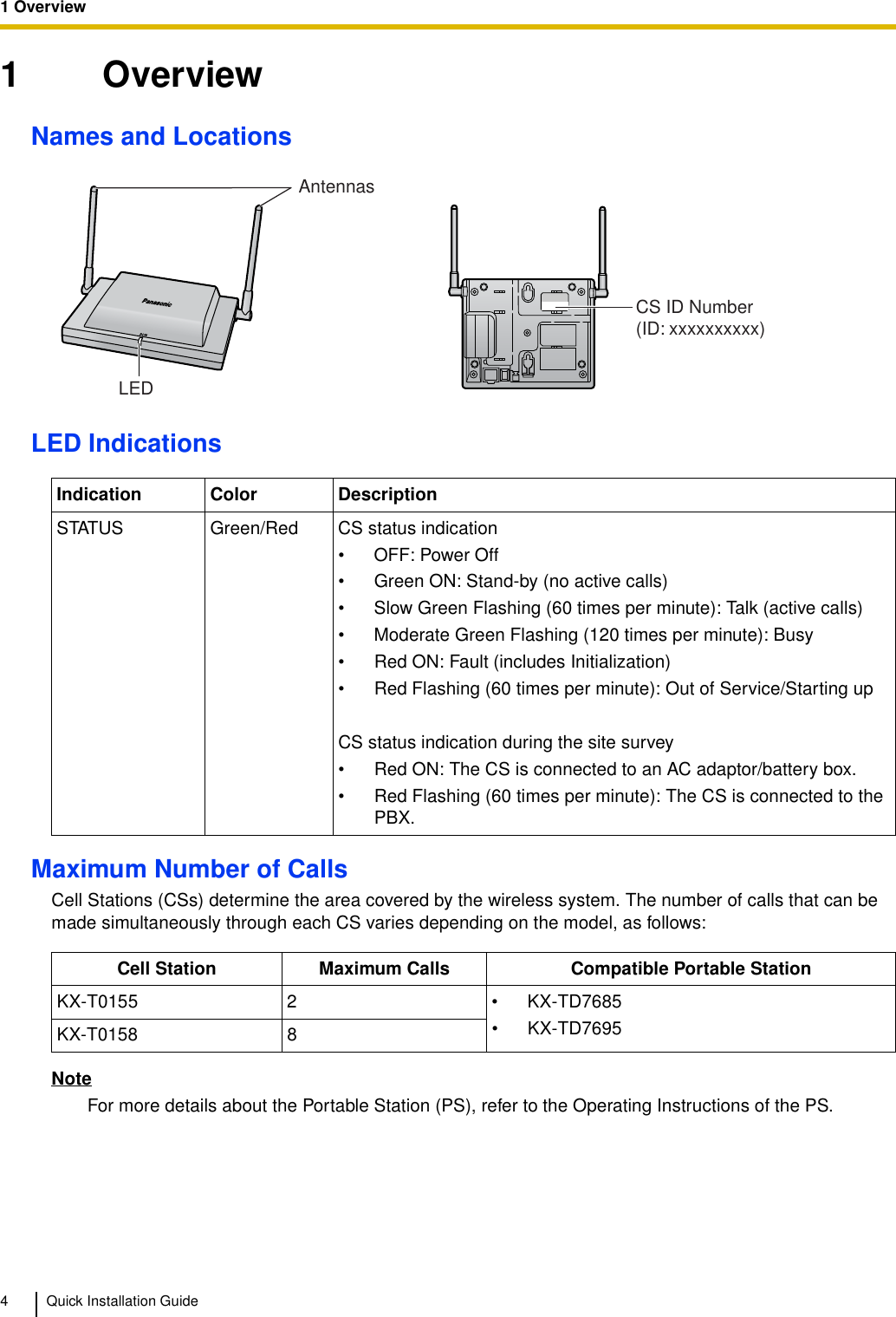
![3 Site PlanningQuick Installation Guide 11CS Coverage AreaThe example below shows the size of the coverage area of 1 CS if it is installed in an area with no obstacles.NoteRadio signal strength levels are measured during the site survey (refer to "5 Site Survey").Site Survey Preparation1. Obtain a map and investigate the installation site.a. Check the obstacles (e.g., shelves, columns, and partitions).b. Check the materials of the structures (e.g., metal, concrete, and plywood).c. Check the layout and dimensions of the room, corridor, etc.d. Write down the above information on the map.2. Examine the service area required by the user on the map, referring to the following example.a. Draw the coverage area around a CS. Extend the coverage area 20 m to 50 m (65 ft to 164 ft) in each direction, depending on the materials of the building structures and obstacles in the installation site. Note that a CS cannot be installed outside a building.b. If 1 CS cannot cover the entire service area, install additional CSs as required. Overlap the coverage areas of adjacent CSs.Where CS coverage areas overlap, the PS will start call handover to the next CS if the signal from ABABCGray Zone:Conversation will be intermittent Out of Service:Cannot make/receive callsGood Coverage AreaRadio signal strengthlevel is greater than "8".(About 20 m to 30 m[65 ft to 98 ft])Good sound qualitycan be maintained.Coverage AreaRadio signal strength level is greater than "3".(About 35 m to 50 m[115 ft to 164 ft])Radio Signal Strength LevelsBetterGoodMay receive noiseReceives noise easily or disconnectsOut of rangeLevel: 11 to 12Level: 08 to 10Level: 03 to 07Level: 01 to 02Level: 00](https://usermanual.wiki/Panasonic-of-North-America/96NKX-T0155/User-Guide-891485-Page-11.png)
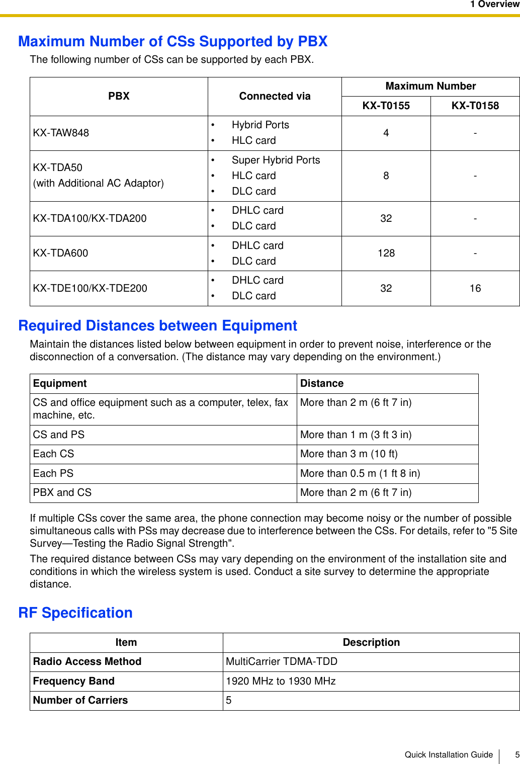
![7 Connecting a Cell Station to the PBXQuick Installation Guide 27Registering the PSThe PS must be registered to the PBX before it can be used. Programming of both the PS and PBX is required. A Proprietary Telephone (PT) with multiline display (e.g., KX-T7636 6-line display) is required to perform the PBX system programming.NoteFor details about system programming using a PT, refer to "PT Programming" in the Feature Manual, and "PT Programming" in the PT Programming Manual for your PBX.Entering the System Programming ModePT (Administrator Level)Note means default value throughout this section.Setting the Personal Identification Number (PIN) for PS RegistrationTo prevent registering the PS to a wrong PBX, a PIN for PS registration can be set to the PBX. Before registering the PS to the PBX, enter the PIN set to the PBX into the PS. By doing so, the PS will only be registered to the PBX with the matching PIN.Notes• By default, the PIN for PS registration is "1234" for both the PBX and PS. Therefore, the PS can be registered to the PBX without setting the PIN.• The PIN for PS registration will only be used when registering the PS to the PBX. Therefore, during normal operation after registration, even if there is more than 1 PBX with the same PIN near the PS, the PS will not be inadvertently linked to a different PBX.Setting the PIN for PBX#1234System Password for Administrator—for PT Programming Programming No.3 digitsPROGRAM/PAUSE[692]4 digitsPIN for PS RegistrationEND(HOLD)ENTER ENTER1234](https://usermanual.wiki/Panasonic-of-North-America/96NKX-T0155/User-Guide-891485-Page-27.png)
![7 Connecting a Cell Station to the PBX28 Quick Installation GuideSetting the PIN for PSUsing the KX-TD7685/KX-TD7695PS RegistrationWhen the PS has not been registered yetWhen registering the PS for the first time, it is possible to select the desired language for the display. (You do not need to enter the PS system programming mode when registering for the first time.)Using the KX-TD7685/KX-TD7695When the PS has already been registered to another PBXOne PS can be registered to a maximum of 4 different PBXs.Using the KX-TD7685/KX-TD7695Select "Change PIN".1 to 8 digits1234C.TonePIN for PS RegistrationPress POWERfor 2 seconds. Select "Setting Handset". Select "System Option".If required4 digitsSystem Lock Password[690]001 to 128PS No.1 to 4 digits END(HOLD)ENTER ENTERTo the PSoperationbelowExtn. No.Press POWER for 2 seconds.Select the desired language.Press "F" for 2 seconds.C.Tone C.ToneIf requiredSelect the desiredbase (Base 1–4).Select "Register H/S".C.TonePress POWERfor 2 seconds. Select "Setting Handset". Select "System Option".If required4 digitsSystem Lock Password](https://usermanual.wiki/Panasonic-of-North-America/96NKX-T0155/User-Guide-891485-Page-28.png)
![7 Connecting a Cell Station to the PBXQuick Installation Guide 29PS TerminationConfirm the following before canceling the PS registration:• The PS is turned on.• The PS is within range.If "Rejected" or "Time out" is displayedThe registration information is still stored in the PS. You need to delete the registration information from the PS.Using the KX-TD7685/KX-TD7695Testing the OperationWalk around the service area while having a conversation using a registered PS. If noise is frequent or conversations disconnect, relocate the CSs or install an additional CS.[691]001 to 128PS No.ENTER ENTEREND(HOLD)If "Rejected" or "Time out" is displayedCLEAR YESPress "YES".Press "CLEAR".Select the desiredbase (Base 1–4).Select "Yes".C.ToneSelect "Cancel Base".Press POWERfor 2 seconds. Select "Setting Handset". Select "System Option".If required4 digitsSystem Lock Password](https://usermanual.wiki/Panasonic-of-North-America/96NKX-T0155/User-Guide-891485-Page-29.png)
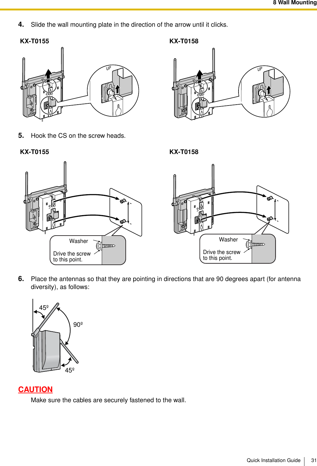
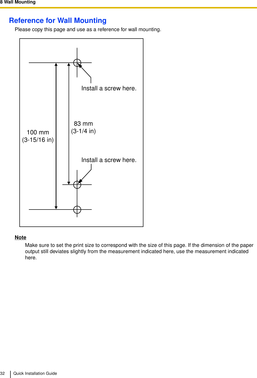
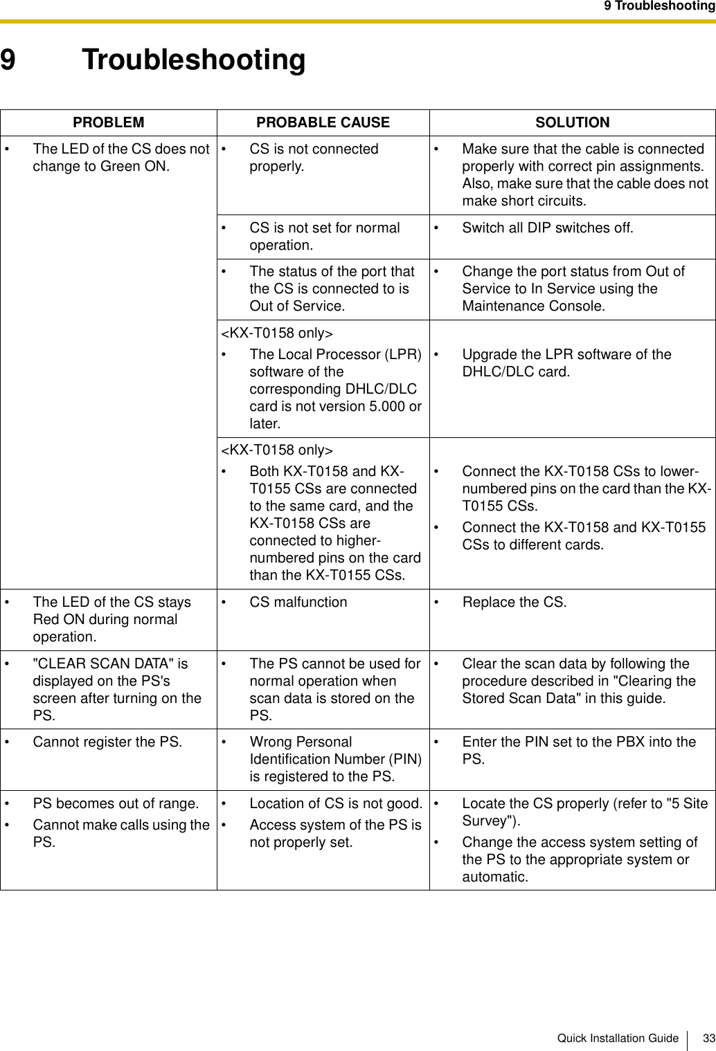
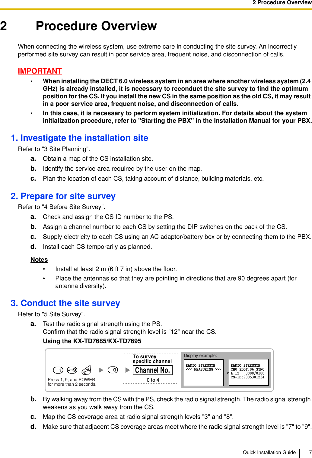
![8 Wall Mounting30 Quick Installation Guide8 Wall MountingMounting the KX-T0155/KX-T0158WARNING• MAKE SURE THAT THE WALL THAT THE UNIT WILL BE ATTACHED TO IS STRONG ENOUGH TO SUPPORT THE UNIT (APPROX. 310 g [11 oz]). IF NOT, IT IS NECESSARY FOR THE WALL TO BE REINFORCED.• ONLY USE THE WALL-MOUNTING EQUIPMENT (SCREWS, WASHERS, WALL MOUNTING PLATE) INCLUDED WITH THE UNIT.• WHEN DRIVING THE SCREWS INTO THE WALL, BE CAREFUL TO AVOID TOUCHING ANY METAL LATHS, WIRE LATHS OR METAL PLATES IN THE WALL.• WHEN THIS PRODUCT IS NO LONGER IN USE, MAKE SURE TO DETACH IT FROM THE WALL.1. Place the reference for wall mounting on the wall to mark the 2 screw positions.2. Install the 2 screws and washers (included) into the wall.Notes• Make sure that the screw heads are at the same distance from the wall.• Install the screws perpendicular to the wall.3. Insert the upper and lower tabs of the wall mounting plate into the designated openings in the base unit.KX-T0155 KX-T0158TabsWall Mounting Plate (PSKL1032Y4)TabsWall Mounting Plate (PSKL1032Y4)](https://usermanual.wiki/Panasonic-of-North-America/96NKX-T0155/User-Guide-891485-Page-30.png)