Panasonic of North America 96NKX-T0158 Isochronous UPCS Cell Station (Base) User Manual QuickInstallationGuide
Panasonic Corporation of North America Isochronous UPCS Cell Station (Base) QuickInstallationGuide
User Manual
Model No.
KX-T0155/KX-T0158
DECT 6.0 Cell Station Unit
Quick Installation Guide
Document Version: 2008-01
Thank you for purchasing a Panasonic DECT 6.0 Cell Station Unit.
Please read this manual carefully before using this product and save this manual for future use.

2 Quick Installation Guide
F.C.C. REQUIREMENTS AND RELEVANT
INFORMATION
Privacy of communications may not be ensured when using the wireless systems.
CAUTION
Any changes or modifications not expressly approved by the party responsible for compliance could
void the user's authority to operate this device.
Note
This equipment has been tested and found to comply with the limits for a Class B digital device,
pursuant to Part 15 of the FCC Rules. These limits are designed to provide reasonable protection
against harmful interference in a residential installation. This equipment generates, uses, and can
radiate radio frequency energy and, if not installed and used in accordance with the instructions, may
cause harmful interference to radio communications. However, there is no guarantee that interference
will not occur in a particular installation. If this equipment does cause harmful interference to radio or
television reception, which can be determined by turning the equipment off and on, the user is
encouraged to try to correct the interference by one or more of the following measures:
• Reorient or relocate the receiving antenna.
• Increase the distance between the equipment and receiver.
• Connect the equipment to an outlet on a circuit different from that to which the receiver is
connected.
• Consult the dealer or an experienced radio/TV technician for help.
Some wireless telephones operate at frequencies that may cause interference to nearby TVs and
VCRs. To minimize or prevent such interference, the base of the wireless telephone should not be
placed near or on top of a TV or VCR. If interference is experienced, move the wireless telephone
further away from the TV or VCR. This will often reduce, or eliminate, interference.
CAUTION
To comply with FCC RF exposure requirements in an uncontrolled environment:
• This equipment must be installed and operated in accordance with provided instructions and a
minimum 20 cm (8 in) spacing must be provided between antenna and all person's body (excluding
extremities of hands, wrist and feet) during wireless modes of operation.
• This transmitter must not be co-located or operated in conjunction with any other antenna or
transmitter.
Medical—consult the manufacturer of any personal medical devices, such as pacemakers, to
determine if they are adequately shielded from external RF (radio frequency) energy. (The unit operates
in the frequency range of 1920 MHz to 1930 MHz, and the output peak power level is less than 0.12
W.) Do not use the unit in health care facilities if any regulations posted in the area instruct you not to
do so. Hospitals or health care facilities may be using equipment that could be sensitive to external RF
(radio frequency) energy.

Quick Installation Guide 3
Table of Contents
1 Overview..................................................................................................4
2 Procedure Overview...............................................................................7
3 Site Planning...........................................................................................9
4 Before Site Survey................................................................................13
5 Site Survey ............................................................................................18
6 After Site Survey...................................................................................22
7 Connecting a Cell Station to the PBX.................................................23
8 Wall Mounting .......................................................................................30
9 Troubleshooting....................................................................................33
1 Overview
4 Quick Installation Guide
1Overview
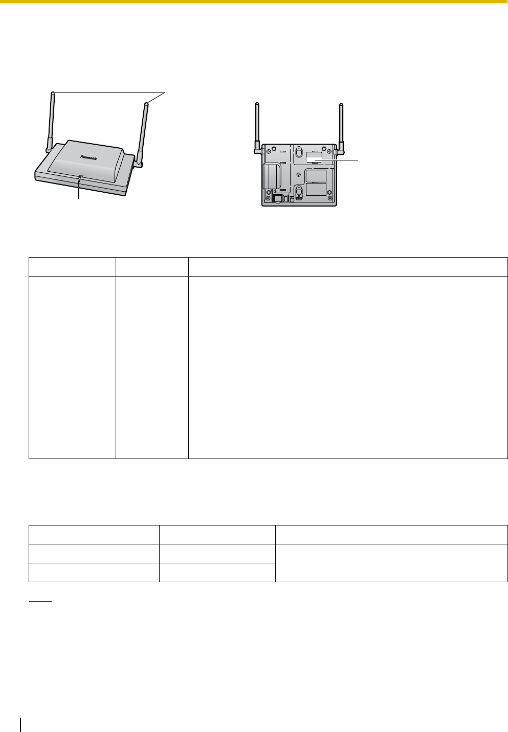
Names and Locations
LED Indications
Maximum Number of Calls
Cell Stations (CSs) determine the area covered by the wireless system. The number of calls that can be
made simultaneously through each CS varies depending on the model, as follows:
Note
For more details about the Portable Station (PS), refer to the Operating Instructions of the PS.
Indication Color Description
STATUS Green/Red CS status indication
• OFF: Power Off
• Green ON: Stand-by (no active calls)
• Slow Green Flashing (60 times per minute): Talk (active calls)
• Moderate Green Flashing (120 times per minute): Busy
• Red ON: Fault (includes Initialization)
• Red Flashing (60 times per minute): Out of Service/Starting up
CS status indication during the site survey
• Red ON: The CS is connected to an AC adaptor/battery box.
• Red Flashing (60 times per minute): The CS is connected to the
PBX.
Cell Station Maximum Calls Compatible Portable Station
KX-T0155 2 • KX-TD7685
• KX-TD7695
KX-T0158 8
LED
Antennas
CS ID Number
(ID: xxxxxxxxxx)
1 Overview
Quick Installation Guide 5
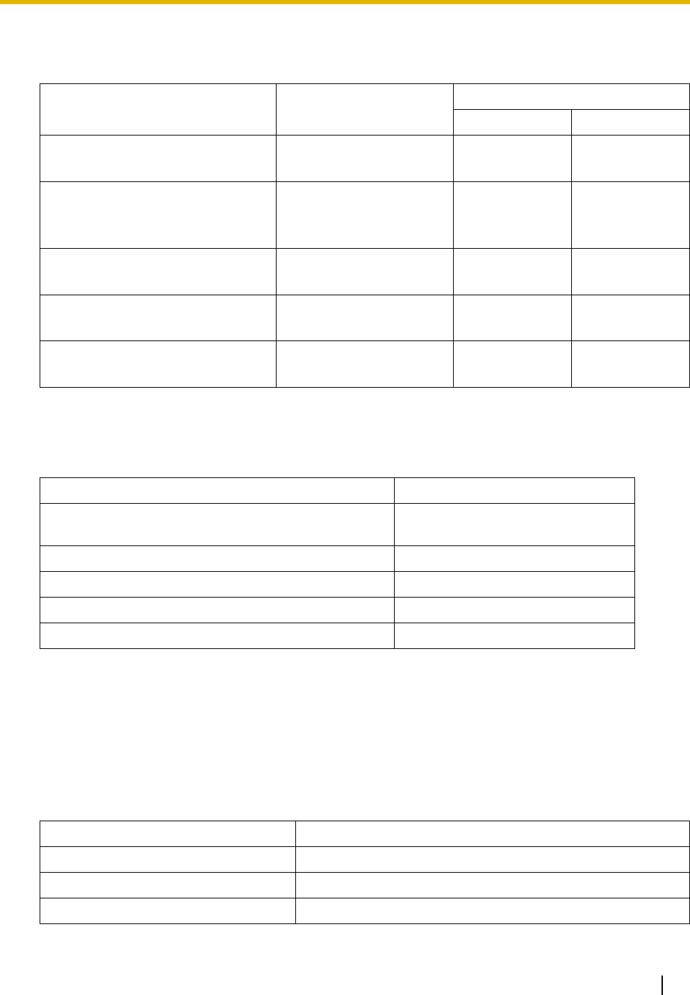
Maximum Number of CSs Supported by PBX
The following number of CSs can be supported by each PBX.
Required Distances between Equipment
Maintain the distances listed below between equipment in order to prevent noise, interference or the
disconnection of a conversation. (The distance may vary depending on the environment.)
If multiple CSs cover the same area, the phone connection may become noisy or the number of possible
simultaneous calls with PSs may decrease due to interference between the CSs. For details, refer to "5 Site
Survey—Testing the Radio Signal Strength".
The required distance between CSs may vary depending on the environment of the installation site and
conditions in which the wireless system is used. Conduct a site survey to determine the appropriate
distance.
RF Specification
PBX Connected via Maximum Number
KX-T0155 KX-T0158
KX-TAW848 •Hybrid Ports
•HLC card 4-
KX-TDA50
(with Additional AC Adaptor)
• Super Hybrid Ports
•HLC card
•DLC card
8-
KX-TDA100/KX-TDA200 • DHLC card
•DLC card 32 -
KX-TDA600 • DHLC card
•DLC card 128 -
KX-TDE100/KX-TDE200 • DHLC card
•DLC card 32 16
Equipment Distance
CS and office equipment such as a computer, telex, fax
machine, etc. More than 2 m (6 ft 7 in)
CS and PS More than 1 m (3 ft 3 in)
Each CS More than 3 m (10 ft)
Each PS More than 0.5 m (1 ft 8 in)
PBX and CS More than 2 m (6 ft 7 in)
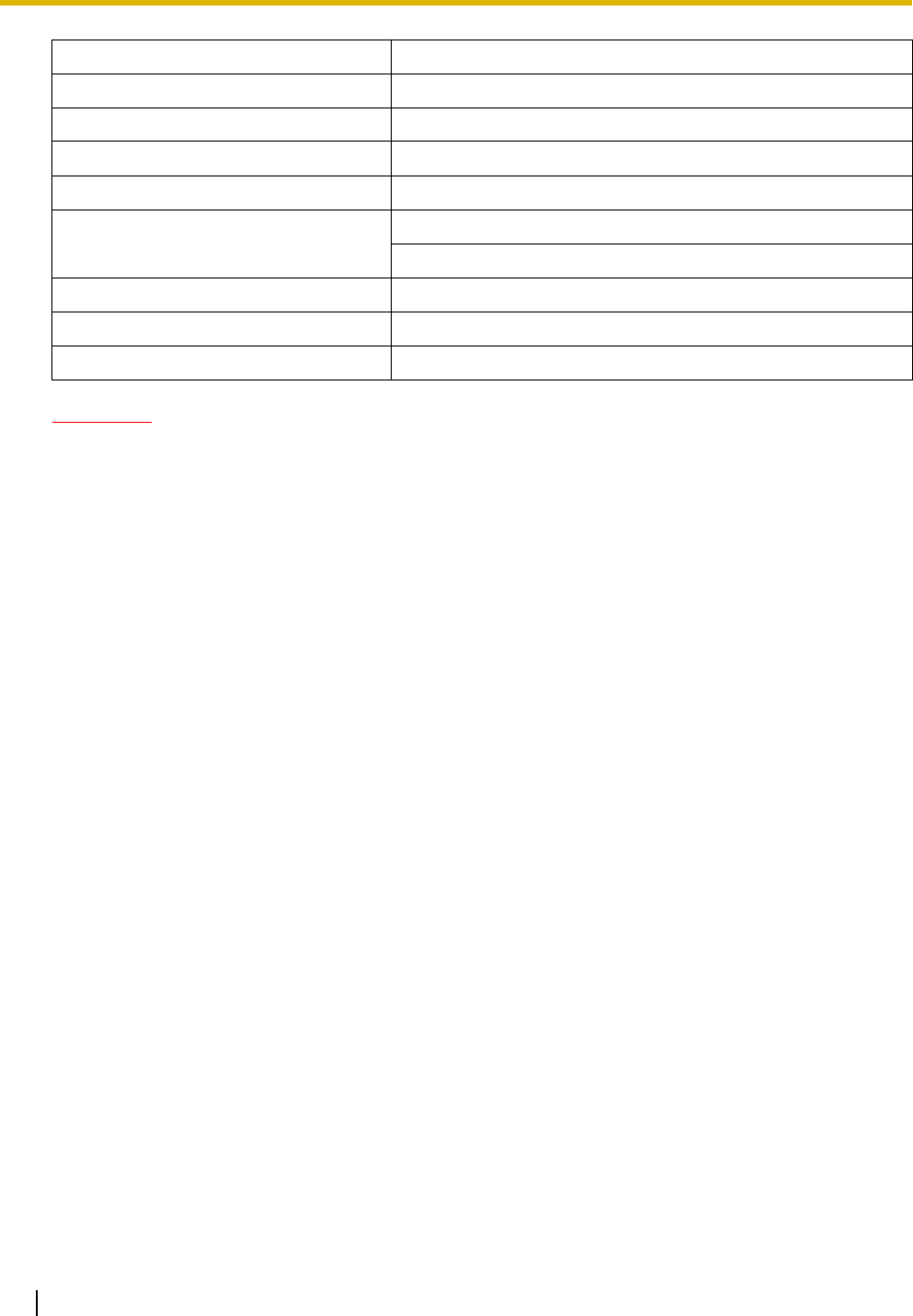
Item Description
Radio Access Method MultiCarrier TDMA-TDD
Frequency Band 1920 MHz to 1930 MHz
Number of Carriers 5
1 Overview
6 Quick Installation Guide
CAUTION
• The CS should be kept free of dust, moisture, high temperature (more than 40 °C [104 °F]), low
temperature (less than 0 °C [32 °F]), and vibration, and should not be exposed to direct sunlight.
• The CS should not be placed outdoors (use indoors).
• The CS should not be placed near high-voltage equipment.
• The CS should not be placed on a metal object.
Carrier Spacing 1728 kHz
Bit Rate 1152 kbps
Carrier Multiplex TDMA, 24 (Tx12, Rx12) slots per frame
Frame Length 10 ms
Modulation Scheme GFSK
Roll-off factor=0.5 50 % roll-off in the transmitter
Data Coding for Modulator Differential Coding
Voice CODEC 32 kbps ADPCM (CCITT G.726)
Transmission Output Peak 125 mW
Item Description
2 Procedure Overview
Quick Installation Guide 7
2 Procedure Overview
When connecting the wireless system, use extreme care in conducting the site survey. An incorrectly
performed site survey can result in poor service area, frequent noise, and disconnection of calls.
IMPORTANT
• When installing the DECT 6.0 wireless system in an area where another wireless system (2.4
GHz) is already installed, it is necessary to reconduct the site survey to find the optimum
position for the CS. If you install the new CS in the same position as the old CS, it may result
in a poor service area, frequent noise, and disconnection of calls.
• In this case, it is necessary to perform system initialization. For details about the system
initialization procedure, refer to "Starting the PBX" in the Installation Manual for your PBX.
1. Investigate the installation site
Refer to "3 Site Planning".
a. Obtain a map of the CS installation site.
b. Identify the service area required by the user on the map.
c. Plan the location of each CS, taking account of distance, building materials, etc.
2. Prepare for site survey
Refer to "4 Before Site Survey".
a. Check and assign the CS ID number to the PS.
b. Assign a channel number to each CS by setting the DIP switches on the back of the CS.
c. Supply electricity to each CS using an AC adaptor/battery box or by connecting them to the PBX.
d. Install each CS temporarily as planned.
Notes
• Install at least 2 m (6 ft 7 in) above the floor.
• Place the antennas so that they are pointing in directions that are 90 degrees apart (for
antenna diversity).
3. Conduct the site survey
Refer to "5 Site Survey".
a. Test the radio signal strength using the PS.
Confirm that the radio signal strength level is "12" near the CS.
Using the KX-TD7685/KX-TD7695
b. By walking away from the CS with the PS, check the radio signal strength. The radio signal strength
weakens as you walk away from the CS.
c. Map the CS coverage area at radio signal strength levels "3" and "8".
d. Make sure that adjacent CS coverage areas meet where the radio signal strength level is "7" to "9".
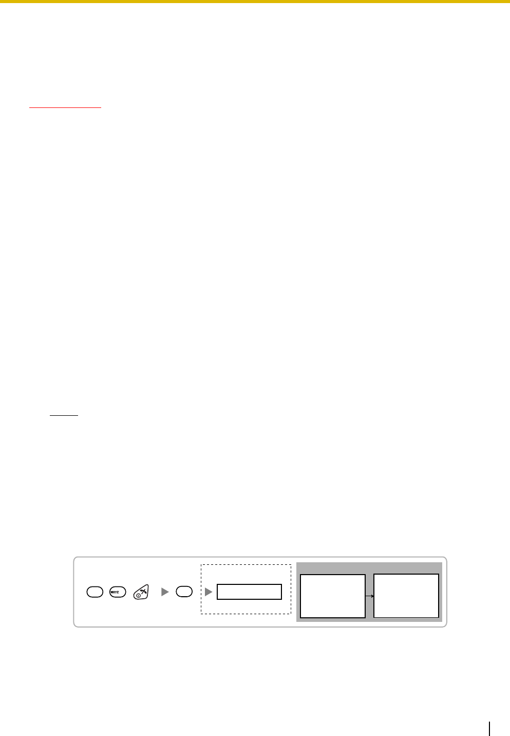
Display example:
RADIO STRENGTH
<<< MEASURING >>> RADIO STRENGTH
CH0 SLOT:06 SYNC
L:12 0000/0100
CS-ID:9005301234
Press 1, 9, and POWER
for more than 2 seconds.
199
0
0 to 4
Channel No.
To survey
specific channel

2 Procedure Overview
8 Quick Installation Guide
e. Make sure that the radio signal strength level is greater than "3" at any location within the service
area required by the user.
4. Finish the site survey
Refer to "6 After Site Survey".
a. Turn off the PS.
b. Stop supplying power, and return all DIP switches of each CS to the OFF position.
5. Connect the CS and PS to the PBX and test the operation
Refer to "7 Connecting a Cell Station to the PBX".
a. Connect the CSs to the PBX.
b. Register the PSs to the PBX.
c. Walk around the service area while having a conversation using a registered PS. If noise is
frequent or conversations disconnect, relocate the CSs or install an additional CS.
6. Mount the CS on the wall
Refer to "8 Wall Mounting".
a. If there are no problems in testing, mount the CS on the wall.
3 Site Planning
Quick Installation Guide 9
3 Site Planning
Choosing the best site for the CS requires careful planning and testing of essential areas. The best location
may not always be convenient for installation. Read the following information before installing the unit.
Understanding Radio Waves
Characteristics of Radio Waves
The transmission of radio waves and the CS coverage area depend on the structure and materials of the
building.
Office equipment, such as computers and fax machines, can interfere with radio waves. Such equipment
may create noise or interfere with the performance of the PS.
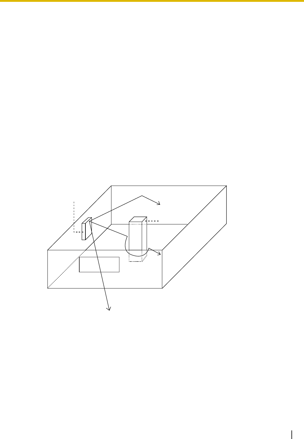
The illustration below shows the special transmitting patterns of radio waves.
1. Radio waves are reflected by objects made of materials such as metal.
2. Radio waves are diffracted by objects such as metallic columns.
3. Radio waves penetrate objects made of materials such as glass.
Relationships between Radio Waves and Building Structure and Materials
• The CS coverage area is affected more by the building materials and their thickness than the number
of obstacles.
• Radio waves tend to be reflected or diffracted by conductive objects and rarely penetrate them.
• Radio waves tend to penetrate insulated objects and are rarely reflected by them.
• Radio waves penetrate thin objects more than thick objects.
• The table below shows the transmission tendency of radio waves when they reach objects made from
various materials.
CS
Column
3. Penetration
2. Diffraction
1. Reflection
3 Site Planning
10 Quick Installation Guide
Object Material Transmission Tendency
Wall Concrete The thicker they are, the less radio waves
penetrate them.
Ferroconcrete Radio waves can penetrate them, but the more iron
there is, the more radio waves are reflected.
Window Glass Radio waves usually penetrate them.
Glass with wire net Radio waves can penetrate them, but tend to be
reflected.
Glass covered with heat-
resistant film Radio waves are weakened considerably when
they penetrate windows.
Floor Ferroconcrete Radio waves can penetrate them, but the more iron
there is, the more radio waves are reflected.
Partition Steel Radio waves are reflected and rarely penetrate
them.
Plywood, Glass Radio waves usually penetrate them.
Column Ferroconcrete Radio waves can penetrate them, but the more iron
there is, the more radio waves tend to be reflected
or diffracted.
Metal Radio waves tend to be reflected or diffracted.
Cabinet Steel Radio waves are usually reflected or diffracted,
and rarely penetrate them.
Wood Radio waves can penetrate them, but they are
weakened.
3 Site Planning
Quick Installation Guide 11
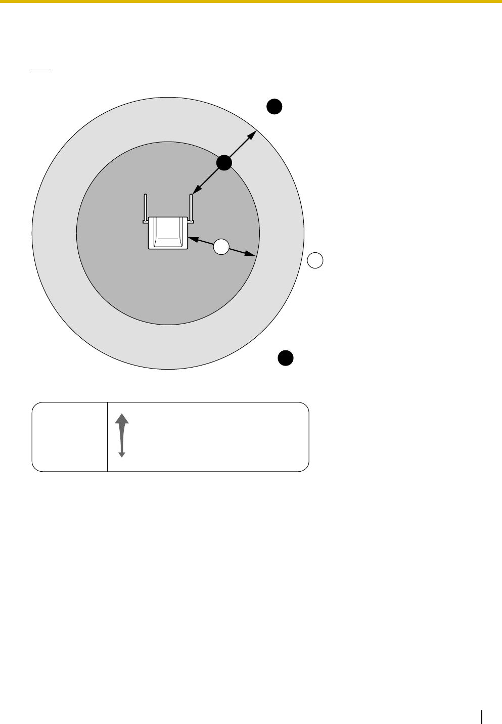
CS Coverage Area
The example below shows the size of the coverage area of 1 CS if it is installed in an area with no obstacles.
Note
Radio signal strength levels are measured during the site survey (refer to "5 Site Survey").
Site Survey Preparation
1. Obtain a map and investigate the installation site.
a. Check the obstacles (e.g., shelves, columns, and partitions).
b. Check the materials of the structures (e.g., metal, concrete, and plywood).
c. Check the layout and dimensions of the room, corridor, etc.
d. Write down the above information on the map.
2. Examine the service area required by the user on the map, referring to the following example.
a. Draw the coverage area around a CS. Extend the coverage area 20 m to 50 m (65 ft to 164 ft) in
each direction, depending on the materials of the building structures and obstacles in the
installation site. Note that a CS cannot be installed outside a building.
b. If 1 CS cannot cover the entire service area, install additional CSs as required. Overlap the
coverage areas of adjacent CSs.
Where CS coverage areas overlap, the PS will start call handover to the next CS if the signal from
A
B
A
B
C
Gray Zone:
Conversation will be
intermittent Out of Service:
Cannot make/receive calls
Good Coverage Area
Radio signal strength
level is greater than "8".
(About 20 m to 30 m
[65 ft to 98 ft])
Good sound quality
can be maintained.
Coverage Area
Radio signal strength level is
greater than "3".
(About 35 m to 50 m
[115 ft to 164 ft])
Radio Signal Strength Levels
Better
Good
May receive noise
Receives noise easily or disconnects
Out of range
Level: 11 to 12
Level: 08 to 10
Level: 03 to 07
Level: 01 to 02
Level: 00
3 Site Planning
12 Quick Installation Guide
one CS becomes weak. However, if a PS moves away from a CS and there are no CSs available
for handover, the PS may go out of range and the call could be lost.
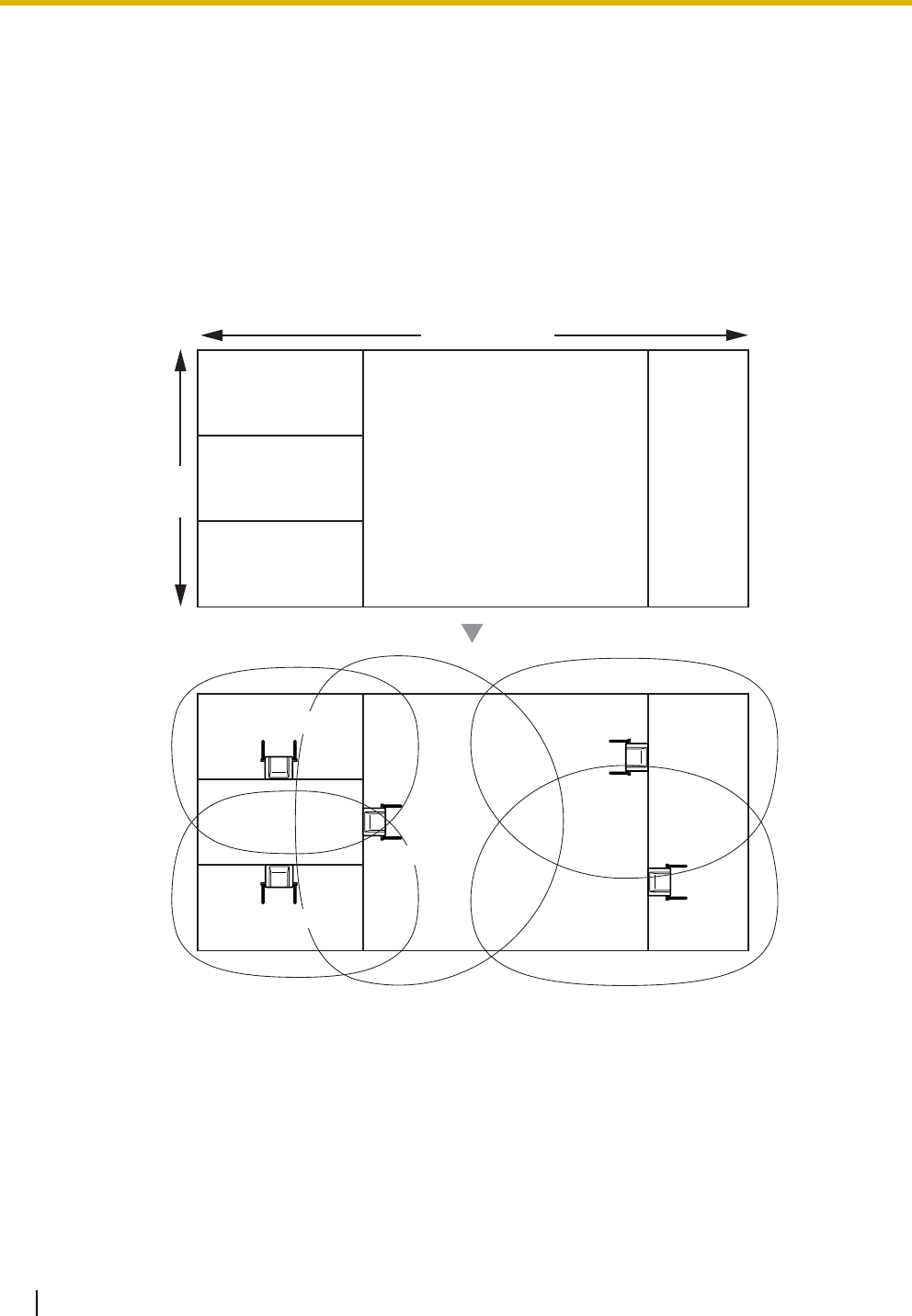
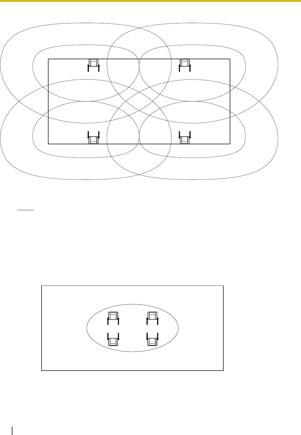
Example: Installing in a Room Separated by Interior Walls
Things to take note of:
• The room is separated by interior walls.
• The room is surrounded by concrete walls.
CS installation plan:
• The coverage area of each CS will not extend as far as when there are no obstacles, because the
radio signals will be weakened by separating walls. Therefore, you will need 5 CSs to cover the
entire room.
100 m (328 ft)
50 m
(164 ft)
CS no. 1
CS no. 2
CS no. 4
CS no. 5
CS no. 3
4 Before Site Survey
Quick Installation Guide 13
4 Before Site Survey
Use the KX-TD7685/KX-TD7695 PS to conduct the site survey.
Note
Display prompts for the site survey are only available in English.
Checking the CS ID Number
Check the CS ID number label attached to the CS. If the CS ID number label is not attached to the CS, check
the CS ID number using the Maintenance Console. For details, refer to "Utility—CS Information" in the PC
Programming Manual for your PBX.
Assigning the CS ID Number to the PS
Using the KX-TD7685/KX-TD7695
Note
To clear the CS ID number assigned to the PS, follow the procedure below:
Press 1, 9, and POWER
for more than 2 seconds. 0 to 7 0 to 9 and A to F
CS No. CS ID No.
199
2
ABC
To enter letters
A: + C: + E: +
B: + D: + F: +
To the initial display To the Desired CS No.
3
DEF
4
GHI
0
15
JKL
2
ABC
Press 1, 9, and POWER
for more than 2 seconds.
0 to 7
CS No.
199
3
DEF
To the Desired CS No.
OR
#
To clear one by one
To clear all at once
To the initial display
4 Before Site Survey
14 Quick Installation Guide
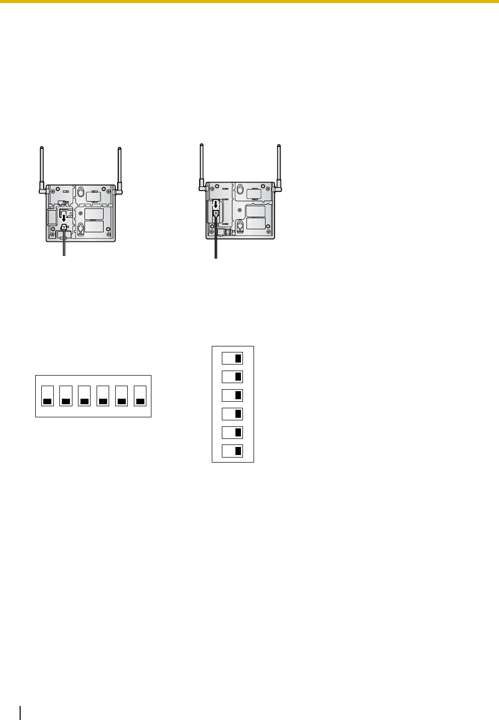
Setting and Installing the CS Temporarily for Site Survey
1. Switch the Radio Signal Test switch from OFF to ON.
2. Set the channel number switches as desired.
3. Set the Power Supply Select switch as desired.
KX-T0155
12345 6
4
4
4
4
3
3
3
3
2
2
2
2
1
1
1
1
4321
Channel 1
Channel 0
Channel 2
Channel 3
Channel 4
DIP Switch
Radio Signal Test Switch
Power Supply Select Switch
Channel Number Switch
OFF
ON
ON: From the AC Adaptor (KX-A11/KX-TCA1/
PSLP1434Y)/Battery Box (PSZZTD142CE)
OFF: From the PBX
4 Before Site Survey
Quick Installation Guide 15
KX-T0158
Note
If more than 1 CS is in Radio Signal Test mode, each CS must have a unique channel number.
6
5
4
3
2
1
4
3
2
1
4
3
2
1
4
3
2
1
4
3
2
1
4
3
2
1
DIP Switch
Radio Signal Test Switch
Power Supply Select Switch
Channel Number Switch
Channel 1 Channel 2 Channel 3 Channel 4Channel 0
ON OFF
ON: From the AC Adaptor (KX-A11/PSLP1434Y)/
Battery Box (PSZZTD142CE)
OFF: From the PBX
4 Before Site Survey
16 Quick Installation Guide
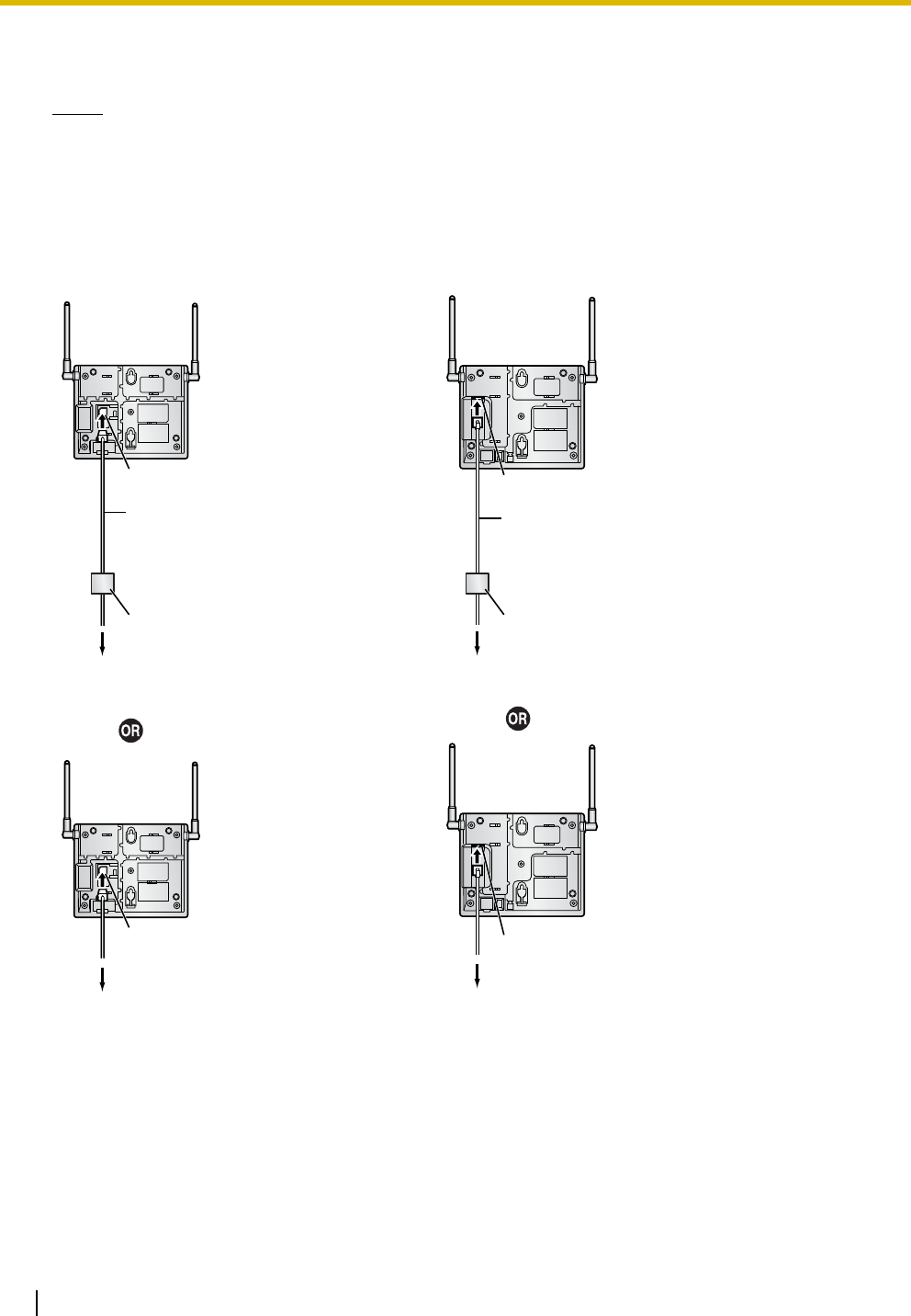
4. After setting the DIP switches, connect the CS to an AC adaptor/battery box using a power supply
adaptor, or connect it to the PBX.
Notes
• The AC adaptor should be connected to a vertically oriented or floor-mounted AC outlet. Do not
connect the AC adaptor to a ceiling-mounted AC outlet, as the weight of the adaptor may cause it
to become disconnected.
• If the Power Supply Select switch is set to ON in step 3, connect the CS to an AC adaptor/battery
box. If it is set to OFF, connect the CS to the PBX.
KX-T0155 KX-T0158
To AC Adaptor (KX-A11/KX-TCA1/PSLP1434Y)/
Battery Box (PSZZTD142CE)
Power Supply Adaptor
(PSZZ1TDA0142)
RJ11 Modular
RJ11 Modular
Telephone Cord
To PBX
RJ11 Modular
RJ45 Modular
To AC Adaptor (KX-A11/PSLP1434Y)/
Battery Box (PSZZTD142CE)
To PBX
Power Supply Adaptor
(PSZZ1TDA0142)
RJ45 Modular
Telephone Cord
(PSJA1017Z)
RJ11 Modular
4 Before Site Survey
Quick Installation Guide 17
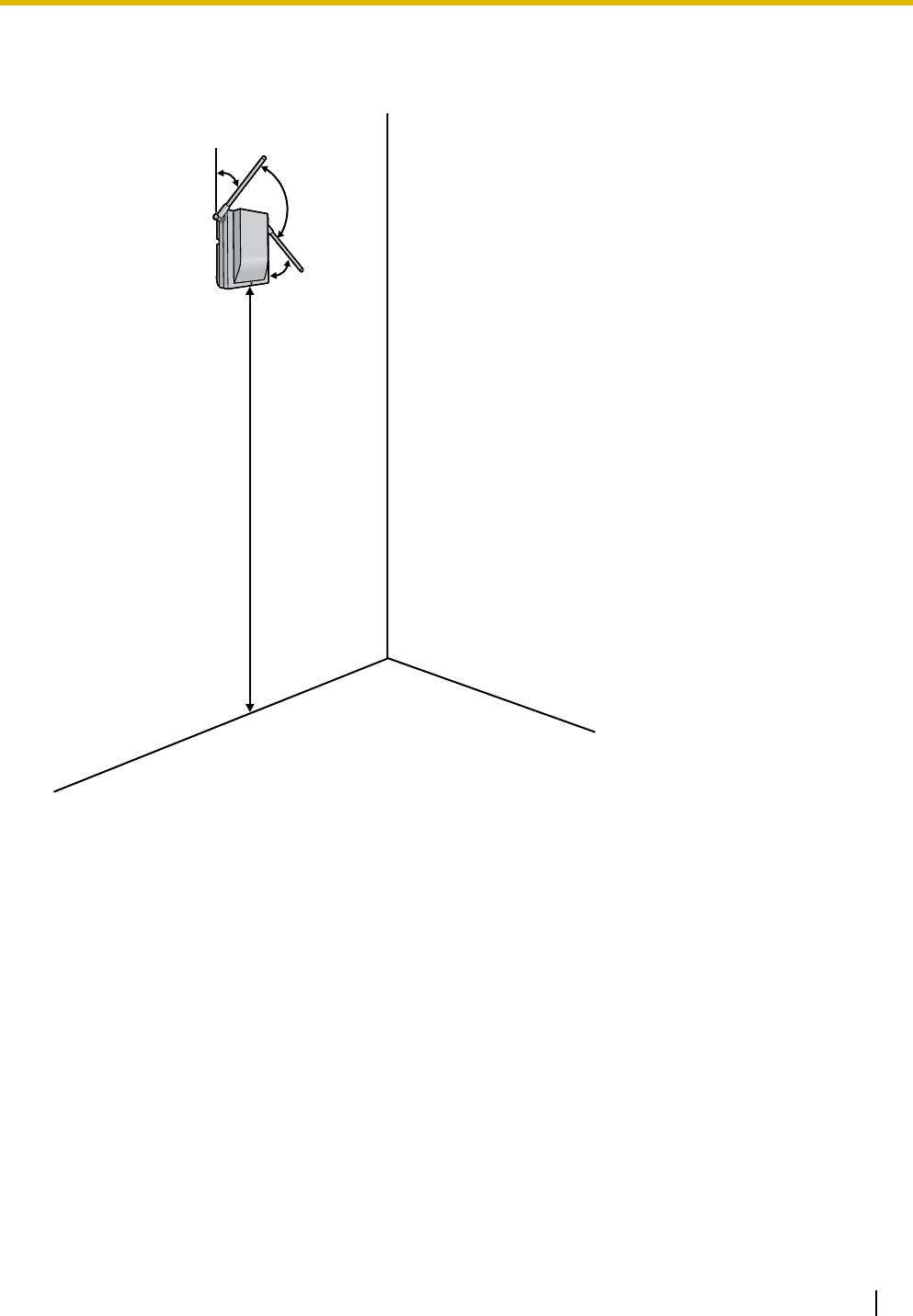
5. Install the CS temporarily for the site survey. Install the CS at least 2 m (6 ft 7 in) above the floor, and
place the antennas so that they are pointing in directions that are 90 degrees apart (for antenna
diversity), as follows:
At least 2 m
(6 ft 7 in)
45º
45º
90º
5 Site Survey
18 Quick Installation Guide
5Site Survey
The PS has a Radio Signal Test mode that monitors the state of the radio link to the CS for site survey. In
Radio Signal Test mode, the frame loss and signal strength of a synchronous slot, and the signal strength
of the other slots can be measured when the PS is monitoring the CS. After installing the CSs temporarily
as planned during site planning, set the PS to Radio Signal Test mode and locate each CS to measure its
coverage area. Then, record the results on the map of the installation site.
Testing the Radio Signal Strength
After locating the CS(s) temporarily, execute the Radio Signal Test using the PS. Directly after entering
Radio Signal Test mode, the PS scans channel 0 for a CS that it can connect to. The channel to be scanned
can be changed by pressing the appropriate keys 0 through 4.
1. Enter Radio Signal Test mode.
Using the KX-TD7685/KX-TD7695
Notes
*1: Channel number
*2: Slot number
*3: When a slot is synchronized, "SYNC" is displayed.
*4: Radio signal strength level (12 to 00)
*5: Frame error (0000 to 9999)/Frame counter (0000 to 9999). Frame error indicates the number of
errors out of 10 000 radio signal receptions. An increased number of frame errors indicates greater
radio signal interference and more frequent noise during conversation. The ideal number of frame
errors is "0000".
CAUTION
• Storing the scan data will clear all directory data.
• The PS will not operate in normal mode if scan data is saved on it. For details on clearing scan
data, refer to "Clearing the Stored Scan Data".
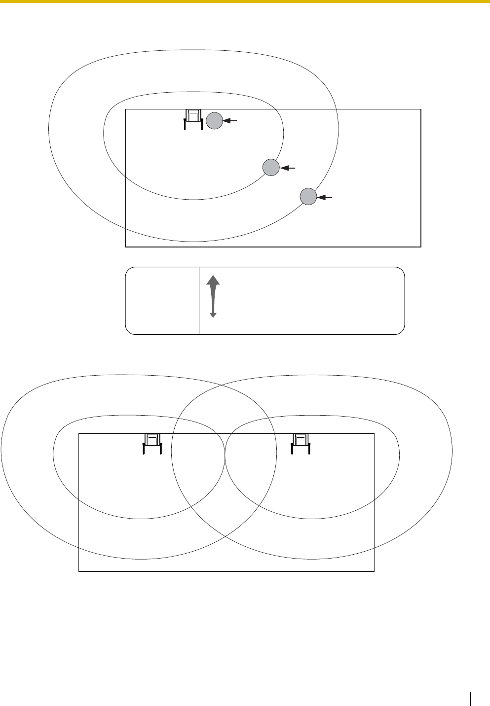
2. Measure the radio signal strength by moving towards and away from the CS.
a. Move to the CS until the radio signal strength level becomes "12".
b. Move away from the CS and identify the CS coverage area within which the radio signal strength
level is greater than "8". Draw the area on the map.
0 to 9
Log No.
To store the scan data
Press 1, 9, and POWER
for more than 2 seconds.
199
Previous or Next 0 to 4
Channel No.
To survey other slots To survey specific channel
/
RADIO STRENGTH
<<< MEASURING >>> RADIO STRENGTH
CH0
*1
SLOT:06
*2
SYNC
*3
L:12
*4
0000/0100
*5
CS-ID:9005301234
0
Display example:
5 Site Survey
Quick Installation Guide 19
c. Move away from the CS and identify the CS coverage area within which the radio signal strength
level is greater than "3". Draw the area on the map.
3. Repeat steps 1 and 2 for other CSs, and relocate the CSs when necessary.
a. Plan adjacent CS coverage areas so that areas meet where radio signal strength level is "7" to "9".
PS
PS
PS
Channel no. 0
CH0
L:03
CH0
L:12
Radio Signal Strength Levels
Better
Good
May receive noise
Receives noise easily or disconnects
Out of range
Level: 11 to 12
Level: 08 to 10
Level: 03 to 07
Level: 01 to 02
Level: 00
CH0
L:08
Channel no. 0 Channel no. 1
5 Site Survey
20 Quick Installation Guide
b. Plan the CS coverage areas to meet for at least 2 CSs at any location in the installation site.
c. Make sure that the radio signal strength level is greater than "3" at any location in the service area
required by the user.
Notes
• If a channel is set, the results of measurement for the 24 slots on the channel are saved each time.
If the same channel is set, the new results override the previous ones. Therefore, a measurement
of 5 channels × 24 slots in total can be made.
• If correct results cannot be obtained (e.g., there are many frame errors), change the location of the
CS and repeat the site survey to select the best location.
• If multiple CSs cover the same area, the phone connection may become noisy or the number of
possible simultaneous calls with PSs may decrease due to interference between the CSs. As a
guideline, the maximum number of CSs in an area with a radio signal strength of "11" is 4 (for KX-
T0155)/2 (for the KX-T0158).
To guarantee the number of simultaneous calls, the KX-T0158 is recommended.
Channel no. 0 Channel no. 1
Channel no. 2 Channel no. 3
Level 11
KX-T0155
5 Site Survey
Quick Installation Guide 21
Referring to the Stored Scan Data
Using the KX-TD7685/KX-TD7695
Clearing the Stored Scan Data
Using the KX-TD7685/KX-TD7695
Press 1, 9, and POWER
for more than 2 seconds. 0 to 9
Log No.
19
1
Previous or Next 0 to 4
Channel No.
To go to other slots To go to specific channel
/
A a
Press 1, 9, and POWER
for more than 2 seconds.
19
4
GHI
6 After Site Survey
22 Quick Installation Guide
6 After Site Survey
After obtaining the proper measurement results, exit Radio Signal Test mode before connecting the CS to
the PBX.
1. Hold down the POWER button on the PS until the PS is turned OFF.
2. Disconnect the CS from the AC adaptor/battery box or the PBX to stop supplying electricity.
3. Switch all DIP switches on the CS from ON to OFF.
KX-T0155 KX-T0158
KX-T0155 KX-T0158
12345 6
OFF
ON
6
5
4
3
2
1
ON OFF
7 Connecting a Cell Station to the PBX
Quick Installation Guide 23
7 Connecting a Cell Station to the PBX
Connection Examples for KX-TAW848/KX-TDA50
Refer to the following examples to connect a CS to the PBX.
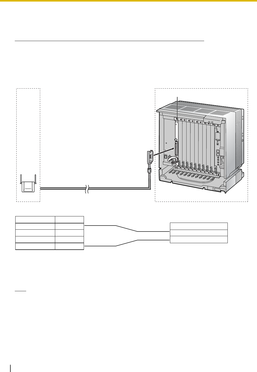
KX-T0155 connecting to KX-TAW848/KX-TDA50
Accessories and User-supplied Items for the CS
Accessories (included): Screws × 2, Washers × 2
User-supplied (not included): RJ11 connector
Note
For details about the Super Hybrid Ports (Hybrid Ports) or HLC4/DLC4/DLC8 card, refer to the
Installation Manual for your PBX.
A Super Hybrid Port (Hybrid Port),
or HLC4/DLC4/DLC8 card (RJ11) CS (RJ11)
Maximum Distance
222 m (728 ft)
347 m (1138 ft)
500 m (1640 ft)
Cable
26 AWG:
24 AWG:
22 AWG:
Signal Name
Signal Name Pin No.
1
2
3
4
D1
D2
D1
D2
Pin No.
1
2
3
4
7 Connecting a Cell Station to the PBX
24 Quick Installation Guide
Connection Examples for KX-TDA100/KX-TDA200/KX-TDA600/KX-
TDE100/KX-TDE200
Note for KX-TDE100/KX-TDE200 (PMMPR Software File Version 1.xxxx) Users
When connecting both KX-T0155 and KX-T0158 CSs to the same card, the KX-T0158 CSs must be
connected to lower-numbered pins on the card than the KX-T0155 CSs.
Refer to the following examples to connect a CS to the PBX.
KX-T0155 connecting to KX-TDA100/KX-TDA200/KX-TDA600/KX-TDE100/KX-TDE200
Accessories and User-supplied Items for the CS
Accessories (included): Screws × 2, Washers × 2
User-supplied (not included): RJ11 connector
Note
For details about the DHLC/DLC card, refer to the Installation Manual for your PBX.
D1
D2
Signal Name
DHLC/DLC card (Amphenol)
1
2
3
4
D1
D2
CS (RJ11)
Pin No.
Signal Name
DHLC8 Card
Maximum Distance
222 m (728 ft)
347 m (1138 ft)
500 m (1640 ft)
Cable
26 AWG:
24 AWG:
22 AWG:
7 Connecting a Cell Station to the PBX
Quick Installation Guide 25
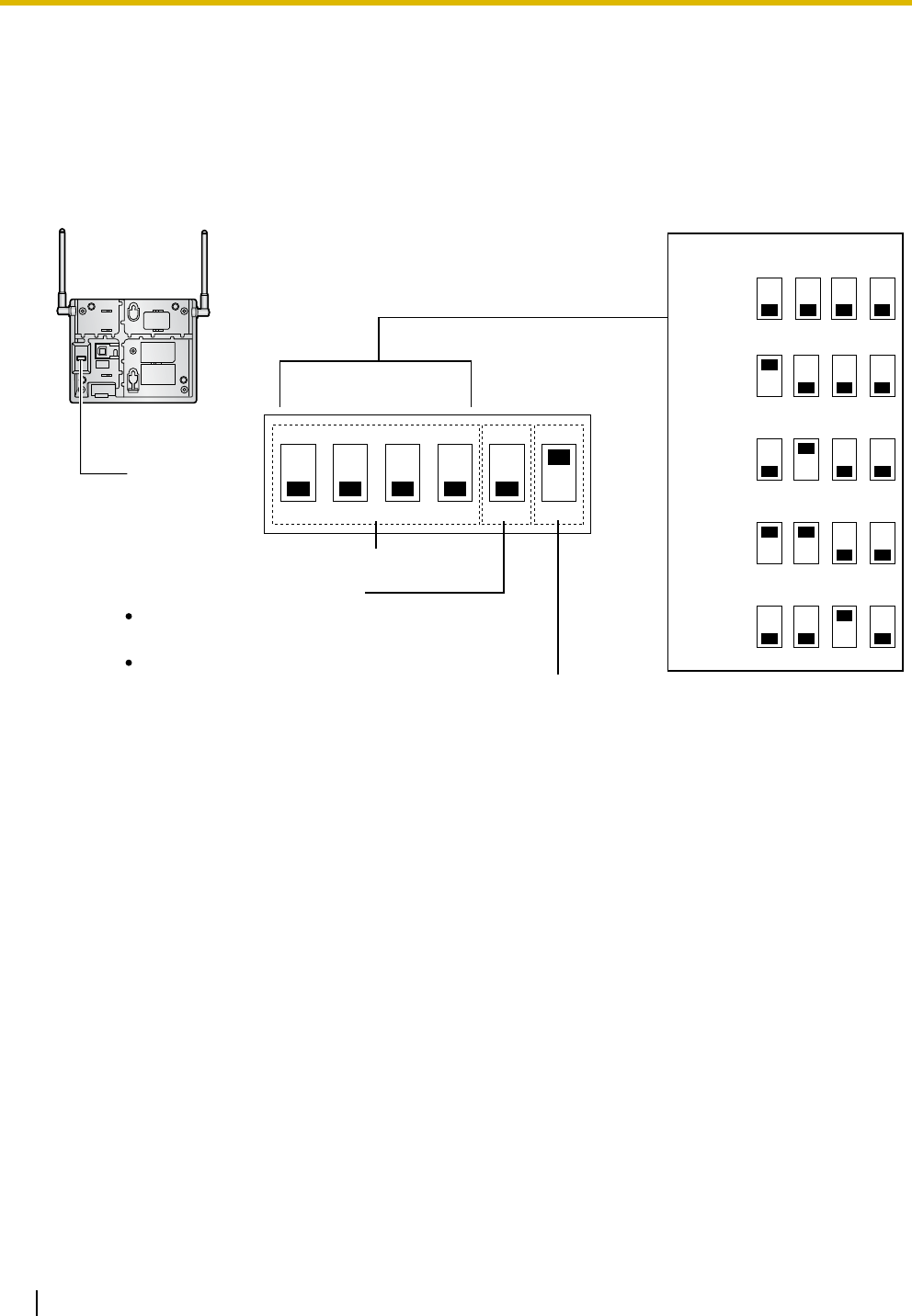
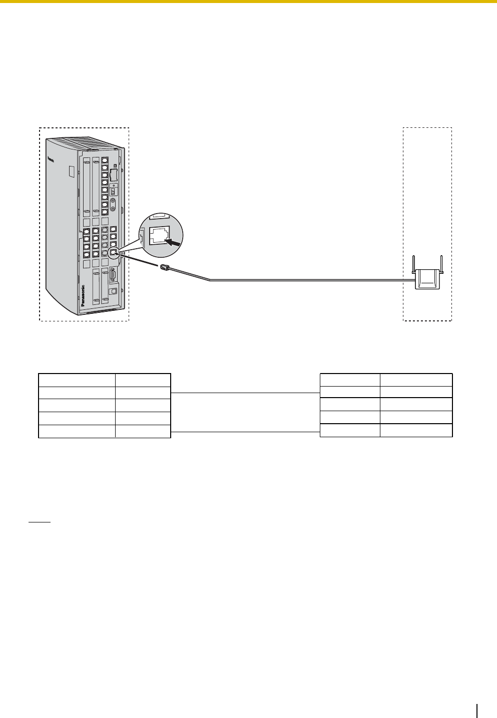
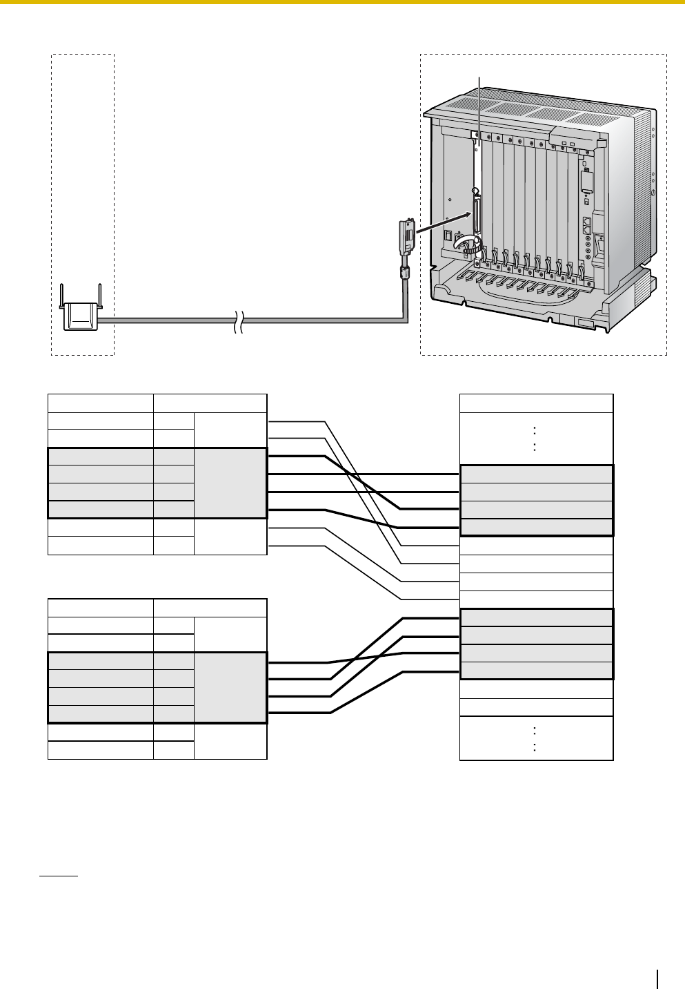
KX-T0158 connecting to KX-TDE100/KX-TDE200
Accessories and User-supplied Items for the CS
Accessories (included): Screws × 2, Washers × 2
User-supplied (not included): RJ45 connector
Notes
• The no. 3, 4, 5 and 6 pins (Master) of the CS must be connected to 2 pairs of pins on the DHLC/
DLC card.
D1B
D2B
D1C
D2C
D1D
D2D
D1E
D2E
D1F
D2F
D1G
D2G
D1H
D2H
1
2
3
4
5
6
7
8
D1C
D2C
D1B
D2A
D2B
D1D
D2D
D1A
1
2
3
4
5
6
7
8
D1C
D2C
D1B
D2A
D2B
D1D
D2D
D1A
CS 1 (RJ45)
CS 2 (RJ45)
Signal Name
DHLC/DLC card (Amphenol)
DHLC8 Card
Pin No.
Signal Name
Master
Pin No.
Signal Name
Master
Maximum Distance
222 m (728 ft)
347 m (1138 ft)
500 m (1640 ft)
347 m (1138 ft)
Cable
26 AWG:
24 AWG:
22 AWG:
CAT 5:
7 Connecting a Cell Station to the PBX
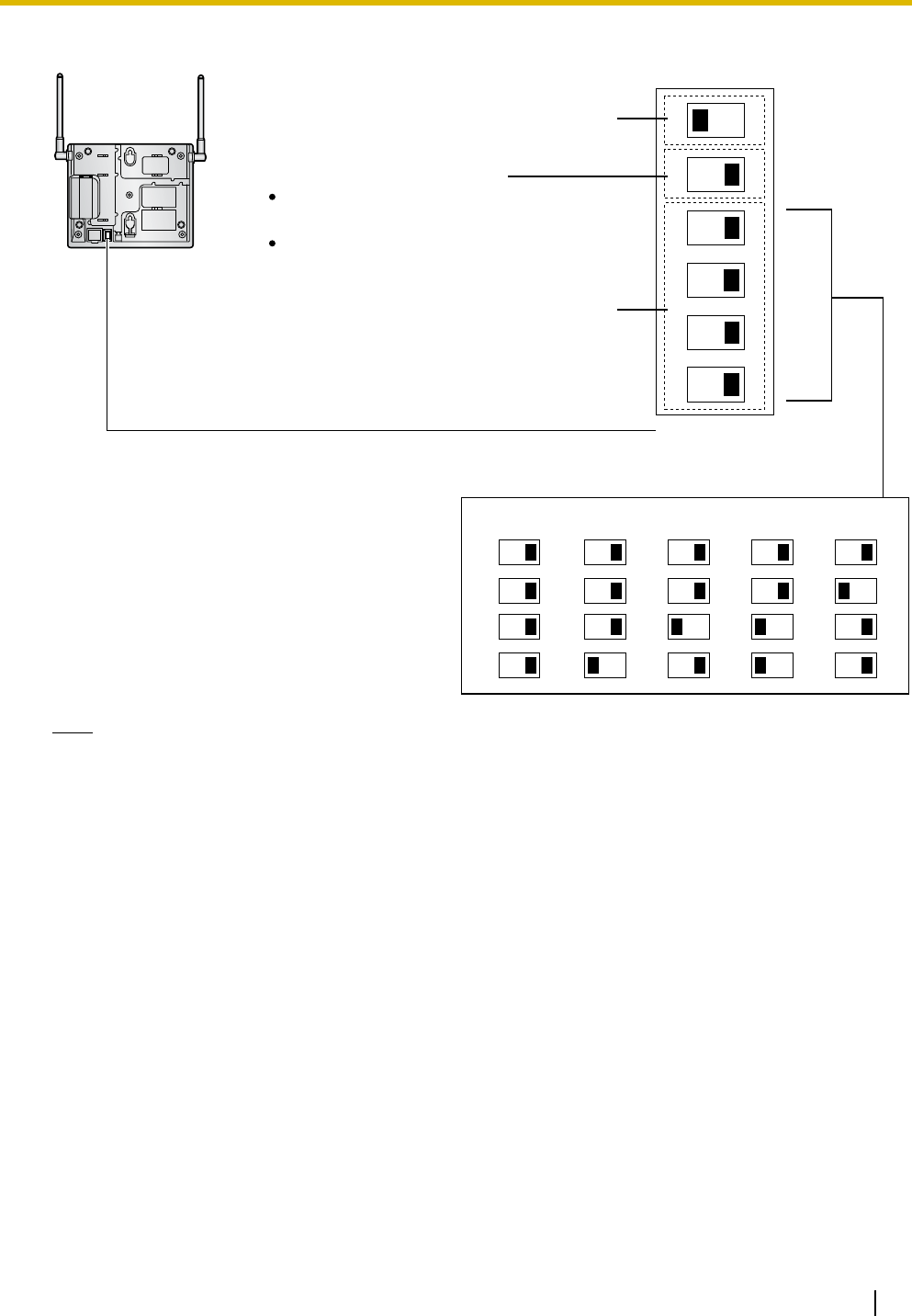
26 Quick Installation Guide
• When connecting multiple KX-T0158 CSs to a DHLC/DLC card, make sure that the no. 3, 4, 5 and
6 pins (Master) of adjacent CSs are at least 2 pairs of pins away on the card.
• For details about the DHLC/DLC card, refer to the Installation Manual for your PBX.
• The Local Processor (LPR) software of the DHLC/DLC card used must be version 5.000 or later.
If necessary, upgrade the LPR software of the DHLC/DLC card. To confirm the LPR software
version of the card, refer to "Configuration— Slot— Summary" in the PC Programming Manual for
your PBX.
• CS connections must be made within the same DHLC/DLC card.
• When a wrong connection is made, satisfactory performance of the CS cannot be guaranteed.
Check the connection of CS and the PBX using the Maintenance Console. For information about
how to view CS information using the Maintenance Console, refer to "Utility—CS Information" in
the PC Programming Manual for your PBX.
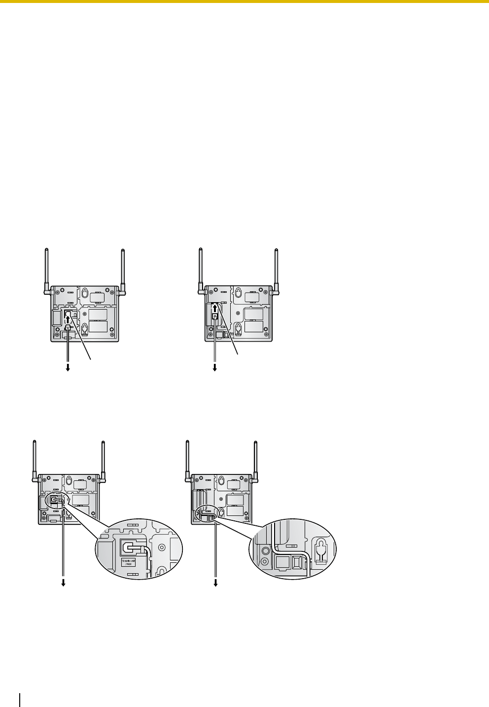
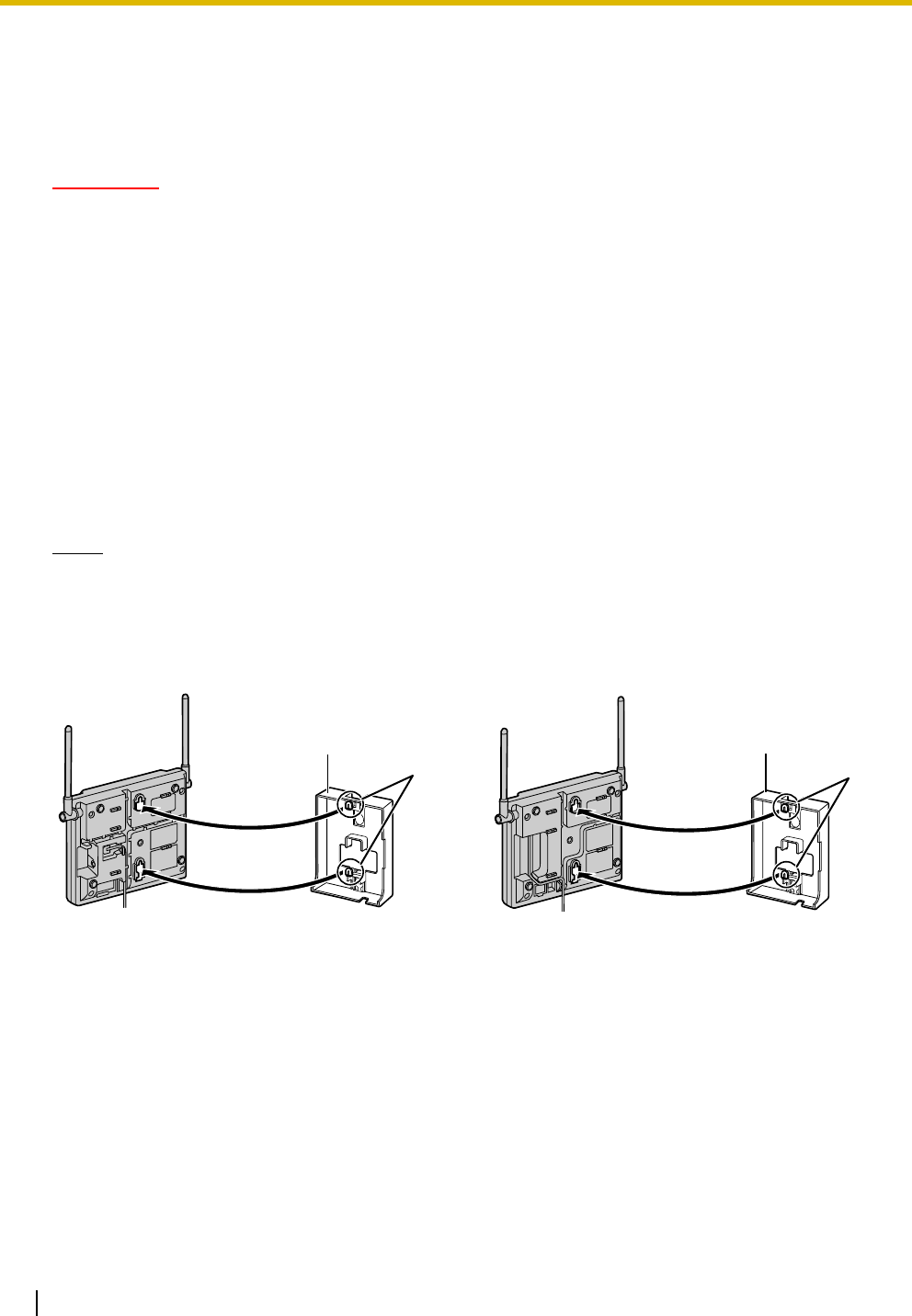
Connecting the CS
1. Connect the cable from the PBX to the CS.
2. Pass the cable through the groove of the CS (in any direction depending on your preference).
KX-T0155 KX-T0158
KX-T0155 KX-T0158
RJ11 Modular
To PBX
RJ45 Modular
To PBX
To PBX
To PBX
7 Connecting a Cell Station to the PBX
Quick Installation Guide 27
Registering the PS
The PS must be registered to the PBX before it can be used. Programming of both the PS and PBX is
required. A Proprietary Telephone (PT) with multiline display (e.g., KX-T7636 6-line display) is required to
perform the PBX system programming.
Note
For details about system programming using a PT, refer to "PT Programming" in the Feature Manual,
and "PT Programming" in the PT Programming Manual for your PBX.
Entering the System Programming Mode
PT (Administrator Level)
Note
means default value throughout this section.
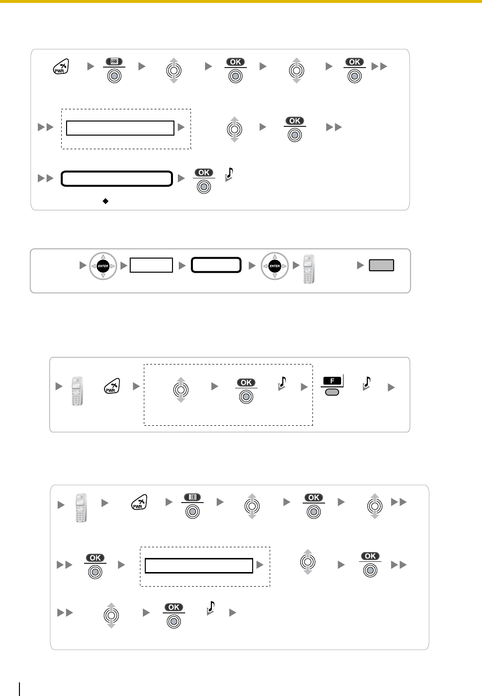
Setting the Personal Identification Number (PIN) for PS Registration
To prevent registering the PS to a wrong PBX, a PIN for PS registration can be set to the PBX. Before
registering the PS to the PBX, enter the PIN set to the PBX into the PS. By doing so, the PS will only be
registered to the PBX with the matching PIN.
Notes
• By default, the PIN for PS registration is "1234" for both the PBX and PS. Therefore, the PS can
be registered to the PBX without setting the PIN.
• The PIN for PS registration will only be used when registering the PS to the PBX. Therefore, during
normal operation after registration, even if there is more than 1 PBX with the same PIN near the
PS, the PS will not be inadvertently linked to a different PBX.
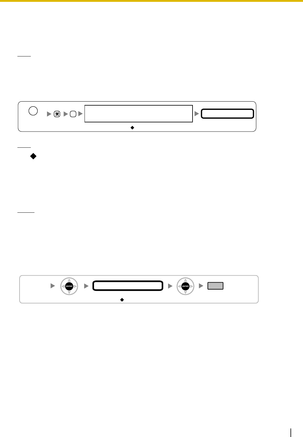
Setting the PIN for PBX
#
1234
System Password for Administrator—
for PT Programming Programming No.
3 digits
PROGRAM/
PAUSE
[692]
4 digits
PIN for PS Registration
END
(HOLD)
ENTER ENTER
1234
7 Connecting a Cell Station to the PBX
28 Quick Installation Guide
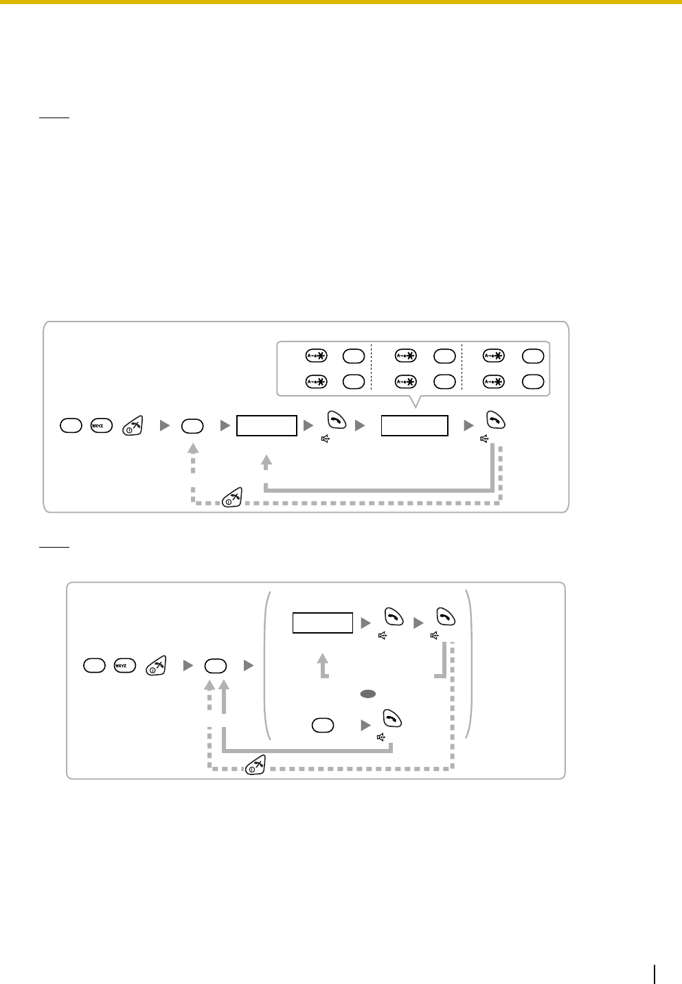
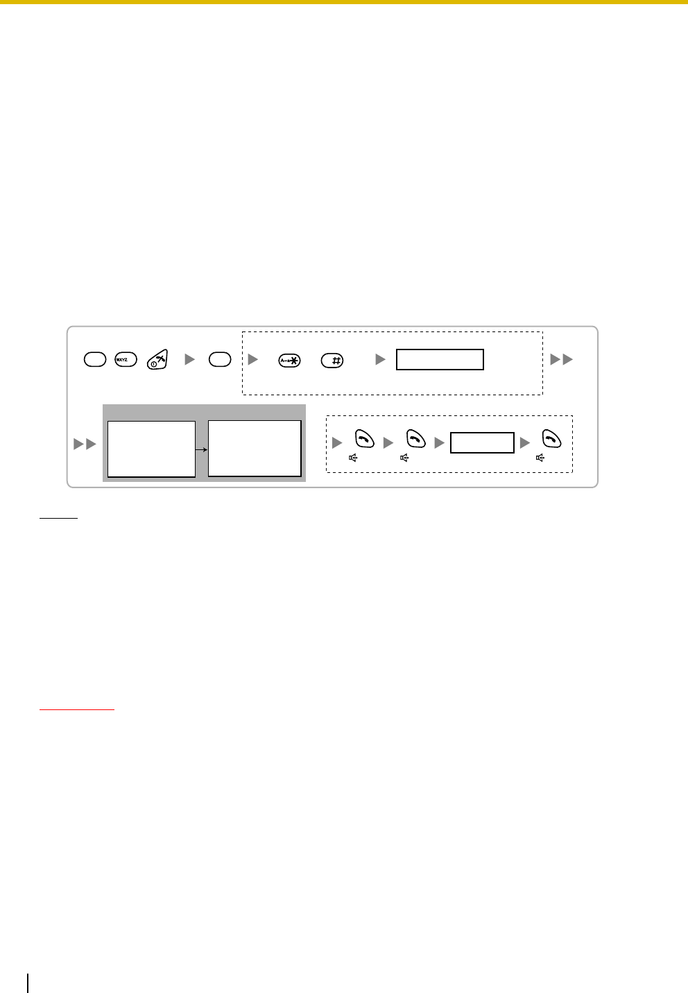
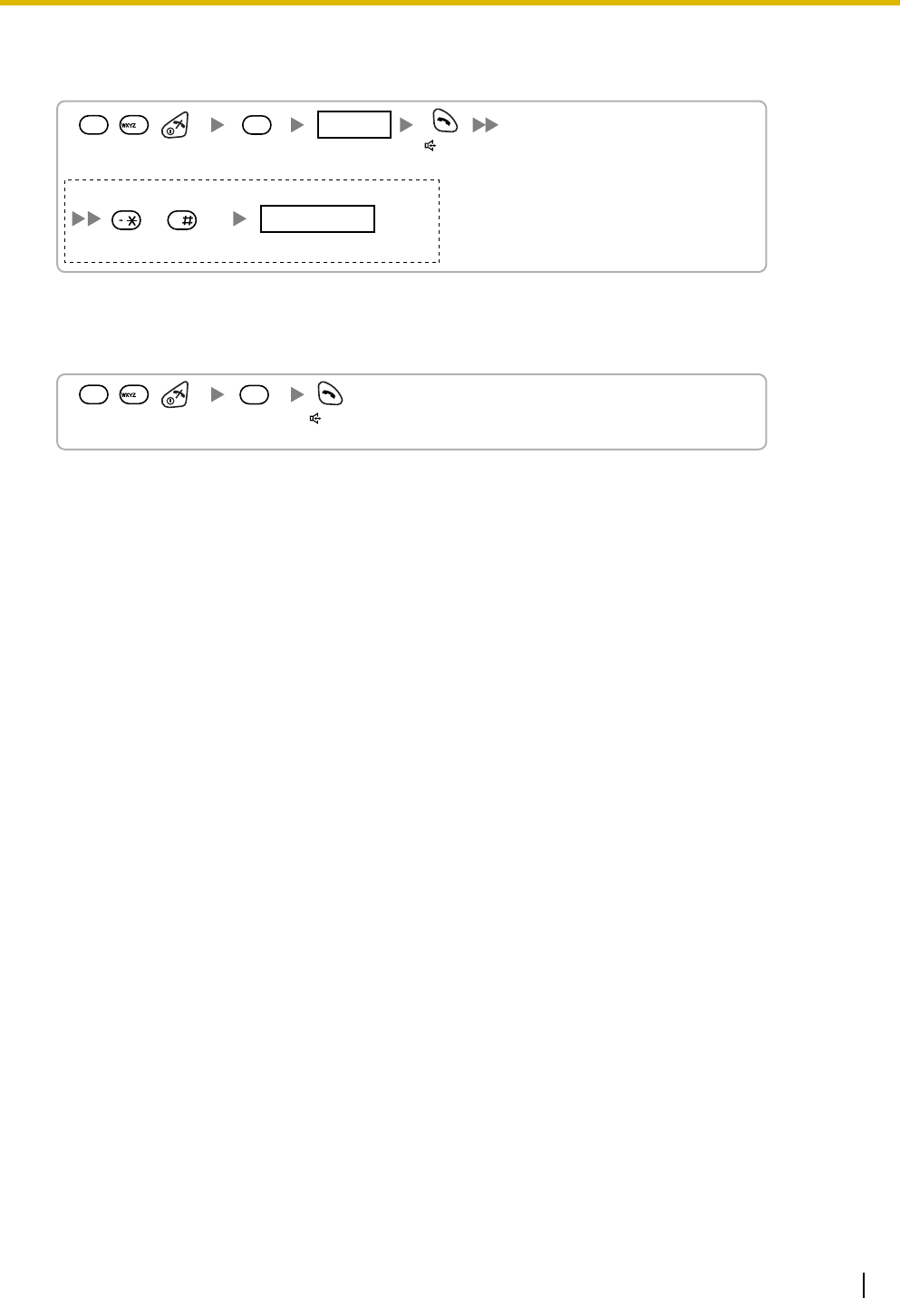
Setting the PIN for PS
Using the KX-TD7685/KX-TD7695
PS Registration
When the PS has not been registered yet
When registering the PS for the first time, it is possible to select the desired language for the display.
(You do not need to enter the PS system programming mode when registering for the first time.)
Using the KX-TD7685/KX-TD7695
When the PS has already been registered to another PBX
One PS can be registered to a maximum of 4 different PBXs.
Using the KX-TD7685/KX-TD7695
Select
"Change PIN".
1 to 8 digits
1234
C.Tone
PIN for PS Registration
Press POWER
for 2 seconds. Select
"Setting Handset". Select
"System Option".
If required
4 digits
System Lock Password
[690]
001 to 128
PS No.
1 to 4 digits END
(HOLD)
ENTER ENTER
To the PS
operation
below
Extn. No.
Press
POWER for
2 seconds.
Select the desired
language
.
Press "F"
for 2
seconds.
C.Tone C.Tone
If required
Select the desired
base (Base 1–4).
Select
"
Register H/S
".
C.Tone
Press POWER
for 2 seconds. Select
"Setting Handset". Select
"System Option".
If required
4 digits
System Lock Password
7 Connecting a Cell Station to the PBX
Quick Installation Guide 29
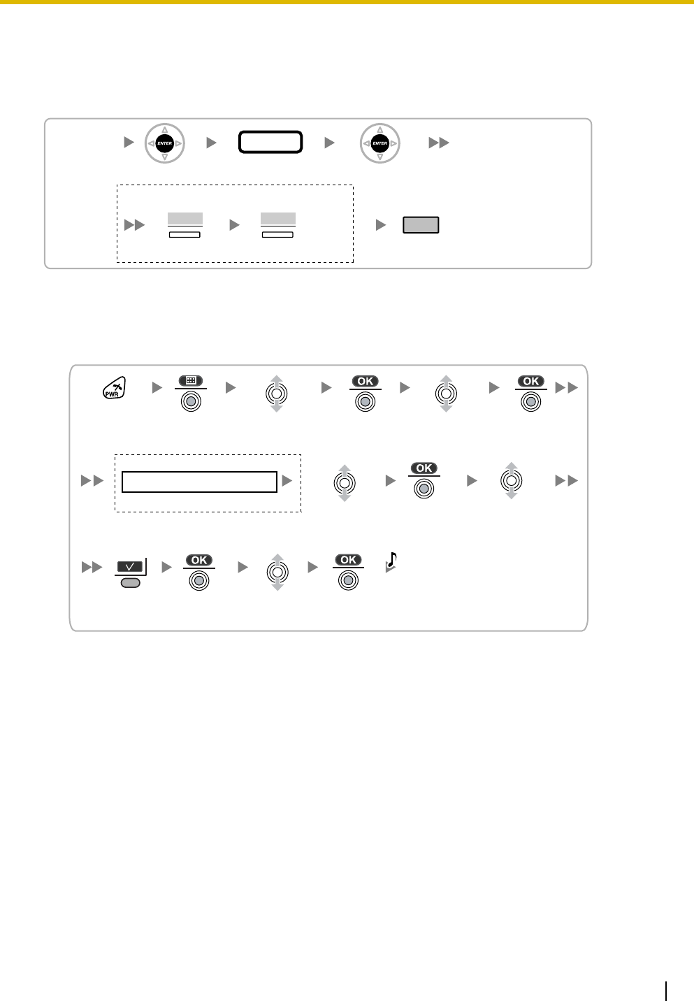
PS Termination
Confirm the following before canceling the PS registration:
• The PS is turned on.
• The PS is within range.
If "Rejected" or "Time out" is displayed
The registration information is still stored in the PS. You need to delete the registration information from
the PS.
Using the KX-TD7685/KX-TD7695
Testing the Operation
Walk around the service area while having a conversation using a registered PS. If noise is frequent or
conversations disconnect, relocate the CSs or install an additional CS.
[691]
001 to 128
PS No.
ENTER ENTER
END
(HOLD)
If "Rejected" or "Time out" is displayed
CLEAR YES
Press "YES".Press "CLEAR".
Select the desired
base (Base 1–4).
Select "Yes".
C.Tone
Select
"Cancel Base".
Press POWER
for 2 seconds. Select
"Setting Handset". Select
"System Option".
If required
4 digits
System Lock Password
8 Wall Mounting
30 Quick Installation Guide
8 Wall Mounting
Mounting the KX-T0155/KX-T0158
WARNING
• MAKE SURE THAT THE WALL THAT THE UNIT WILL BE ATTACHED TO IS STRONG
ENOUGH TO SUPPORT THE UNIT (APPROX. 310 g [11 oz]). IF NOT, IT IS
NECESSARY FOR THE WALL TO BE REINFORCED.
• ONLY USE THE WALL-MOUNTING EQUIPMENT (SCREWS, WASHERS, WALL
MOUNTING PLATE) INCLUDED WITH THE UNIT.
• WHEN DRIVING THE SCREWS INTO THE WALL, BE CAREFUL TO AVOID
TOUCHING ANY METAL LATHS, WIRE LATHS OR METAL PLATES IN THE WALL.
• WHEN THIS PRODUCT IS NO LONGER IN USE, MAKE SURE TO DETACH IT FROM
THE WALL.
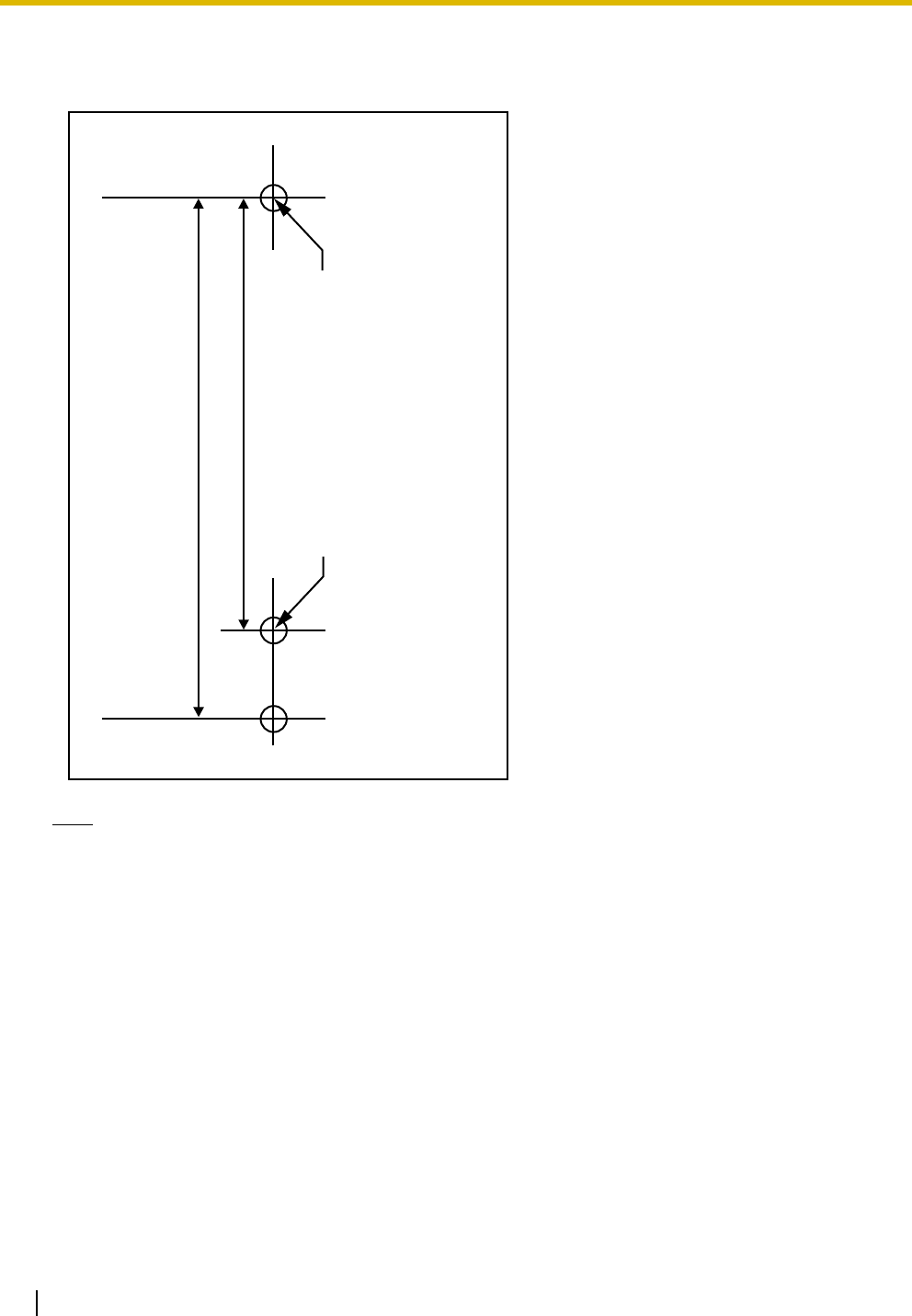
1. Place the reference for wall mounting on the wall to mark the 2 screw positions.
2. Install the 2 screws and washers (included) into the wall.
Notes
• Make sure that the screw heads are at the same distance from the wall.
• Install the screws perpendicular to the wall.
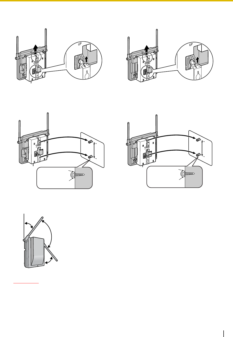
3. Insert the upper and lower tabs of the wall mounting plate into the designated openings in the base unit.
KX-T0155 KX-T0158
Tabs
Wall Mounting Plate
(PSKL1032Y4)
Tabs
Wall Mounting Plate
(PSKL1032Y4)
8 Wall Mounting
Quick Installation Guide 31
4. Slide the wall mounting plate in the direction of the arrow until it clicks.
5. Hook the CS on the screw heads.
6. Place the antennas so that they are pointing in directions that are 90 degrees apart (for antenna
diversity), as follows:
CAUTION
Make sure the cables are securely fastened to the wall.
KX-T0155 KX-T0158
KX-T0155 KX-T0158
Washer
Drive the screw
to this point.
Drive the screw
to this point.
Washer
45º
45º
90º
8 Wall Mounting
32 Quick Installation Guide
Reference for Wall Mounting
Please copy this page and use as a reference for wall mounting.
Note
Make sure to set the print size to correspond with the size of this page. If the dimension of the paper
output still deviates slightly from the measurement indicated here, use the measurement indicated
here.
Install a screw here.
Install a screw here.
83 mm
(3-1/4 in)
100 mm
(3-15/16 in)
9 Troubleshooting
Quick Installation Guide 33
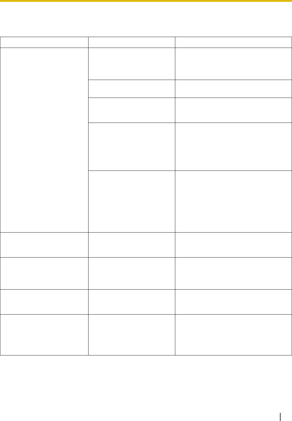
9 Troubleshooting
PROBLEM PROBABLE CAUSE SOLUTION
• The LED of the CS does not
change to Green ON. • CS is not connected
properly. • Make sure that the cable is connected
properly with correct pin assignments.
Also, make sure that the cable does not
make short circuits.
• CS is not set for normal
operation. • Switch all DIP switches off.
• The status of the port that
the CS is connected to is
Out of Service.
• Change the port status from Out of
Service to In Service using the
Maintenance Console.
<KX-T0158 only>
• The Local Processor (LPR)
software of the
corresponding DHLC/DLC
card is not version 5.000 or
later.
• Upgrade the LPR software of the
DHLC/DLC card.
<KX-T0158 only>
• Both KX-T0158 and KX-
T0155 CSs are connected
to the same card, and the
KX-T0158 CSs are
connected to higher-
numbered pins on the card
than the KX-T0155 CSs.
• Connect the KX-T0158 CSs to lower-
numbered pins on the card than the KX-
T0155 CSs.
• Connect the KX-T0158 and KX-T0155
CSs to different cards.
• The LED of the CS stays
Red ON during normal
operation.
• CS malfunction • Replace the CS.
• "CLEAR SCAN DATA" is
displayed on the PS's
screen after turning on the
PS.
• The PS cannot be used for
normal operation when
scan data is stored on the
PS.
• Clear the scan data by following the
procedure described in "Clearing the
Stored Scan Data" in this guide.
• Cannot register the PS. • Wrong Personal
Identification Number (PIN)
is registered to the PS.
• Enter the PIN set to the PBX into the
PS.
• PS becomes out of range.
• Cannot make calls using the
PS.
• Location of CS is not good.
• Access system of the PS is
not properly set.
• Locate the CS properly (refer to "5 Site
Survey").
• Change the access system setting of
the PS to the appropriate system or
automatic.

9 Troubleshooting
34 Quick Installation Guide
• Noise is frequent while using
the PS.
• Conversations disconnect
while using the PS.
• "NO SERVICE" is displayed
on the PS's screen.
• Call handover is not
working.
• PS is out of CS coverage
area.
• Locate the CS properly (refer to "5 Site
Survey").
• The CS is not busy (i.e., the
status of the LED is not
Moderate Green Flashing),
but calls cannot be made or
received.
• There is noise during a
phone call.
• CSs are located too close
together in the same area. • Reduce the number of CSs in the area,
or increase the distance between CSs
(refer to "5 Site Survey").
• PS stays out of service
when the CS status is
changed from Out of
Service to In Service.
• It may take about 20 s for
the CS to start up after the
status has been changed to
In Service.
• Wait until the CS starts up.
PROBLEM PROBABLE CAUSE SOLUTION

9 Troubleshooting
Quick Installation Guide 35

Copyright:
This material is copyrighted by Panasonic Communications Co., Ltd., and may be reproduced for internal use
only. All other reproduction, in whole or in part, is prohibited without the written consent of Panasonic
Communications Co., Ltd.
2008 Panasonic Communications Co., Ltd. All Rights Reserved.
KK0108EK0 (v0.013)
PSQX4669ZA
Panasonic Consumer Electronics Company,
Division of Panasonic Corporation of North America
One Panasonic Way, Secaucus, New Jersey 07094
Panasonic Puerto Rico, Inc.
San Gabriel Industrial Park, Ave. 65 de Infantería, Km. 9.5,
Carolina, Puerto Rico 00985
http://www.panasonic.com/csd