Panasonic of North America 9TAK-SAP14 DECT 6.0 Wireless Access Point User Manual
Panasonic Corporation of North America DECT 6.0 Wireless Access Point
User manual
1.9GHz Wireless Access Point
K-SAP14
CONTENTS
Important safety instructions
Major operating controls and their functions
Operating procedures
Functions and settings
Connections
Precautions for installation
Installation
Specifications
Accessories

FCC CAUTION
Changes or modifications not expressly approved by the party responsible for compliance could void the
user’s authority to operate the equipment.
This device complies with part 15 of the FCC Rules. Operation is subject to the following two conditions: (1)
This device may not cause harmful interference, and (2) this device must accept any interference received,
including interference that may cause undesired operation.
Note: This equipment has been tested and found to comply with the limits for a Class A digital device,
pursuant to part 15 of the FCC Rules. These limits are designed to provide reasonable protection against
harmful interference when the equipment is operated in a commercial environment. This equipment
generates, uses, and can radiate radio frequency energy and, if not installed and used in accordance with
the instruction manual, may cause harmful interference to radio communications. Operation of this
equipment in a residential area is likely to cause harmful interference in which case the user will be required
to correct the interference at his own expense.
Compliance with FCC requirement 15.407(c)
Data transmission is always initiated by software, which is the passed down through the MAC, through the
digital and analog baseband, and finally to the RF chip. Several special packets are initiated by the MAC.
These are the only ways the digital baseband portion will turn on the RF transmitter, which it then turns off
at the end of the packet. Therefore, the transmitter will be on only while one of the aforementioned packets
is being transmitted. In other words, this device automatically discontinue transmission in case of either
absence of information to transmit or operational failure.
Radio Frequency (RF) Exposure Warning
This equipment complies with FCC radiation exposure limits set forth for an uncontrolled environment and
meets the FCC radio frequency (RF) Exposure Guidelines. This equipment should be installed and
operated keeping the radiator at least 20cm or more away from person’s body.
MEDICAL:
Consult the manufacturer of any personal medical devices, such as pacemakers, to determine if they are
adequately shielded from external RF (radio frequency) energy. The unit operates in the frequency range of
1.92 GHz to 1.93 GHz.
Do not use the unit in health care facilities if any regulations posted in the area instruct you not to do so.
Hospitals or health care facilities may be using equipment that could be sensitive to external RF (radio
frequency) energy.
Notice
FCC ID can be found on the bottom of the units.
The model number and serial number of this product may be found on the surface of the unit.
You should note the model number and serial number of this unit in the space provided and retain this
book as a permanent record of your purchase to aid identification in the event of theft.
Model No.
Serial No.
WARNING:
- The mains plug or an appliance coupler shall remain readily operable.
- To prevent injury, this apparatus must be securely attached to the floor/wall in accordance with the
installation instructions.
- The connections should comply with local electrical code.
- The installation shall be carried out in accordance with all applicable installation rules.
- To reduce the risk of fire or electric shock, do not expose this apparatus to rain or moisture.
- The apparatus should not be exposed to dripping or splashing and that no objects filled with liquids, such
as vases, should be placed on the apparatus.
- All work related to the installation of this product should be made by qualified service personnel or system
installers.
- This product has no power switch. When turning off the power, disconnect the power supply from the PoE
device.
CAUTION:
Before attempting to connect or operate this product, please read the label on the bottom.

Important safety instructions
1) Read these instructions.
2) Keep these instructions.
3) Heed all warnings.
4) Follow all instructions.
5) Do not use this apparatus near water.
6) Clean only with dry cloth.
7) Do not block any ventilation openings. Install in accordance with the manufacturer's instructions.
8) Do not install near any heat sources such as radiators, heat registers, stoves, or other apparatus (including
amplifiers) that produce heat.
9) Protect the power cord from being walked on or pinched particularly at plugs, convenience receptacles, and
the point where they exit from the apparatus.
10) Only use attachments/accessories specified by the manufacturer.
11) Use only with the cart, stand, tripod, bracket, or table specified by the
manufacturer, or sold with the apparatus. When a cart is used, use caution
when moving the cart/apparatus combination to avoid injury from tip-over.
12) Unplug this apparatus during lightning storms or when unused for long periods of time.
13) Refer all servicing to qualified service personnel. Servicing is required when the apparatus has been
damaged in any way, such as power-supply cord or plug is damaged, liquid has been spilled or objects
have fallen into the apparatus, the apparatus has been exposed to rain or moisture, does not operate
normally, or has been dropped.
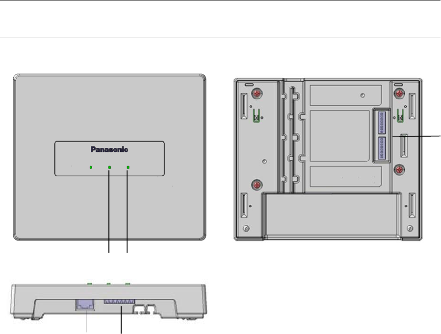
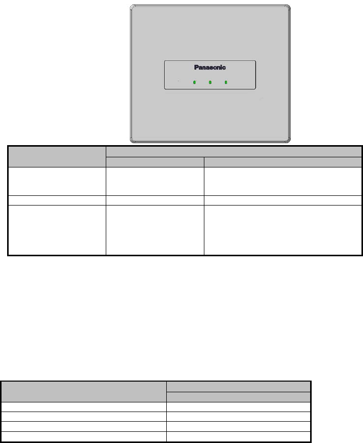
Major operating controls and their functions
2 3
1
6
4 5
[1]POWER indicator
(Green/Red)
This LED lights green when the power is on and this unit is receivable under normal conditions.
This LED lights as follows to indicate other states:
E2 signal output provided: lighting red ( For ONLR Alert)
[2]LINK indicator [OPERATE]
(Green/Red)
This LED lights green when connecting with a receiver.
This LED lights as follows to indicate other states:
E2 signal output provided: lighting red ( For ONLR Alert)
[3]MODE indicator
(Green/Yellow/Red)
This LED lights green when select for sound broadcast state
This LED lights yellow when select for ONLY alert state.
(This LED lights yellow when system error)
[4] Ethernet connector
An RJ-45 type connector of this unit is based on our original system and electrical specifications. Never connect this terminal to a
LAN connector that is compatible with Ethernet and PoE (Power over Ethernet).
[5]Control terminals
8-pin and 7-pin Euro blocks are used.
The following terminals are equipped.
E1 CNT: provides E1 signal * output controlled by K-SAP14.
E2 CNT: provides E2 signal * output controlled by K-SAP14.
* Those are available when K-SAP14 is used. Settings of E1 and E2 are performed with K-SAP14.
E2 ACK: connects acknowledge signals responding to E2 output.
PAGE MUTE: provides make signal inputs externally when the paging function is used.
RS-232C: is used to control this unit via communication from an external device.
LINK button: provides make signal inputs externally when the external link button is used.
Alert notification button; provides make signal inputs externally when the external Alert notification button is used.
[6]DIP Switches
Two DIP switches are used.
DIP switch 1 can select the operation mode of each function equipped in this unit.
The settings of this switch are updated at the time of turning on the power.
From No.1 to No7 of DIP switch 2 are used for selection of group ID.
(It is used at the time of installation of DECT-AP and a receiver.)
Operating procedures
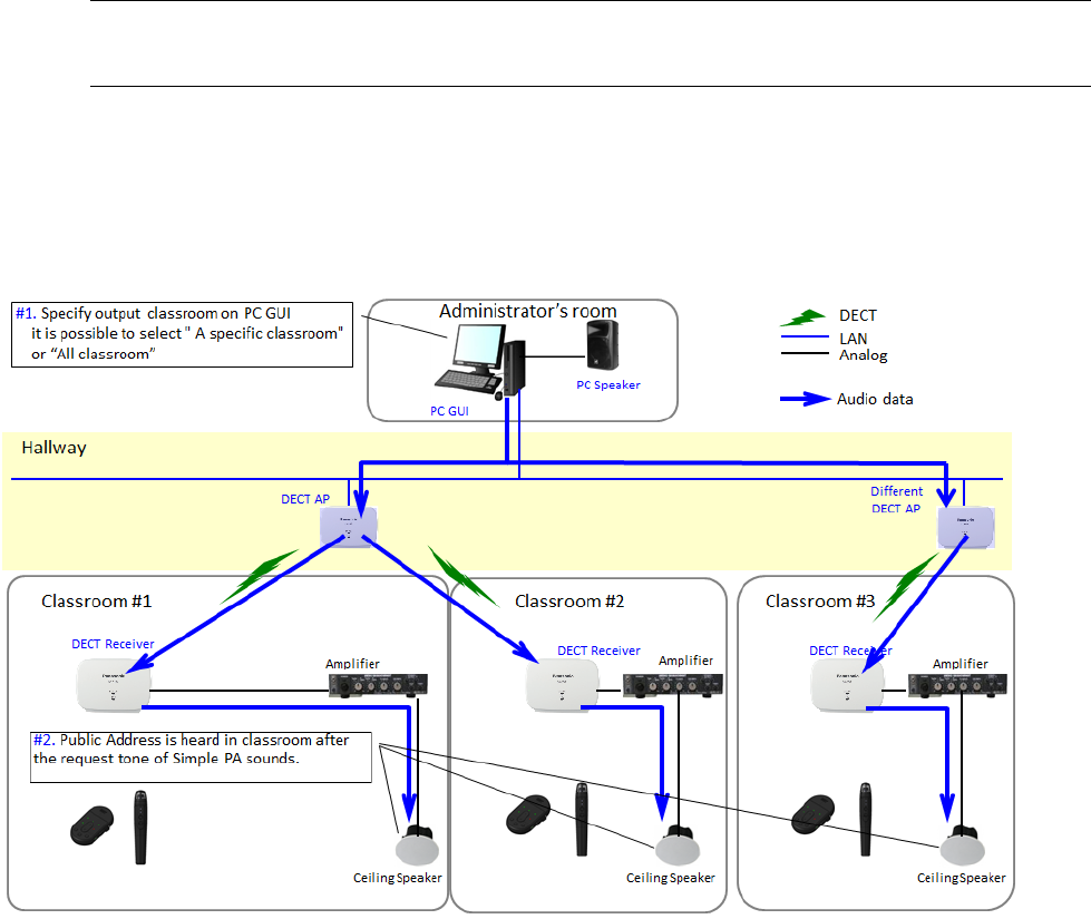
Operation of Simple PA.
1. Specify output classroom on PC GUI it is possible to select "A specific classroom" or "All classroom"
2. Public Address is heard in classroom after the request tone of Simple PA sounds.
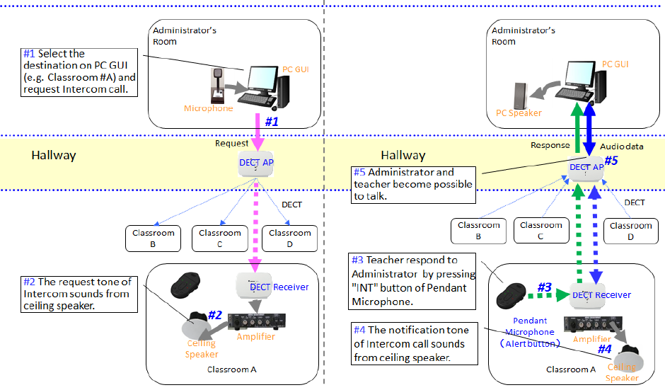
Operation of Intercom
(1) Intercom requested form Administrator’s room to Classroom
1. Select the destination on PC GUI and request Intercom call.
2. The request tone of Intercom sounds from ceiling speaker.
3. Teacher respond to Administrator by pressing "INT/E1" button of Pendant microphone.
4. The notification tone of Intercom call sounds from ceiling speaker after a call was established.
5. Administrator and teacher becomes possible to talk.
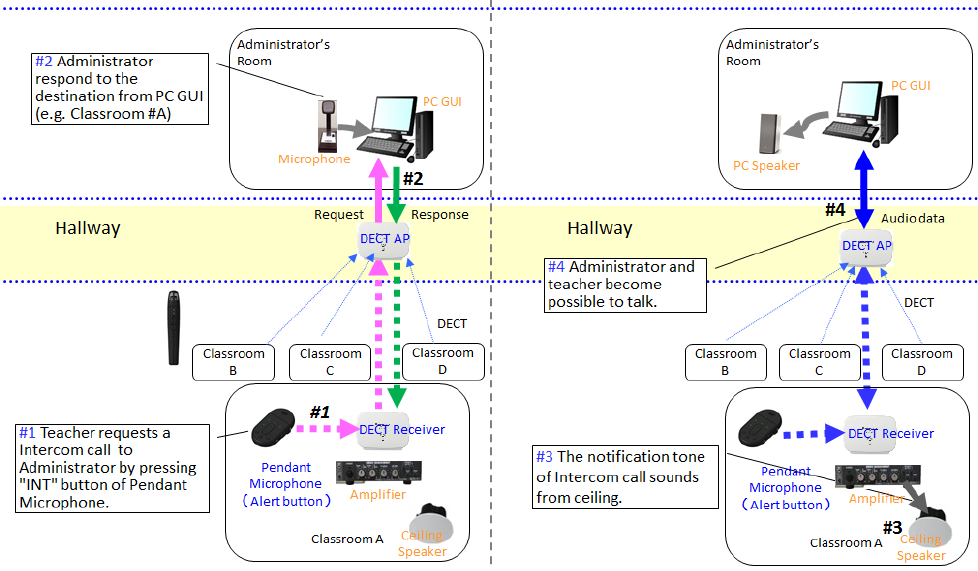
(2) Intercom requested form Classroom to Administrator’s room
1. Teacher requests a Intercom call to Administrator by pressing "INT/E1" button od Pendant microphone.
2. Administrator respond to the destination from PC GUI.
3. The notification tone of Intercom call sounds from ceiling speaker after a call was established.
4. Administrator and teacher becomes possible to talk.
-Audio path number of the intercom is only one in the DECT Microphone System. When intercom have already
being used at the time of the start of it, a tone of BUSY sounds from the ceiling speaker.
Activate E2
Press the both sides [E2] button of the Pendant microphone for 2 seconds or more will activate E2 output and transmit
location information of Pendant microphone.
The voice of Pendant Microphone monitoring
The voice of Pendant Microphone sends to Administrator's room in case of requested from server PC.
Number of audio voice that can send is 1 path per DECT AP.
Please select one, monitoring Pendant microphone
The Microphone is not linked to any receiver.
The Microphone send the Alert message of the Receiver’s of the strong signal level to up to five via the most strong
signal’s Receiver, and the audio voice monitoring function became available via DECT AP.
When a Microphone move:
When Pendant Microphone moves to the out of range, it search nearest receiver or DECT AP (for Alert) and it try to
connect to them.
And Pendant Microphone switches the connection to other receiver, it send Alert notification via the receiver automatically.
Release of an E2 state
The administrator can release the E2 state from administrator PC.
(An individual pendant microphone or the whole system specification can be chosen.)
If Pendant Microphone is power OFF (and charging or out of range), E2 activation operation is done
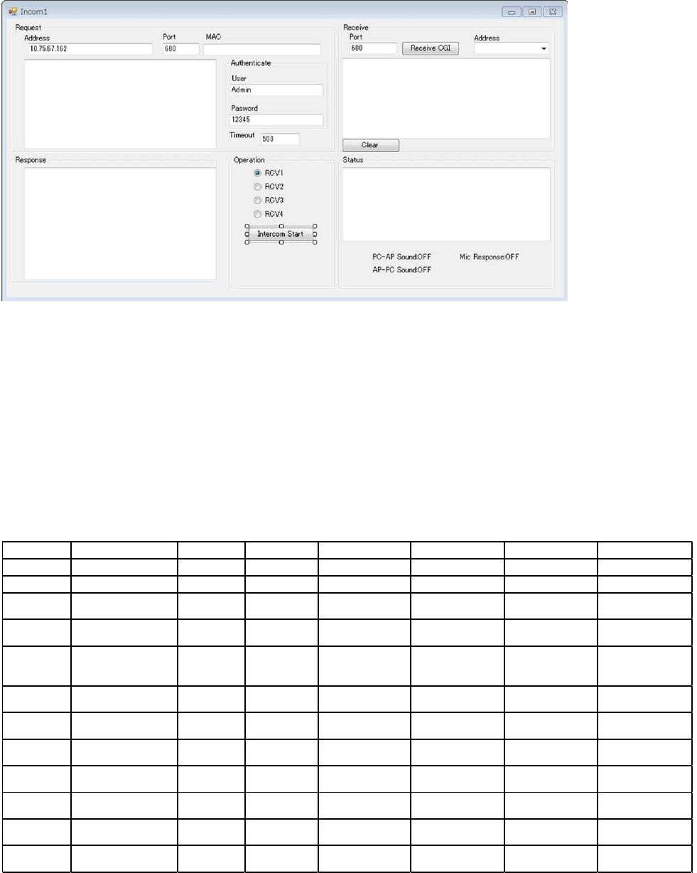
PC operation
PC GUI
reference display ( intercom )
The example of operation
Intercom:
1. Input DECT-AP-IP address/ user name / password.
2. Select the receiver of a classroom which wants to pass intercom.
3. Push “Intercom start” button.
(Operation of Intercom/ Simple PA / Alert monitor can be directed.)
A following CGI command is used for operation.
CGI command list
Command Content Type
Parameter1
Parameter2 Parameter3 Parameter4 Parameter5
regist_start ID registration start setting 1:AP - - - -
regist_end ID registration end setting 1:AP - - - -
rcv_delete
Delete Receiver
registration
setting 1:AP RCV1(ON:Delete) RCV2(ON:Delete) RCV3(ON:Delete) RCV4(ON:Delete)
Mic_delete
Delete Microphone
registration
setting 1:AP,2:RCV MIC-ID - - -
pa_start Simple PA start
Application
control
2:RCV
RCV1
(ON:broadcast)
(OFF:NO)
RCV2
(ON:broadcast)
(OFF:NO)
RCV3
(ON:broadcast)
(OFF:NO)
RCV4
(ON:broadcast)
(OFF:NO)
pa_end Simple PA end
Application
control
2:RCV RCVNo(1-4) - - -
incom_start Intsercom start
Application
control
4:Microphne MIC-ID RCVNo(1-4)
DECTAP
MacAddress
-
incom_end Instercom end
Application
control
2:RCV RCVNo(1-4) - - -
incom_res Intercom response
Application
control
4:Microphne MIC-ID RCVNo(1-4) - -
alert_end Alert end
Application
control
1:AP,2:RCV,
3:AP&RCV
RCVNo(1-4) - - -
monitor_mic monitor start
Application
control
1:AP,2:RCV,
3:AP&RCV
MIC-ID RCVNo(1-4) - -
monitor_mic monitor end
Application
control
1:AP,2:RCV,
3:AP&RCV
0RCVNo(1-4) - -
Functions and settings
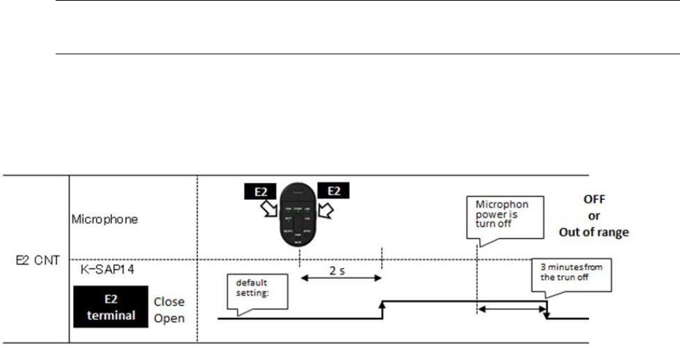
● E2 CNT function
These functions are available when K-SAP14 is used. When E2 is controlled with the microphone, control signals are provided
from the E2 CNT terminal of this unit. Selection between E2 is made at the microphone side.
E2: Default setting is Open.
Press the both sides [E2] button of the microphone for 2 seconds or more or press the alert button to select the close state.
● E2 ACK function
When make signal inputs are provided to E2 ACK of the control terminals during E2 operation, the MIC1 or MIC2 LED indicator of
this unit, MIC1 or MIC2 turns from red to green to indicate that the E2 ACK signal is received.
When the E2 control input has not been provided from the microphone for 3 minutes after turning off the power of the microphone,
the E2 state ends, the MIC1 or MIC2 LED indicator indicates the receiving state, and the operation LED turns from red to green to
indicate the operating state.
LED lighting indication1 [POWER/LINK]
Three LEDs of this unit operate as an operation indicator indicating the state in operation and as a reception indicator indicating
the receiving state of the microphone under normal conditions. In addition to those above, the LEDs operate as an indication LED
indicating the operating state of this unit. Those LEDs indicate operating states as shown in the table.
Furthermore, the priority order of indications is dependent on operating states.
*1 E2 signal outputs and operating the volume button are available only with the microphone, K-STD14.
*2 The indicator lights green again 3 minutes after the E2 signal is turned off with the microphone, K-STD14
LED Indication 2 [MODE LED]
LINK LED is normally off.
When an LINK key is pressed, the LINK LED blinks green.
・LED color will change according to priority. Show in below
Operating state
LED indication
POWER
LINK(receiver)
E2 signal output
provided*1
Red
(Lighting green at E2
ACK input provided)
Red
(Lighting green at E2 ACK input
provided)
Linkup
Green
Green
Power ON
・
During startup
Blink green at 500ms
period
・After startup
Green
No lighting
Status
LED indication
LINK
System error
Red
During ID registration
Blink yellow at 500ms period
For sound broadcast
Green
For ONLY Alert
Yellow
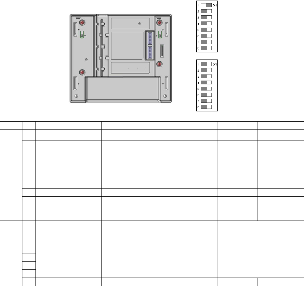
DIP switch setting
Switch No Name Function On Off
Switch1
1
Setting
Selecting “For ONLY Alert” or ”For sound broadcast”.
For ONLY Alert*
For sound
broadcast
2
Version display
To display the software version by LED lighting
pattern as the power is turned on.
Activated Deactivated *
3
Initialize Factory setting
Initialize all internal setting to the
factory-shipments State
Activated Deactivated *
4
Transmission output
control
It allows adjusting the RF power output at
installation by command input via RS232
High(mode2) Low(mode1)*
5
Unused
―
- -
6
Unused
―
- -
7
Unused
―
- -
8
Unused
―
-
-
Switch2
1
DECT AP Group number
setting
Selection of Group ID between Receiver and DECT
AP.
0-127 of Group ID
2
3
4
5
6
7
8
Unused
-
-
-
*default setting
Note:
DIP switch 1 can select the operation mode of each function equipped in this unit.
The settings of this switch are updated at the time of turning on the power.
From No.1 to No7 of DIP switch 2 are used for selection of group ID.
(It is used at the time of installation of DECT-AP and a receiver.)
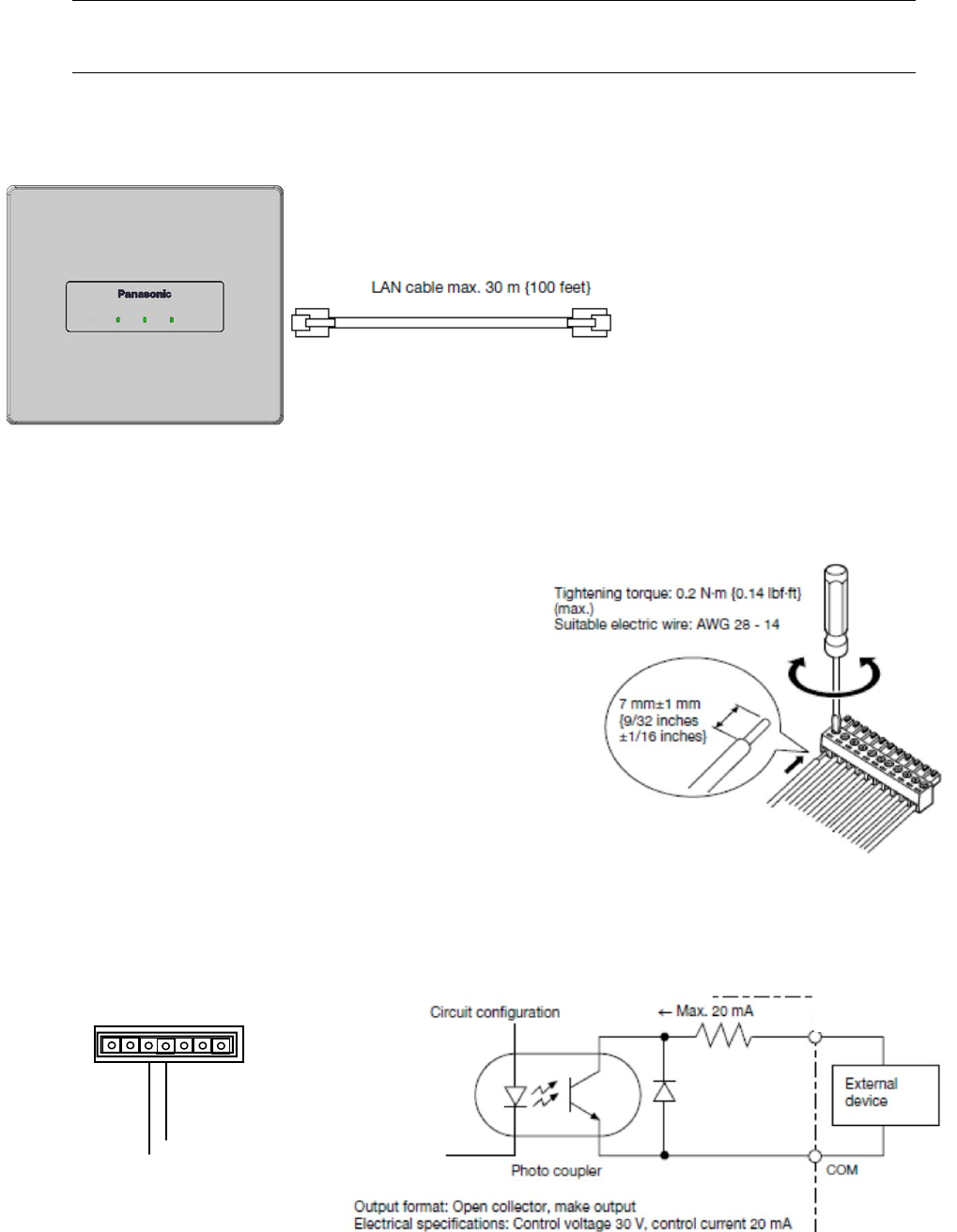
Connections
● LAN(PoE)connection
■ Connection to control terminal
● Cable processing
Before connection, prepare the cable as shown in the drawing at right.
Note:
• Stranded wire is highly recommended.
• Wire insulation must be removed.
• Do not use solder to tin the wire.
• The recommended maximum cable length is 15 m {49feet}.
● Connection of E2 CNT terminals
An external device is connected between E2 CNT and COM. These terminals are isolated from the internal circuit by a photo
coupler.
E2 CNT
E2 COM
E2 CNT
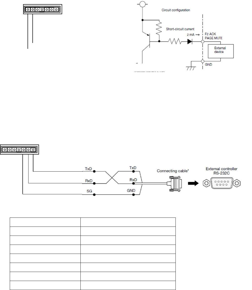
● Connection of ALERT BUTTON terminals
An external device is connected between ALERT BUTTON and GND. These terminals operate by closing their circuits. The GND
terminal is connected to GND in this unit. A set of “dry relay” contacts are recommended to activate these features.
Input format: transistor input
Electrical specifications: Open voltage 5 V DC, short-circuit current 2 mA
■ Connection of RS-232C
The K-SRC14 can send and receive commands and status information via RS-232C to external devices. The external device is
connected with a 3 wire cable. The cable should be cross-connected, in other words, the transmitting signal (TxD) of this unit is
connected to the receiving signal (RxD) of the external device, and the receiving signal (RxD) of this unit is connected to the
transmitting signal (TxD) of the external device. The ground signal of each device should be connected one another.
Cables to be connected should be selected depending on the external devices to be connected. The above illustrates
that the external device has a D-sub 9-pin connector.
Interface
RS-232C
Communication system Asynchronous
Baud rate 9600 bps
Data length 8 bits
Parity None
Stop bit 1 bit
Flow control None
Communication code ASCII character code
ALERT BUTTON
GND
ALERT BUTTON

Precautions for installation
The installation should be carried out following local standards for electric products.
Warning
• Be sure to contact your dealer for installation.
Before installing, turn off the power of the connecting product. In addition, be sure to read "Precautions" carefully and follow the
instructions. Moreover, be sure to read operating instructions of the connecting product as well.
●
Power
Connect the power plug of the AC adaptor by using a circuit breaker in any of the following ways:
Install this product near the power outlet.
Connect this product with the breaker of a distribution board which has a contact point of not less than 3.0 mm {3/32 inches}.
Use a breaker that can block all the poles except for protective earth conductors.
Connect this product via the outlets of devices that can block power such as a power control unit.
●
Static Electricity
Discharge any static electricity charged in your body by touching a metallic area before installing in order to prevent damage
caused by static electricity.
●
Install the receiver within a range that the microphone can reach and in a location that can be seen in moving
range.
●
Avoid installing near a warm air flow path. In addition, if the product is installed in locations with a lot of
moisture, dust or vibration, there is a risk of damage.
●
Do not install and use in following locations:
1) Locations directly affected by rain or water (including spaces under the eaves).
2) Locations such as pool where medical agents are used.
3) Locations such as kitchen or factory workshop where there is a lot of vapor or oil and special environments such as in
flammable atmospheres.
4) Locations where radiation or X-rays and strong electric fields or magnetism arise.
5) At sea or along the coast, and locations such as hot springs where corrosive gases arise.
6) Locations with a lot of vibrations caused by vehicle or ships (this is not a product for vehicles).
7) Locations where water drops made by condensation will splash.
●
If there are any devices releasing strong noises, product may sometimes be impossible to use. In that case,
install the product farther away until it can be used.
●
For tightening bolts and screws, pay attention to following points:
1) Torque control is necessary for tightening the bolts and screws.
2) Torque wrench and torque driver are necessary for controlling the torque.
3) Never use any impact driver or electric drill because torque control is difficult even if they have a clutch. Their use may result in
damage to the mounting part.
●
After mounting, confirm visually that the product is firmly and stably fixed. If the product is properly installed, it
will not wobble or make noise.
●
In installing this receiver, be aware of the following:
1) Be sure that the installation is carried out by a qualified personnel when installing at high locations.
2) Before installation, confirm that there is nobody around.
3) In order to carry out the installation safely and surely, pay close attention to the safety control.
●
Do not apply strong impact on this unit. Failure to observe this may damage this unit.
Please change the user ID/password periodically for security strengthening.
When user authentication goes wrong 8 times or more in 30 seconds from PC of the same IP address (attestation error), it
becomes impossible to access between for a while and this machine.
Preparation Installation
System Setting
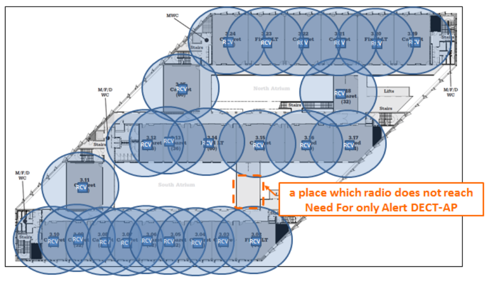
The planning of equipment layout
First: Arrangement of apparatus is planned using a planning tool.
1. The classroom in which a receiver is installed is decided.
2. DECT-AP is arranged in the position where radio reaches a receiver.
(They are a maximum of four receivers which can connect with one DECT-AP. )
3. When there is a place which radio does not reach, the installation for only Alert DECT-AP is considered.
*The measure against misconnection of a DECT-AP and a receiver
Since the pair connection (misconnection) which is not meant by a case may be made, please perform the grouping by Dip
SW attached to a DECT-AP and a receiver.
Refer to DIP switch setting for a setup of Dip SW.
*Memo
The factory setting of a DECT-AP is " FOR ONLY Alert."
To use it as a DECT AP FOR broadcast, a change is required for the DECT AP operation FOR broadcast at a DIP switch.

Installation.
Warning
• Before installing, be sure to turn off the power of the receiver.
There is a risk of electric shock.
■ Installation of the receiver
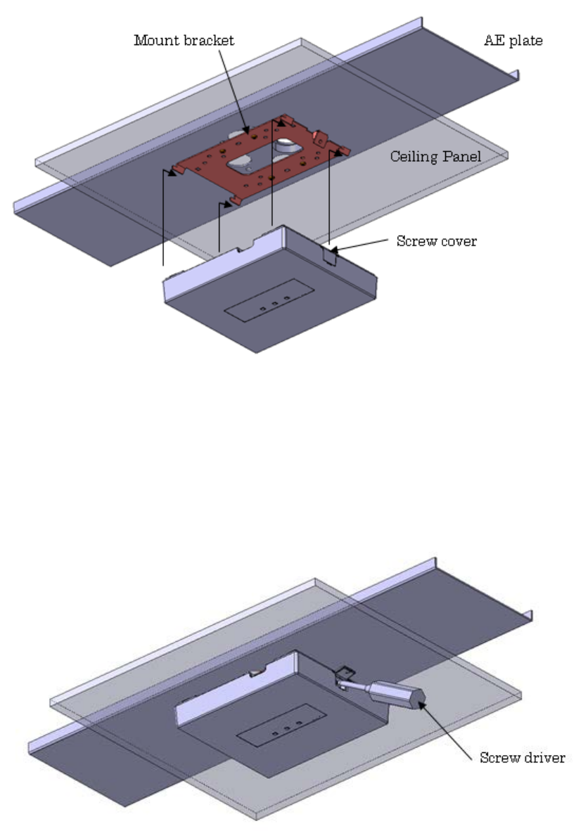
● When using a ceiling panel
When installing the receiver and cables in a removable ceiling, follow the instructions shown below.
1 Make a hole in the ceiling panel
Remove the ceiling panel, drill a hole of approx. φ35 mm {φ1-1/3 inches} through the panel, and run the cables to be connected
through the hole.
2 The ceiling panel is inserted on mount bracket and a plate, and it fixes with a screw and a nut.
Note:
• Fix this unit firmly with specified torque with a tool such as a torque driver.
3 Connect the necessary cables to the receiver.
Connect the cables refer to Connections.
4 Install the receiver.
A receiver is hooked on the hook of the mount bracket.(Four places)
Open the screw cover.
A receiver is fixed to mount bracket with a driver using an attached screw.
Close the screw cover.
Note:
• Fix this unit firmly with specified torque with a tool such as a torque driver.
5 After installation, check that all parts are firmly installed.
Check visually for loose parts and connections.
Step 1
Step 2
● When using a wall
When installing the receiver and cables in a removable wall, follow the instructions shown below.
1 The mount bracket is fixed to a wall with a driver using a screw.
Note:
• Fix this unit firmly with specified torque with a tool such as a torque driver.
2 Connect the necessary cables to the receiver.
Connect the cables refer to Connections.
3 Install the receiver.
A receiver is hooked on the hook of the mount bracket.(Four places)
Open the screw cover.
A receiver is fixed to mount bracket with a driver using an attached screw.
Close the screw cover.
Note:
• Fix this unit firmly with specified torque with a tool such as a torque driver.
4 After installation, check that all parts are firmly installed.
Check visually for loose parts and connections.
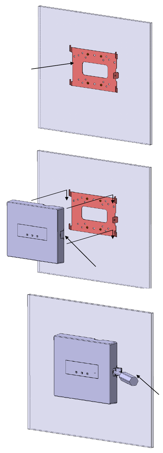
Screw cover
Mount bracket
Screw driver
Step 1
Step 2
Step 3
Setting of the Units
(a)[For sound broadcast] DECT-AP
Pairing registration of the receiver of a DECT-AP
Please supply a power supply to a receiver.
(A receiver will be in a pairing registration state automatically, if a power supply is switched on in the state of
factory shipments.)
After that, DECT-AP is turned on.
Pair registration of a DECT-AP and the receiver is carried out automatically.
Setting of the [For sound broadcast] DECT-AP
Please perform an IP address setup of a DECT-AP by DHCP.
(Since it is necessary to make it not receive the alert from Pendant microphone, the DECT-AP for
broadcast should change system ID from a factory-shipments value.)
Pairing registration of the receiver of a microphone
Pair registration of a microphone and a receiver is performed.
Push the LINK button of a receiver, and push the PWR button of a microphone, after that, pair registration will be performed
automatically.
System Operation Start
When registration of all the receivers, a DECT-AP, and a microphone is completed, a beginning of operation
becomes possible.
Thereby, all the functions become usable.
Extend unit
When you extend a microphone, a receiver, and a DECT-AP, please do the same work as various above-mentioned setup.
*Pairing registration of a receiver and a DECT-AP should work, after stopping the whole system.
Reduced unit
In order to reduce a receiver, the receiver information registered into the access point needs to be deleted.
Although the receiver registration information to four is registered into an a DECT-AP, since it may become impossible for a
new receiver to register if the eliminated receiver information is left behind, please delete.
(b)[For ONLY Alert] DECT-AP
Please install for only Alert DECT-AP in the planned installation position correctly, and switch on a power
supply.

Specifications
General
Power PoE (IEEE 802.3af )
Class Class1
Operating temperature range 0°C - 40 °C {32 °F - 104 °F}
Dimensions 7.28"(W) x 6.3"(H) x 1.26"(D) (185mm(W) x 160mm(H) x 32(D) )
(excluding projections)
Mass
Finish ABS resin white color
RF communication
Radio Standard DECT
Frequency Range 1,920.0~1,930.0MHz
Coverage 20m (NORMAL) / 30m (Hi POWER)
Control terminal
F2 CNT, COM Output format: open collector, make output
Electrical specifications: control voltage; 30 V, control current; 20 mA
ALERT BUTTON Input format: transistor input
Electrical specifications: open voltage; 5 V DC, short-circuit current; 2 mA
RS-232C TxD Compliant with RS-232C, asynchronous, 9600 bps
RxD
SG
LAN Interface
Connectors RJ-45 (Type for LAN)
Recommended Cable LAN(Cat5e or more)
Network Protocol IPv4
100BASE-TX, 10BASE-T(Auto/Full/Half)
Accessories.
Mounting bracket : 1
Tie for cable : 2
Unattached:
Operating Instructions : None. Total operating instructions are prepared by Audio
Enhancement.
Warranty Card : None, the warranty period is described in the contract.