Panasonic of North America 9TAWX-CC412A DECT 6.0 Center Module (with 2 Wireless modules) User Manual
Panasonic Corporation of North America DECT 6.0 Center Module (with 2 Wireless modules) Users Manual
UserManual.wiki
>
Panasonic of North America
>
9TAWX CC412A User Manual
Users Manual
Navigation menu
Upload a User Manual
Namespaces
Wiki Guide
HTML
PDF
Info
Views
User Manual
Discussion / Help
Navigation
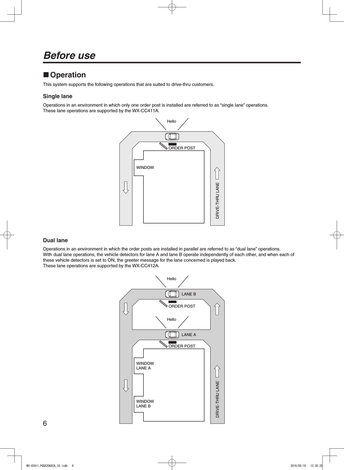
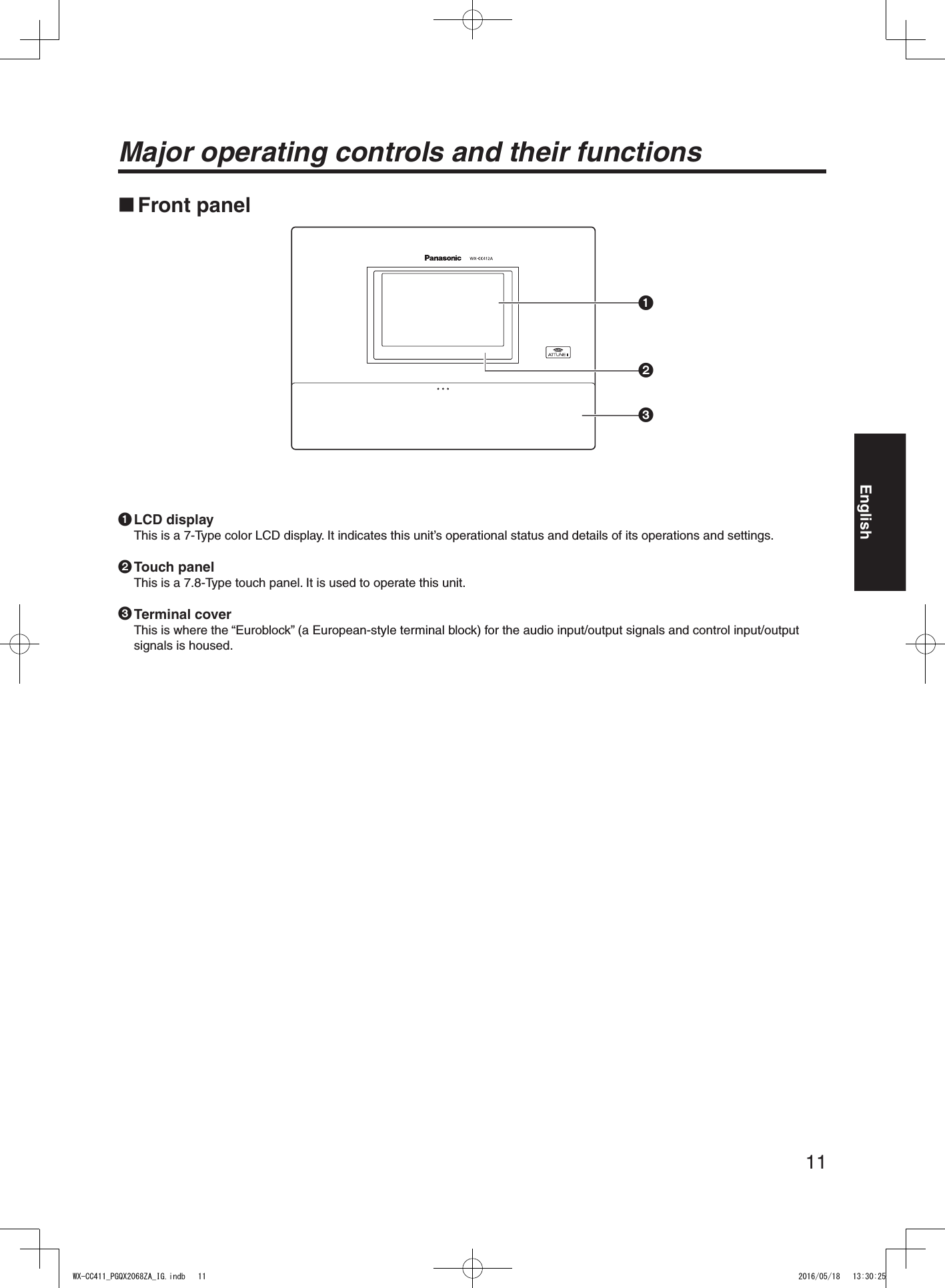
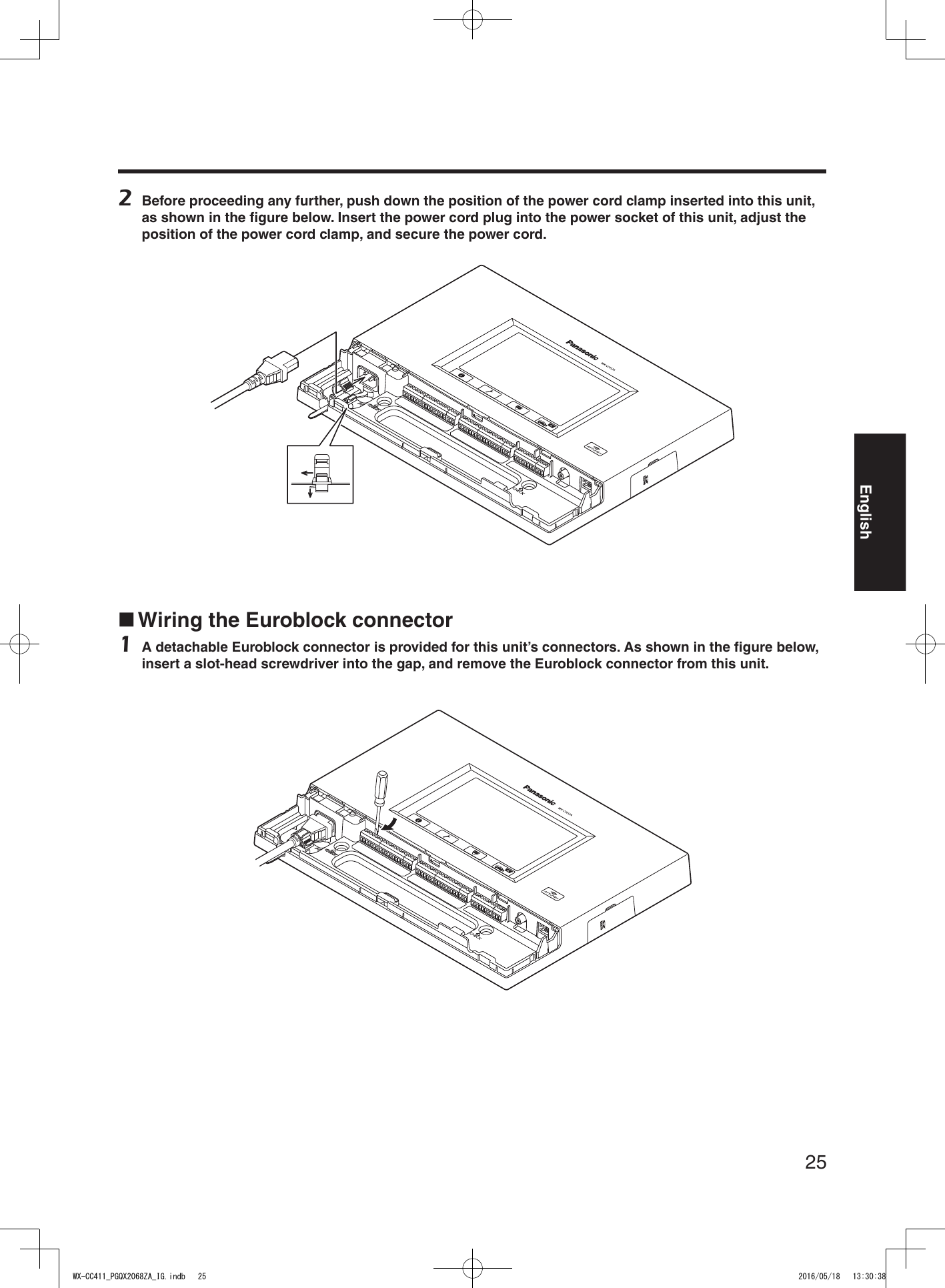
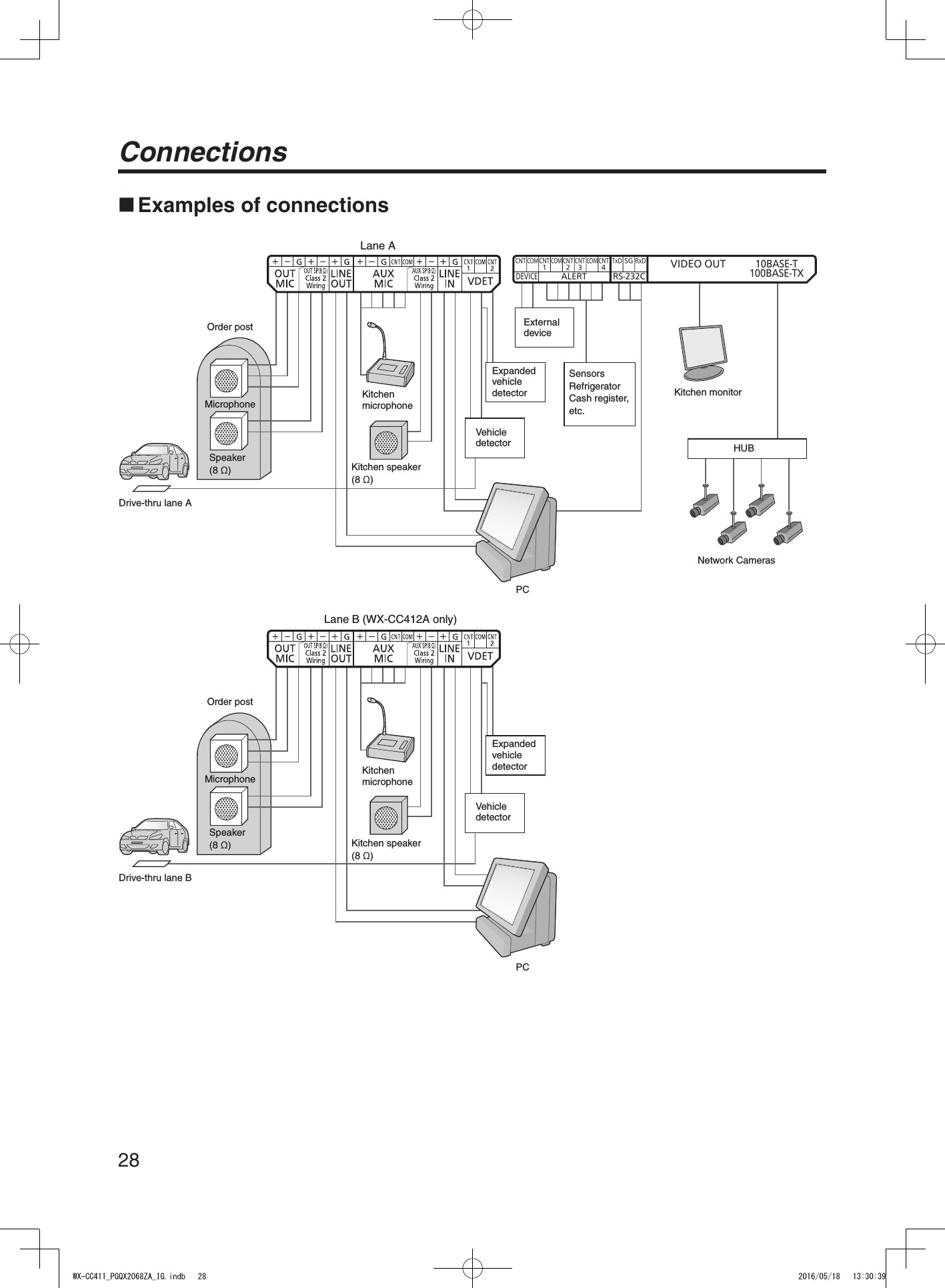
![12Major operating controls and their functions Terminal blockCNT1COMLANE A LANE BCNTDEVICEALERT RS-232CVIDEO OUT10BASE-T100BASE-TXCNT2CNT1CNT3CNT4COMCOM COMTxD RxDSG 4 Power input terminal [AC IN]Connect the accessory power cord to this terminal. After connecting it, secure the cord using the power cord clamp. (Refer to p.24 “Securing the power cord”.)5 Confirmation window [CHECK]This window is used for confirmation purposes when this unit is installed.6 Lane A mic input [OUT MIC]This is connected to the microphone for the order post installed in lane A.7 Lane A speaker output [OUT SP (8 Ω) Class2 Wiring]This is connected to the speaker for the order post installed in lane A.8 Lane A line output [LINE OUT]The same communication that is output from OUT SP of lane A is output.9 Lane A kitchen mic input [AUX MIC]This is connected to the gooseneck microphone installed in the lane A kitchen.It is used to speak with the customer who has arrived at the order post for lane A.: Lane A kitchen speaker output [AUX SP (8 Ω) Class2 Wiring]This is connected to the speaker installed in the lane A kitchen.It is used to speak with the customer who has arrived at the order post for lane A. Lane A line input [LINE IN]External communications can be broadcast simultaneously to all the All-In-One Headsets or Belt Packs and to the lane A kitchen speaker. Lane A vehicle detector input [VDET]This is connected to the vehicle detector installed in lane A. Lane B mic input [OUT MIC]This is connected to the microphone for the order post installed in lane B. Lane B speaker output [OUT SP (8 Ω) Class2 Wiring]This is connected to the speaker for the order post installed in lane B. Lane B line output [LINE OUT]The same communication that is output from OUT SP of lane B is output. Lane B kitchen mic input [AUX MIC]This is connected to the gooseneck microphone installed in the lane B kitchen.It is used to speak with the customer who has arrived at the order post for lane B. Lane B kitchen speaker output [AUX SP (8 Ω) Class2 Wiring]This is connected to the speaker installed in the lane B kitchen.It is used to speak with the customer who has arrived at the order post for lane B. Lane B line input [LINE IN]External communications can be broadcast simultaneously to all the All-In-One Headsets or Belt Packs and to the lane B kitchen speaker. Lane B vehicle detector input [VDET]This is connected to the vehicle detector installed in lane B.WX-CC411_PGQX2068ZA_IG.indb 12 2016/05/18 13:30:25](https://usermanual.wiki/Panasonic-of-North-America/9TAWX-CC412A/User-Guide-3068481-Page-12.png)
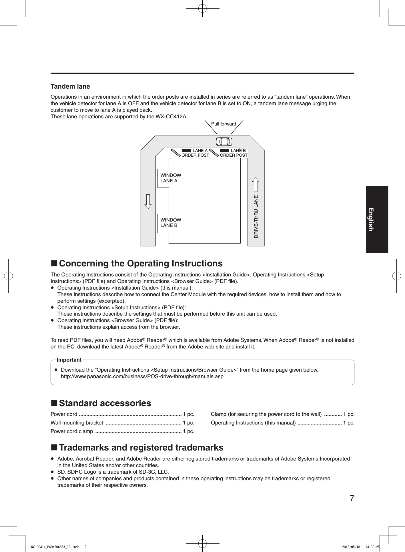
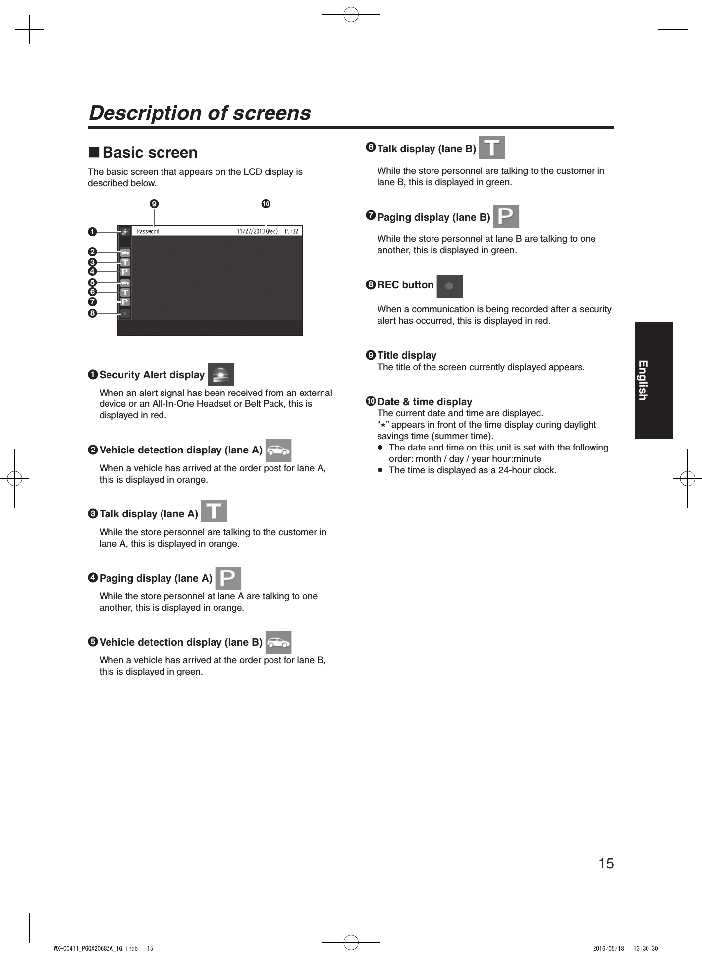
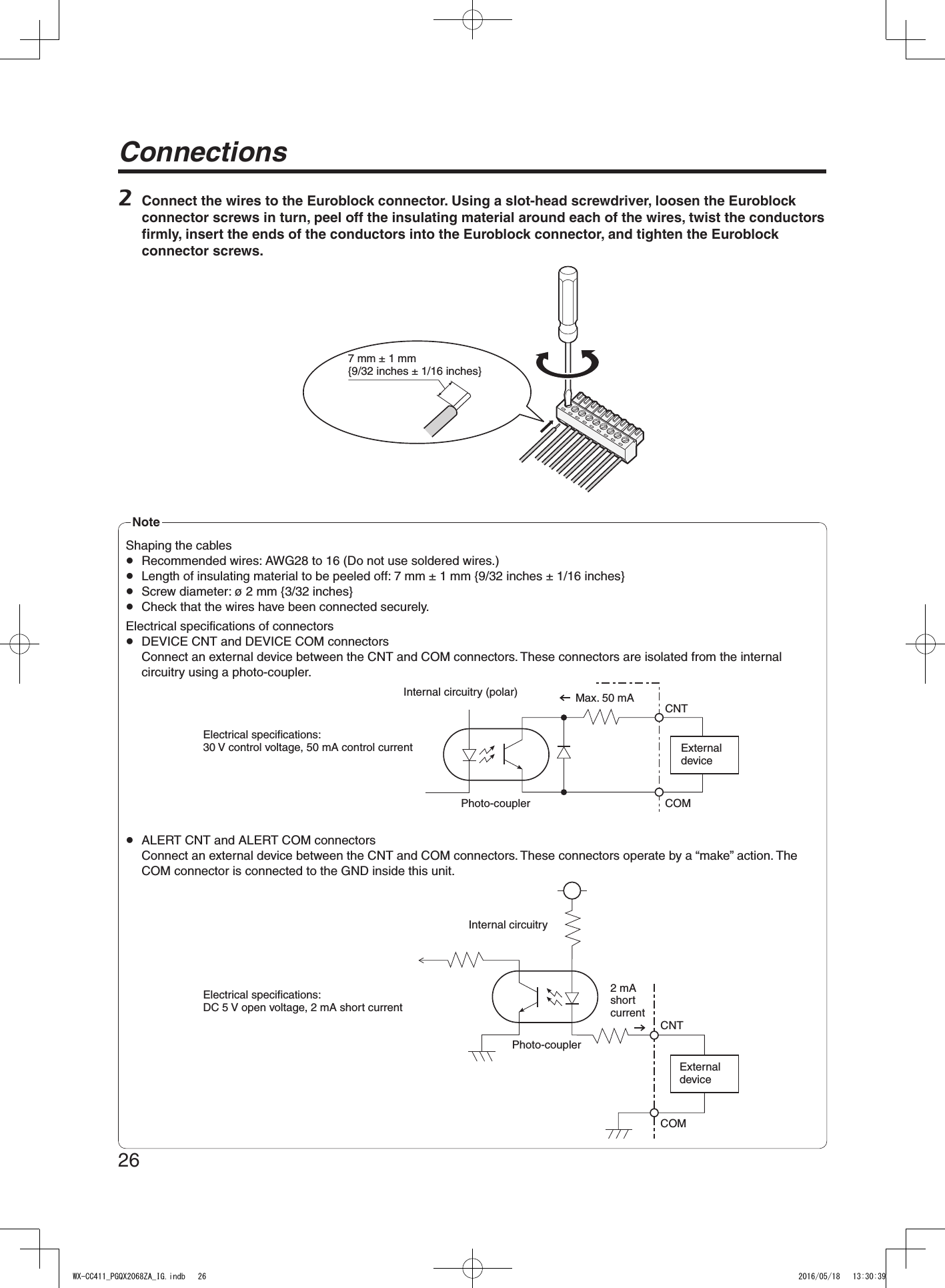
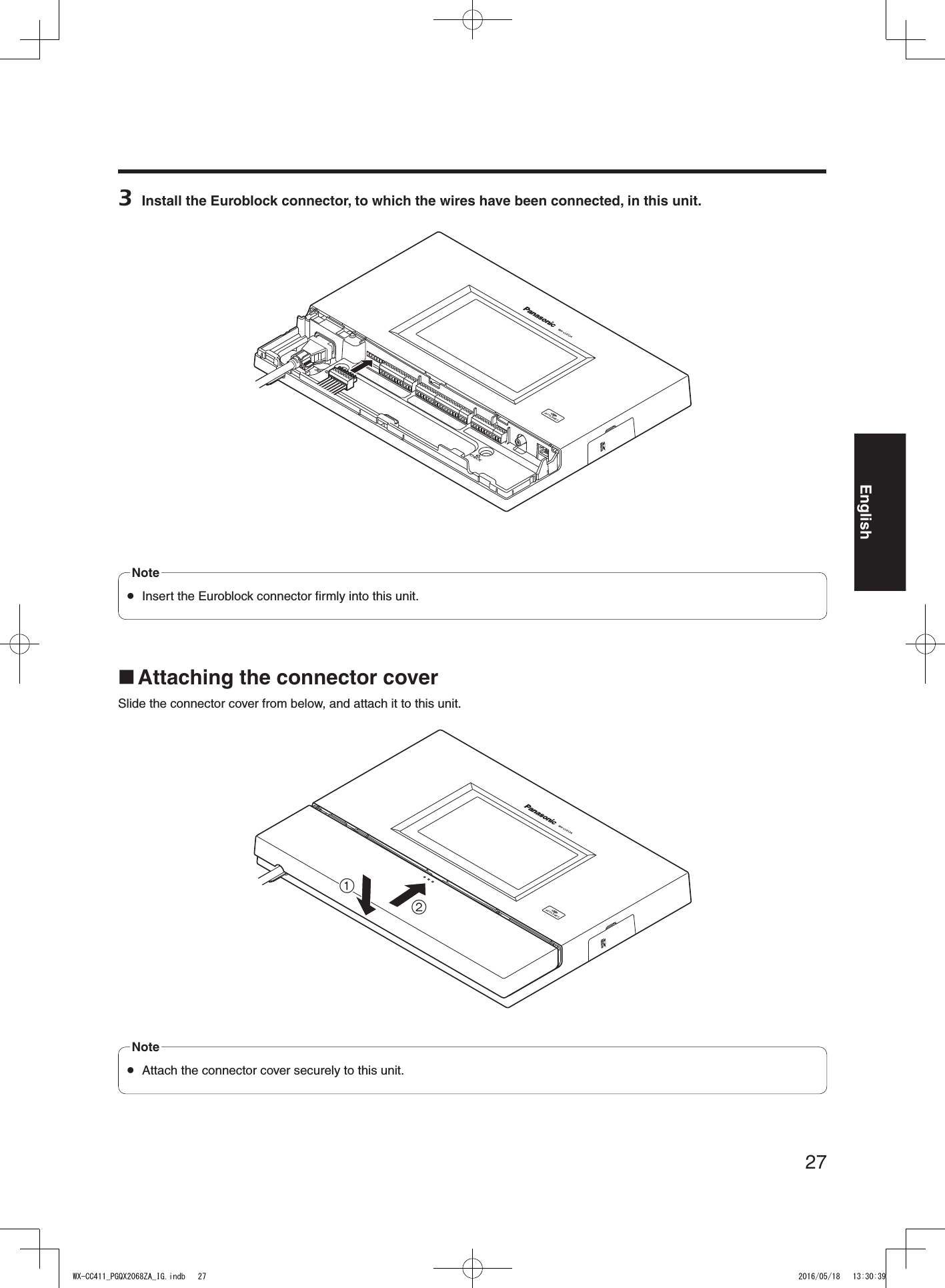
![13English External control output [DEVICE]This external control output is used for alerts.Using this unit’s settings, this connector is controlled in response to the reception of alert signals from the All-In-One Headsets or Belt Packs and to the signals from the alert input. Alert input [ALERT]This external input connector is used for alerts. It is connected to a sensor or other external device. Serial port [RS-232C]This port is for controlling the system from a personal computer. For details, contact the store where you purchased this unit. Video output [VIDEO OUT]This NTSC type of composite connector is for outputting camera images.For details, contact the store where you purchased this unit. Network port [10BASE-T/100BASE-TX]This is connected to a 10BASE-T or 100BASE-TX network, and it connects the Network Camera with the Center Module. Side panel Reset buttonPress this button using a fine-tipped object when this unit is not operating properly to restart this unit. SD card slotThis is where an SD card is inserted. SD card access LEDThis indicates the status of the SD card access. While the SD card is being accessed, it blinks in green. While the SD card access LED is blinking, do not eject the SD card, disconnect the power plug or press the reset button. Performing any of these actions may destroy the data on the card.ImportantWX-CC411_PGQX2068ZA_IG.indb 13 2016/05/18 13:30:26](https://usermanual.wiki/Panasonic-of-North-America/9TAWX-CC412A/User-Guide-3068481-Page-13.png)
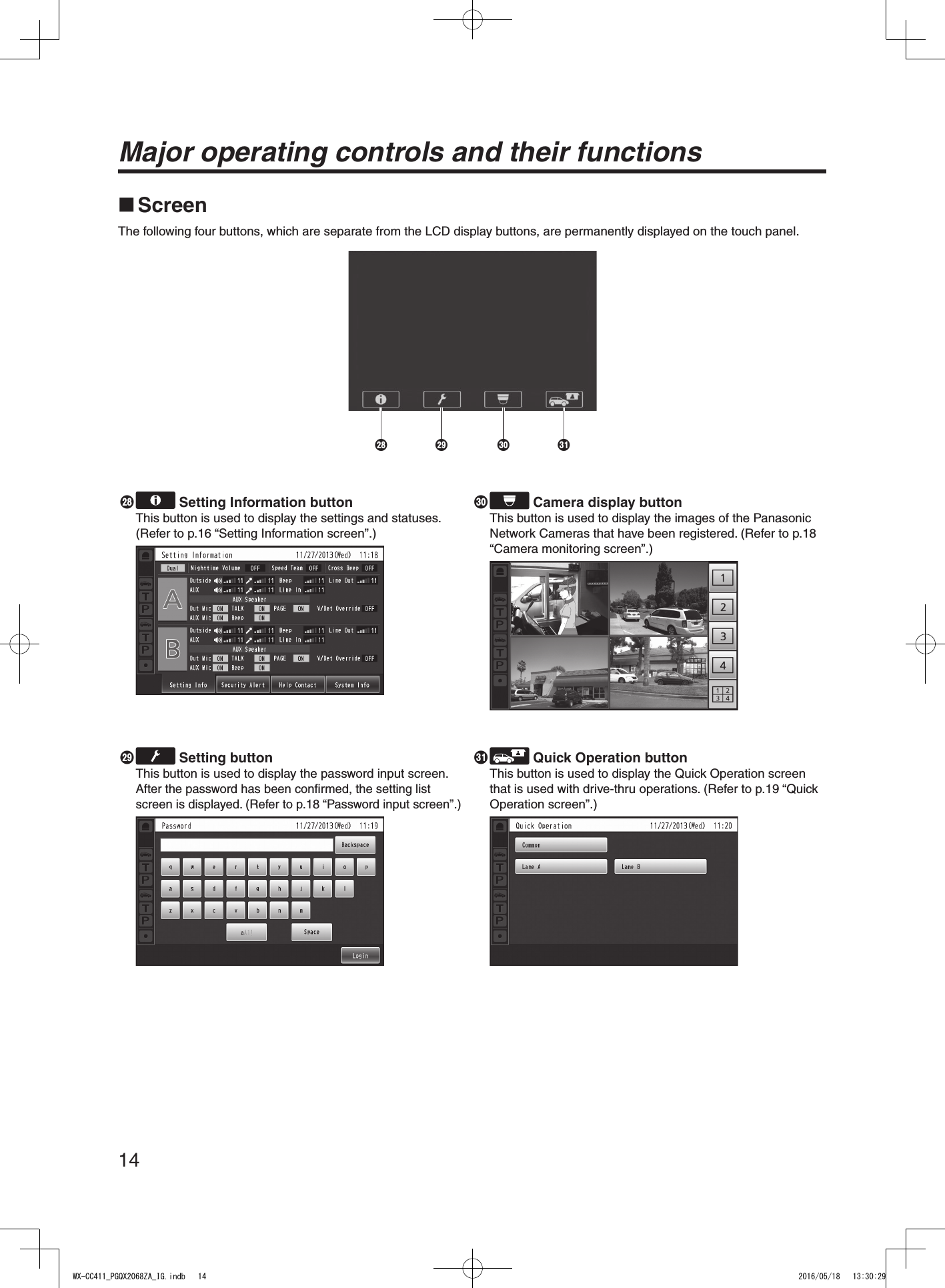
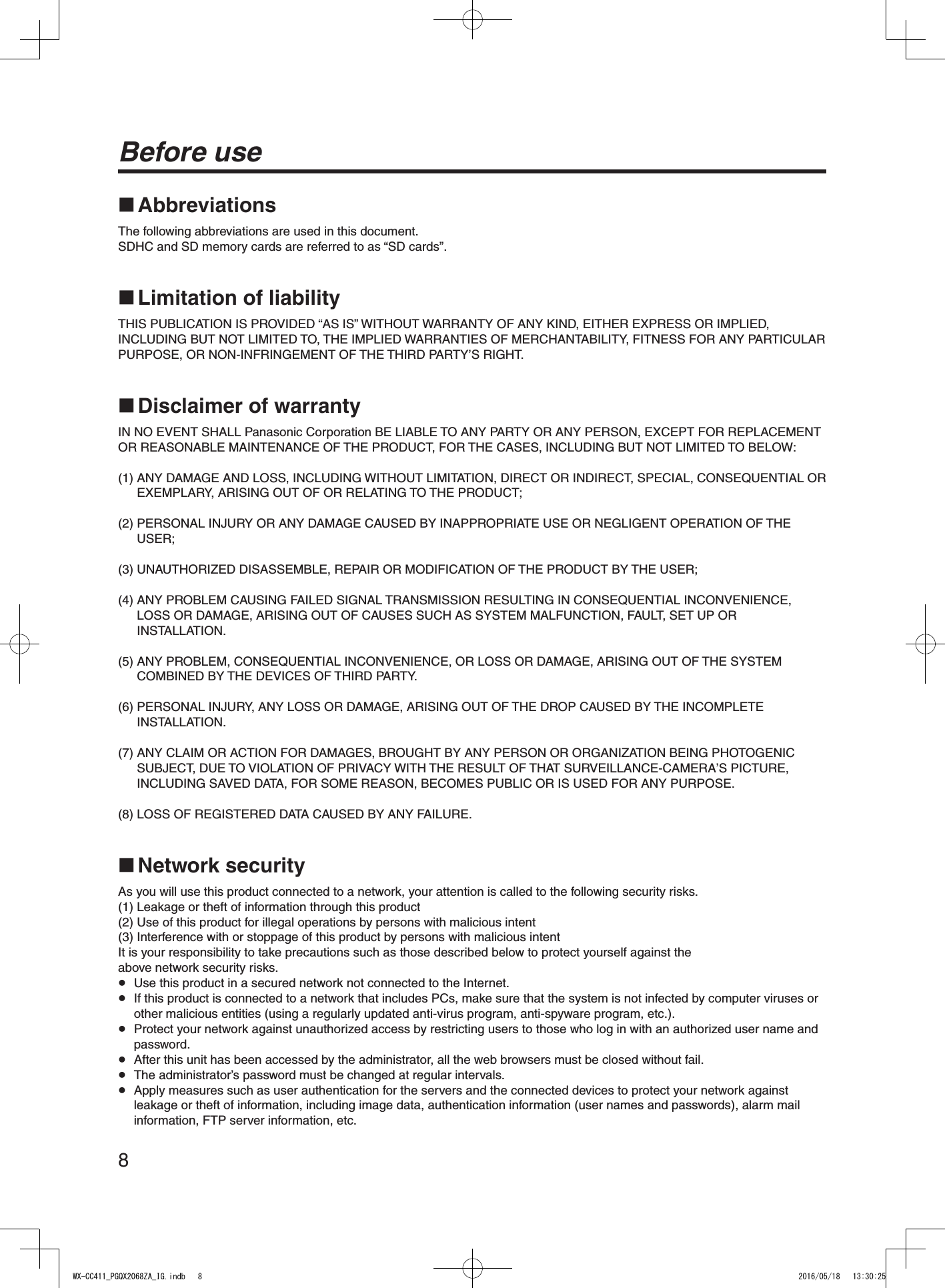
![16Description of screens Setting Information screenThe Setting Information screen appears when (Setting Information button) on the touch panel is touched. This unit’s settings and statuses can be confirmed on this screen. 1 2 3 41 Setting Info [Setting Info]When the Setting Info button is touched, the display on the LCD display switches to the setting list screen.2 Security Alert [Security Alert]When the Security Alert button is touched, the display on the LCD display switches to the Security Alert screen. (P.17)3 Help Contact [Help Contact]When the Help Contact button is touched, the display on the LCD display switches to the Help Contact screen. (P.18)4 System Information [System Info]When the System Info button is touched, the screen on the LCD display switches to the System Info screen. (P.18)Setting list screenThe setting list screen is displayed when the unit’s power is turned on or when the [Setting Info] button is touched.23 6 7 98 :4 51 1 Lane name display [A] ([B])The lane name is displayed. The lane setting statuses are displayed to the right of the lane name display.When the WX-CC412A is used, lane B is also displayed underneath lane A.2 Lane mode display [Single/Dual/Tandem]Lane mode that has been set is displayed.WX-CC411A: [Single] is displayed.WX-CC412A: [Dual] is displayed when the tandem lane setting is OFF, and [Tandem] is displayed when it is ON.3 Nighttime Volume display [Nighttime Volume ON/OFF/AUTO]The setting status of the volume of the order post speaker at night is displayed. The “Nighttime Volume” is a function that is used to adjust the volume level of the voice output from the order post speaker.Note4 Speed Team display [Speed Team ON/OFF]The status of the speed team operation is displayed. “Speed Team operation” refers to a mode of operation in which, at busy times when there are more vehicles than the lanes can accommodate, normal operation is suspended, the vehicle detectors are shut off, and the store personnel go directly to the customers in their vehicles to take their orders. Note5 Cross Beep display [Cross Beep ON/OFF]The Cross Beep status is displayed.This appears only when the WX-CC412A is used. “Cross Beep” is a function that sends the beep tone announcing the arrival of customers across the two lanes.Note6 Lane A order post speaker volume display [Outside]The volume level of the lane A order post speaker is displayed.7 Lane A kitchen speaker volume display [AUX]The volume level of the lane A kitchen speaker is displayed.WX-CC411_PGQX2068ZA_IG.indb 16 2016/05/18 13:30:31](https://usermanual.wiki/Panasonic-of-North-America/9TAWX-CC412A/User-Guide-3068481-Page-16.png)
![17English8 Lane A order post microphone volume display [Outside]The volume level of the lane A order post microphone is displayed.9 Lane A kitchen microphone volume display [AUX]The volume level of the lane A kitchen microphone is displayed.: Lane A beep tone volume display [Beep]The volume level of the lane A beep tone is displayed. Lane A line input volume display [Line In]The volume level of the lane A line input is displayed. Lane A line output volume display [Line Out]The volume level of the lane A line output is displayed. Lane A order post microphone ON/OFF display [Out Mic ON/OFF]The setting that determines whether to output the voice of the lane A order post microphone to the lane A kitchen speaker is displayed. Lane A kitchen microphone ON/OFF display [AUX Mic ON/OFF]The setting that determines whether to output the voice of the lane A kitchen microphone to the lane A kitchen speaker is displayed. Lane A talk ON/OFF display [TALK ON/OFF]The setting that determines whether to output the talk voice to the lane A kitchen speaker is displayed. “Talk” refers to communications between the customers and store personnel.Note Lane A beep tone ON/OFF display [Beep ON/OFF]The setting that determines whether to output the beep tone to the lane A kitchen speaker is displayed. Lane A paging ON/OFF display [PAGE ON/OFF]The lane A paging setting is displayed. “Paging” refers to communications among store personnel.Note Lane A V/Det Override ON/OFF display [V/Det Override ON/OFF]The status of the lane A V/Det Override is displayed. “V/Det Override” is a function that sets the vehicle detectors virtually to ON and keeps both the order post microphone and speaker in the ON setting.NoteSecurity Alert screenThe Security Alert screen appears when the [Security Alert] button on the Setting Information screen is touched.1 231 Cause and Initiation timeThe cause of a security alert that has occurred and the initiation time are displayed.[F Button] : Sent from the store personnel who have All-In-One Headsets or Belt Packs.[Alert 1 to 4] : Sent from alert input 1 to 4.2 Clear button [Clear]This is touched to forcibly clear the Security Alert.3 Stop button [Stop]This is touched when the Alert Message for the Security Alert is to be stopped.This appears when “Alert message playback” has been set for operations to be performed when a Security Alert has occurred.WX-CC411_PGQX2068ZA_IG.indb 17 2016/05/18 13:30:32](https://usermanual.wiki/Panasonic-of-North-America/9TAWX-CC412A/User-Guide-3068481-Page-17.png)
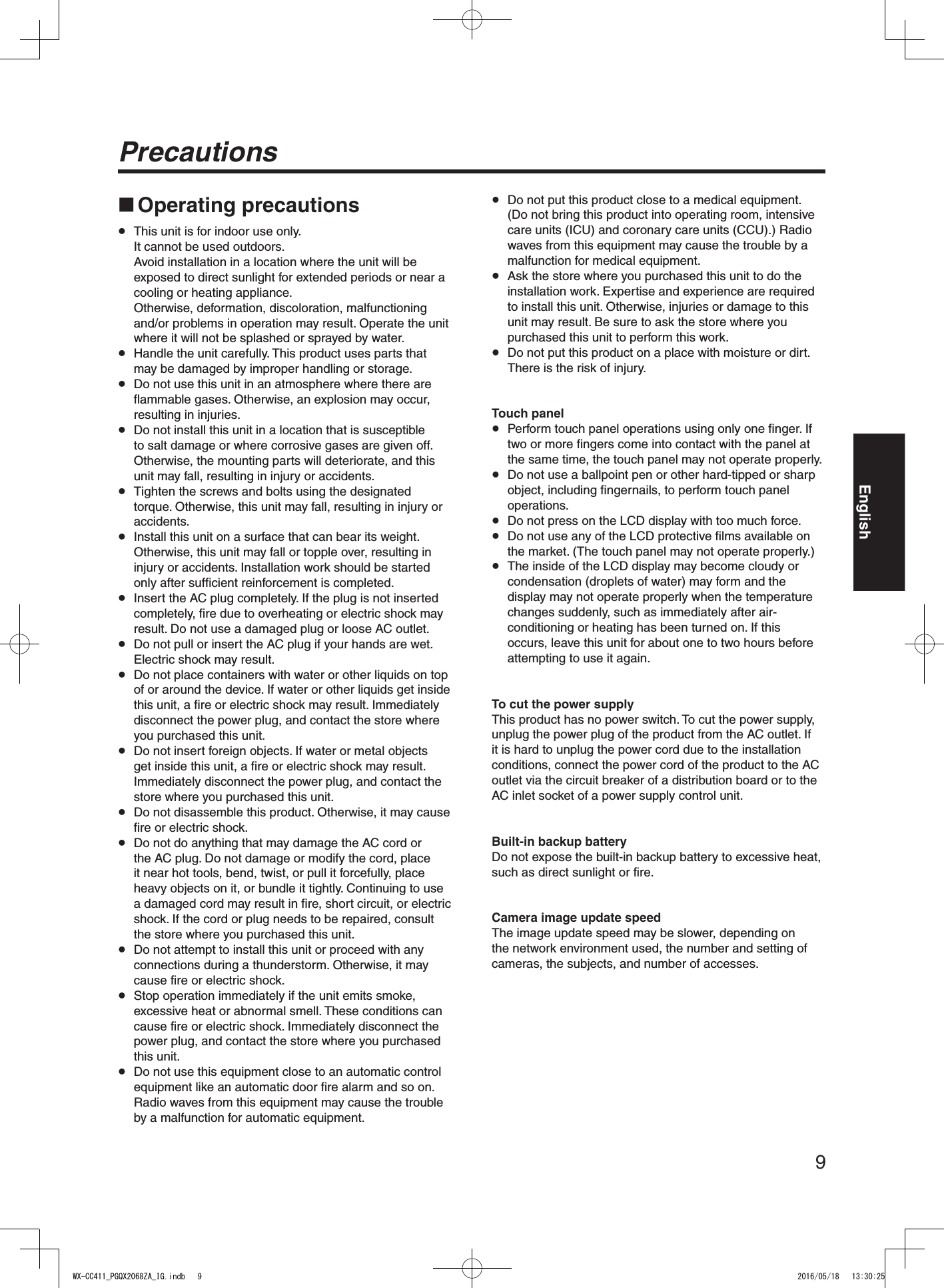
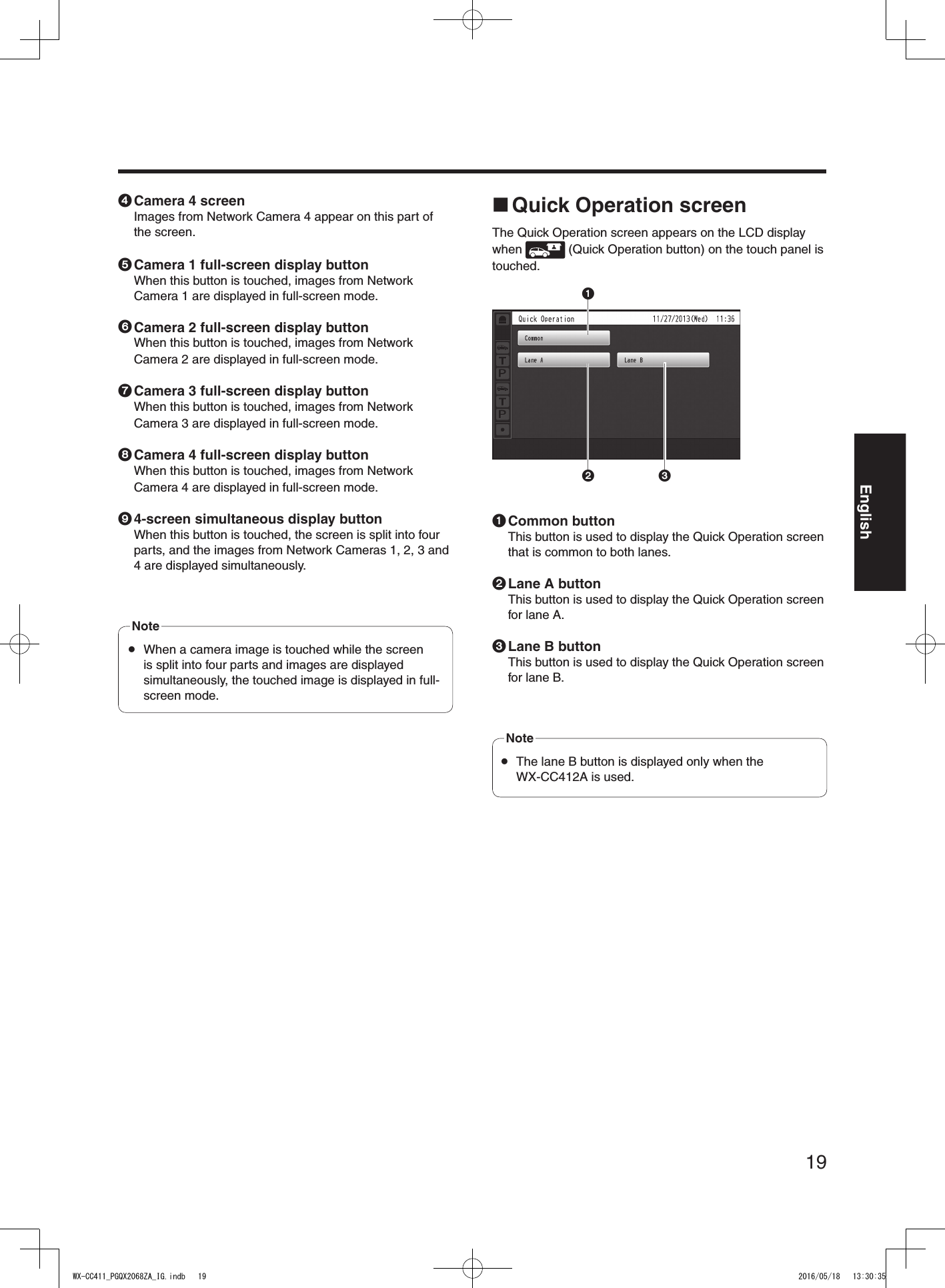
![18Description of screensHelp Contact screenThe Help Contact screen appears when the [Help Contact] button on the LCD display is touched.The emergency help contact is displayed on this screen. It can be set on the setting screen. If an email has been set using the browser ahead of time, an email can be sent from this screen. It is not possible to display the email send result even when, for instance, an email failed to be sent because the server was down or the wrong email was set. When installing this unit, check that emails can be correctly sent ahead of time.NoteSystem Info screenThe System Info screen appears when the [System Info] button on the LCD display is touched.Network statuses are shown on this screen. Password input screenThe password must be input for verification before operation moves to the setting screen.The password input screen appears when (setting button) on the touch panel is touched. For details on how to input the characters, refer to p.30 “Inputting characters”.Default password: 12345 Change the password at regular intervals for security purposes.Important Camera monitoring screenThe camera monitoring screen appears on the LCD display when (camera display button) on the touch panel is touched.1324567891 Camera 1 screenImages from Network Camera 1 appear on this part of the screen.2 Camera 2 screenImages from Network Camera 2 appear on this part of the screen.3 Camera 3 screenImages from Network Camera 3 appear on this part of the screen.WX-CC411_PGQX2068ZA_IG.indb 18 2016/05/18 13:30:35](https://usermanual.wiki/Panasonic-of-North-America/9TAWX-CC412A/User-Guide-3068481-Page-18.png)
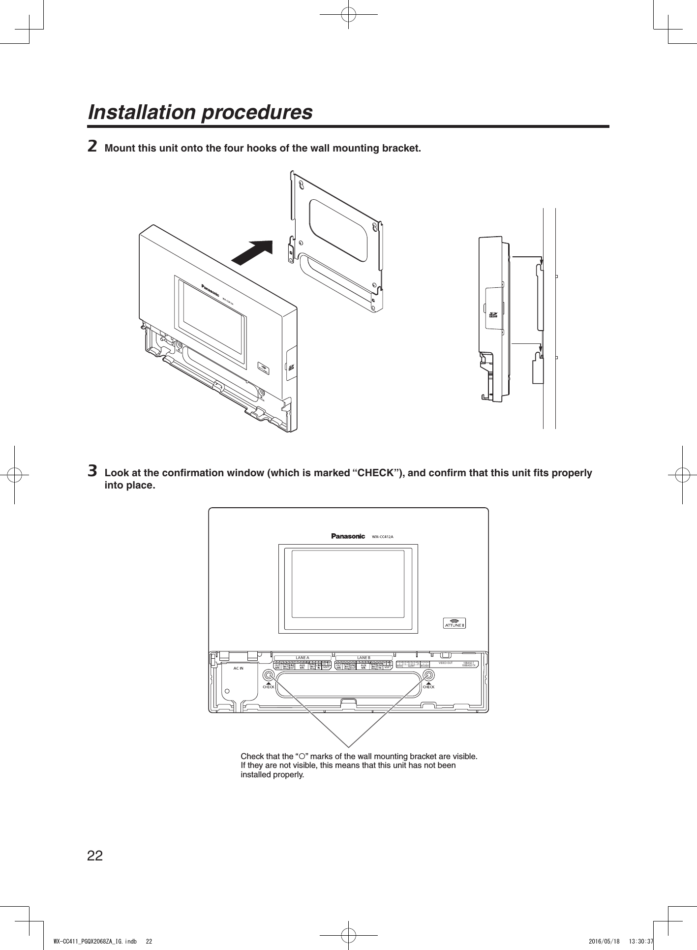
![21EnglishInstallation procedures Deciding on where to install the Center ModuleSelect a wall on which to mount this unit, drill a hole in it to pass the wires through, and decide where the four screws are to be positioned, as shown below.19013525402005 Ensure that the installation surface has the pull-out strength below.Important Installation1 Mount this unit using the accessory wall mounting bracket and 4 screws (4.1 mm × 25 mm {5/32 inches × 63/64 inches}). [Minimum pull-out strength: 780 N {80 kgf}]Screws (locally procured)(wood screws: 4.1 mm × 25 mm {5/32 inches × 63/64 inches})Wire channelWX-CC411_PGQX2068ZA_IG.indb 21 2016/05/18 13:30:37](https://usermanual.wiki/Panasonic-of-North-America/9TAWX-CC412A/User-Guide-3068481-Page-21.png)
![23English4 Use the accessory clamp to secure the power cord to the wall and attach the clamp using a screw (4.1 mm × 25 mm {5/32 inches × 63/64 inches}). [Minimum pull-out strength: 780 N {80 kgf}]150 mm to 200 mm{5-15/16 inches to 7-7/8 inches}Screw (locally procured)WX-CC411_PGQX2068ZA_IG.indb 23 2016/05/18 13:30:37](https://usermanual.wiki/Panasonic-of-North-America/9TAWX-CC412A/User-Guide-3068481-Page-23.png)
![29EnglishScreen operations Basic screen operationsThis section describes basic screen operations.For details on how to operate the unit and select its settings, refer to the “Operating Instructions <Setup Instructions>” (PDF file).2131 Return buttonThis button is used to return to the previous screen.2 Item selector buttonsOperation moves to the screen corresponding to the button that has been touched. On the setting screen, one of the buttons is selected (indicated in orange).The buttons have different names, depending on the situation.3 Page selector buttonsThese buttons are used to select the page when the screen extends over a multiple number of pages. When the ▼ button is touched, the next page screen is displayed, and when the ▲ button is touched, the previous page screen is displayed. The LCD display is easily scratched, so always perform the operations involving this display using one finger. Do not use a ballpoint pen or other hard-tipped or sharp object, including fingernails, to perform touch panel operations. Do not press on the LCD display with too much force. Do not use any of the LCD protective films available on the market. (The touch panel may not operate properly.) The inside of the LCD display may become cloudy or condensation (droplets of water) may form and the display may not operate properly when the temperature changes suddenly, such as immediately after air-conditioning or heating has been turned on. If this occurs, leave this unit for about one to two hours before attempting to use it again.Note Entering the settingsOn a screen with multiple setting items, touch the [Set] button to confirm a setting.11 Set buttonThis button confirms all multiple settings displayed on the screen together.WX-CC411_PGQX2068ZA_IG.indb 29 2016/05/18 13:30:41](https://usermanual.wiki/Panasonic-of-North-America/9TAWX-CC412A/User-Guide-3068481-Page-29.png)
![30Screen operations Inputting charactersUse the keys on the keyboard to input the characters when a password or an address is to be input.1243561 Input character display areaThe characters that have been input are displayed.2 Backspace buttonTouch this button to delete the last character of the characters shown in the input character display area.3 Character input buttonsThe character on the button that is touched is input.4 Space buttonTouch this button to input a space.5 Set/Enter button [Enter/Login]Touch this button to enter the character string that has been input.6 Character type selector buttonTouch this button to change the type of characters that are to be input. Inputting the date and timeInput the date and time by using the [+] and [-] buttons.2 311 Setting value display areaThe current setting values are displayed.2 + and – buttonsAdjust the settings by touching the + and – buttons.3 Set/Enter button [Set/Enter]Touch this button to enter the date and time that has been set. Adjusting the volume levelAdjust the volume level.2 1 21 Volume level display areaThe current volume levels are displayed.2 + and – buttonsAdjust the levels by touching the + and – buttons. Changes in the volume level take place in real time.WX-CC411_PGQX2068ZA_IG.indb 30 2016/05/18 13:30:43](https://usermanual.wiki/Panasonic-of-North-America/9TAWX-CC412A/User-Guide-3068481-Page-30.png)
![31EnglishOperating procedures Basic operationsTALK: Talking with the customersThis function enables two-way conversations between the store personnel who are wearing All-In-One Headsets or Belt Packs and the customer at the order post.For further details on conversation methods, refer to the Operating Instructions for the Belt Pack (WX-CT420) or All-In-One Headset (WX-CH450).PAGE: Talking with other store personnelStore personnel who are wearing All-In-One Headsets or Belt Packs can talk to one another without being heard by customers.For further details on paging methods, refer to the Operating Instructions for the Belt Pack (WX-CT420) or All-In-One Headset (WX-CH450).Dual drive-thru lane changeover (WX-CC412A only)In the case of a dual drive-thru, it is possible to talk or page by selecting lane A or lane B.For details on how to perform lane changeover operation, refer to the Operating Instructions for the Belt Pack (WX-CT420) or All-In-One Headset (WX-CH450). ID Registration To talk or page using an All-In-One Headset or Belt Pack, its ID must be registered. For ID registration, set the Center Module to ID registration mode, and proceed with the registration by operating the All-In-One Headset or Belt Pack concerned.The ID registration procedure is described below based on an example involving an All-In-One Headset or Belt Pack operation.1 Touch (setting button) on the touch panel. The password input screen appears.2 Input the password, and touch the [Login] button.Default password: 12345 Change the password at regular intervals for security purposes.Important The setting menu is displayed.WX-CC411_PGQX2068ZA_IG.indb 31 2016/05/18 13:30:44](https://usermanual.wiki/Panasonic-of-North-America/9TAWX-CC412A/User-Guide-3068481-Page-31.png)
![32Operating procedures3 Touch [Headsets] button, and then the [ID Registration] button. The ID registration screen appears. The registered All-In-One Headset or Belt Pack numbers are displayed in the [Registered Headsets] area. When ID registration is completed successfully, the ID of the newly registered All-In-One Headset or Belt Pack is added.Note4 Touch the [Start] button. The following pop-up screen is displayed. You cannot perform other operations during ID registration. To continue ID registration, touch the [YES] button. To stop ID registration, touch the [NO] button. Touch the [YES] button to start ID registration mode.The number of the All-In-One Headset or Belt Pack that has been registered is displayed.5 Press the [POWER] button while holding down the [T1] button and [T2] button of the All-In-One Headset or Belt Pack. The All-In-One Headset or Belt Pack starts up in ID registration mode. The “Registration Mode” voice prompt will be heard from the earphone, and the power indicator will blink orange. In ID registration mode, the buttons and indicators have different functions from those at normal startup.6 Press the [T1] button on the All-In-One Headset or Belt Pack. The All-In-One Headset or Belt Pack searches for a Center Module that is in ID registration mode. The “Connecting center module A” voice prompt will be heard from the earphone, and the lane indicator will blink orange. In the case of the WX-CC412A, after lane A registration, the “Connecting center module B” voice prompt will be heard, and the lane indicator will blink green. When ID registration has been completed successfully, the “Registration complete” voice prompt will be heard from the earphone, and then a voice prompt for the number of the registered All-In-One Headset or Belt Pack will be heard. The power indicator and the lane indicator now stop blinking, and light up.After registrating all of the headset IDs, touch the [Stop] button on the ID registration screen.ID registration mode for the Center Module is exited. The power indicator of the All-In-One Headset or Belt Pack changes from orange to green. When registering the IDs of a multiple number of All-In-One Headsets or Belt Packs, register the ID of each unit in sequence. If an attempt is made to register the IDs of multiple units at the same time, the IDs may not be registered correctly. During the ID registration process, do not turn off the power of the All-In-One Headsets or Belt Packs or remove their batteries. Otherwise, their IDs may not be registered correctly. If the registration is not proceeding smoothly, touch the [Stop] button on the Center Module, exit ID registration mode, and then try again. When ID registration fails, a “BUU-UU-UU” warning sounds in the All-In-One Headset or Belt Pack concerned, and then the “Failed” voice prompt is heard. If an ID registration has failed, the ID of the All-In-One Headset or Belt Pack will not be registered in the Center Module, and the power indicator of the All-In-One Headset or Belt Pack concerned will blink in red. The IDs of up to 32 All-In-One Headsets or Belt Packs can be registered in one Center Module. If an attempt is made to register IDs for more than 32 units, the IDs of the headsets not used for the longest time will be automatically deleted, and then the IDs of the new units will be registered. It is not possible to register the ID of a wireless repeater while ID registration mode of the All-In-One Headsets or Belt Packs is active.ImportantWX-CC411_PGQX2068ZA_IG.indb 32 2016/05/18 13:30:46](https://usermanual.wiki/Panasonic-of-North-America/9TAWX-CC412A/User-Guide-3068481-Page-32.png)
![33English Convenient Functions (Other Functions)Auto-TALK-LockThis function enables the All-In-One Headset or Belt Pack of pre-determined store personnel to automatically enter talk mode when a customer approaches the order post. (Talk-Lock mode) For details on how to set Auto-Talk-Lock mode, refer to the Operating Instructions for the Belt Pack (WX-CT420) or All-In-One Headset (WX-CH450).Manager modeOne of all the All-In-One Headsets or Belt Packs in a lane can be set to manager mode.The All-In-One Headset or Belt Pack in manager mode has a higher priority than the other All-In-One Headsets or Belt Packs, and can monopolize one of the four communication channels.This means that the manager can talk or page at any time.For details on how to set manager mode, refer to the Operating Instructions for the Belt Pack (WX-CT420) or All-In-One Headset (WX-CH450).Speed Team“Speed Team operation” refers to a mode of operation in which, at busy times when there are more vehicles than the lanes can accommodate, normal operation is suspended, the vehicle detectors are shut off, and the store personnel go directly to the customers in their vehicles to take their orders.1 Touch (Quick Operation button) on the touch panel, and then the [Common] button. 2 Touch the [ON] button for [Speed Team] to enable Speed Team operation. In the All-In-One Headsets or Belt Packs, the “SPEED TEAM ON” voice prompt is heard from the earphones. In Speed Team mode, the “SPEED TEAM ON” voice prompt will be heard every 5 minutes from the earphone of the All-In-One Headsets or Belt Packs.Note3 When the [P] button of the All-In-One Headset or Belt Pack is pressed, conversation becomes possible in page lock mode. Even if the [P] button is set to Press-to-Page, the button will still operate in page lock. For further details on paging methods, refer to the Operating Instructions for the Belt Pack (WX-CT420) or All-In-One Headset (WX-CH450).WX-CC411_PGQX2068ZA_IG.indb 33 2016/05/18 13:30:46](https://usermanual.wiki/Panasonic-of-North-America/9TAWX-CC412A/User-Guide-3068481-Page-33.png)
![34Operating procedures4 To release Speed Team operation, touch the [OFF] button for [Speed Team] on the screen in step 2. In the All-In-One Headsets or Belt Packs, the “SPEED TEAM OFF” voice prompt is heard from the earphones, and normal operation is restored. In Speed Team mode, it is not possible to talk with customers at the order posts. When talking is attempted from an All-In-One Headset or Belt Pack, the “Operation not allowed” voice prompt is heard from the earphone.NoteCross Beep (WX-CC412A only)“Cross Beep” is a function that enables a beep tone to be heard from the All-In-One Headsets or Belt Packs when a customer approaches the order post of the other lane.1 Touch (Quick Operation button) on the touch panel, and then touch the [Common] button. 2 Touch the [ON] button for [Cross Beep] to enable Cross Beep operation. To release Cross Beep, touch the [OFF] button.OFF: If lane A has been selected, beep tone A will be heard when a vehicle in lane A is detected.However, beep tone B will not be heard even when a vehicle in lane B has been detected.ON:If lane A has been selected, beep tone A will be heard when a vehicle in lane A is detected.Furthermore, beep tone B is heard at a low volume level even when a vehicle in lane B has been detected.When vehicles have been detected in both lanes, beep tone A and beep tone B, which are heard at a low volume level, will be heard alternately.Cross BeepVehicle detector All-In-One Headset or Belt Pack Lane A is ON Lane B is ON A BOFF¡–Beep A––¡–Beep B¡ ¡Beep A Beep BON¡–Beep A Low level Beep A–¡Low level Beep B Beep B¡ ¡Beep A + Low level Beep B Beep B + Low level Beep AWX-CC411_PGQX2068ZA_IG.indb 34 2016/05/18 13:30:47](https://usermanual.wiki/Panasonic-of-North-America/9TAWX-CC412A/User-Guide-3068481-Page-34.png)
![35EnglishV/Det Override“V/Det Override” is a function that sets the vehicle detectors virtually to ON and keeps both the order post microphone and speaker in the ON setting.1 Touch (Quick Operation button) on the touch panel, and then touch the [Lane A/B] button*. * [Lane B] button appears only when the WX-CC412A is used.2 Touch the [ON] button for [V/Det Override] to enable this function. To release V/Det Override, touch the [OFF] button.OFF:When the vehicle detector detects a vehicle at the order post, a beep tone is heard from the earphone.When the Talk button on an All-In-One Headset or Belt Pack is pressed, the order post’s speaker and microphone are turned on.When the vehicle drives off, vehicle detection is turned off. The OFF setting and Auto-Talk-Lock mode can now be established.ON:When [V/Det Override] is set to ON, the order post’s microphone is turned on permanently and talking is enabled even when the vehicle detector is not ON. (Sound from the order post’s microphone can be forcibly heard.) When Speed Team is enabled, the setting for V/Det Override is automatically turned OFF. In Speed Team mode, you cannot change the setting for V/Det Override.NoteTalk/page releaseThe talk (or page) status of an All-In-One Headset or Belt Pack is forcibly released.1 Touch (Quick Operation button) on the touch panel, and then touch the [Lane A/B] button*.* [Lane B] button appears only when the WX-CC412A is used.2 Touch the [Execute] button for [T/P Release]. Communication is forcibly terminated. The talk (or page) status of the All-In-One Headset or Belt Pack in manager mode is not released.NoteWX-CC411_PGQX2068ZA_IG.indb 35 2016/05/18 13:30:48](https://usermanual.wiki/Panasonic-of-North-America/9TAWX-CC412A/User-Guide-3068481-Page-35.png)

![43EnglishTHIS SOFTWARE IS PROVIDED BY ERIC YOUNG ''AS IS'' AND ANY EXPRESS OR IMPLIED WARRANTIES, INCLUDING, BUT NOT LIMITED TO, THE IMPLIED WARRANTIES OF MERCHANTABILITY AND FITNESS FOR A PARTICULAR PURPOSE ARE DISCLAIMED. IN NO EVENT SHALL THE AUTHOR OR CONTRIBUTORS BE LIABLE FOR ANY DIRECT, INDIRECT, INCIDENTAL, SPECIAL, EXEMPLARY, OR CONSEQUENTIAL DAMAGES (INCLUDING, BUT NOT LIMITED TO, PROCUREMENT OF SUBSTITUTE GOODS OR SERVICES; LOSS OF USE, DATA, OR PROFITS; OR BUSINESS INTERRUPTION)HOWEVER CAUSED AND ON ANY THEORY OF LIABILITY, WHETHER IN CONTRACT, STRICT LIABILITY, OR TORT (INCLUDING NEGLIGENCE OR OTHERWISE) ARISING IN ANY WAY OUT OF THE USE OF THIS SOFTWARE, EVEN IF ADVISED OF THE POSSIBILITY OF SUCH DAMAGE.The licence and distribution terms for any publically available version or derivative of this code cannot be changed. i.e. this code cannot simply be copied and put under another distribution licence [including the GNU Public Licence.]<md5.h>Copyright (C) 1995-1998 Eric Young (eay@cryptsoft.com) All rights reserved. This package is an SSL implementation written by Eric Young (eay@cryptsoft.com).The implementation was written so as to conform with Netscapes SSL. This library is free for commercial and non-commercial use as long as the following conditions are aheared to. The following conditions apply to all code found in this distribution, be it the RC4, RSA, lhash, DES, etc., code; not just the SSL code. The SSL documentation included with this distribution is covered by the same copyright terms except that the holder is Tim Hudson (tjh@cryptsoft.com).Copyright remains Eric Young's, and as such any Copyright notices in the code are not to be removed.If this package is used in a product, Eric Young should be given attribution as the author of the parts of the library used.This can be in the form of a textual message at program startup or in documentation (online or textual) provided with the package.Redistribution and use in source and binary forms, with or without modification, are permitted provided that the following conditions are met:1. Redistributions of source code must retain the copyright notice, this list of conditions and the following disclaimer. 2. Redistributions in binary form must reproduce the above copyright notice, this list of conditions and the following disclaimer in the documentation and/or other materials provided with the distribution. 3. All advertising materials mentioning features or use of this software must display the following acknowledgement: "This product includes cryptographic software written by Eric Young (eay@cryptsoft.com)" The word 'cryptographic' can be left out if the rouines from the library being used are not cryptographic related :-).4. If you include any Windows specific code (or a derivative thereof) from the apps directory (application code) you must include an acknowledgement: "This product includes software written by Tim Hudson (tjh@cryptsoft.com)"THIS SOFTWARE IS PROVIDED BY ERIC YOUNG ''AS IS'' AND ANY EXPRESS OR IMPLIED WARRANTIES, INCLUDING, BUT NOT LIMITED TO, THE IMPLIED WARRANTIES OF MERCHANTABILITY AND FITNESS FOR A PARTICULAR PURPOSE ARE DISCLAIMED. IN NO EVENT SHALL THE AUTHOR OR CONTRIBUTORS BE LIABLE FOR ANY DIRECT, INDIRECT, INCIDENTAL, SPECIAL, EXEMPLARY, OR CONSEQUENTIAL DAMAGES (INCLUDING, BUT NOT LIMITED TO, PROCUREMENT OF SUBSTITUTE GOODS OR SERVICES; LOSS OF USE, DATA, OR PROFITS; OR BUSINESS INTERRUPTION)HOWEVER CAUSED AND ON ANY THEORY OF LIABILITY, WHETHER IN CONTRACT, STRICT LIABILITY, OR TORT (INCLUDING NEGLIGENCE OR OTHERWISE) ARISING IN ANY WAY OUT OF THE USE OF THIS SOFTWARE, EVEN IF ADVISED OF THE POSSIBILITY OF SUCH DAMAGE.The licence and distribution terms for any publically available version or derivative of this code cannot be changed. i.e. this code cannot simply be copied and put under another distribution licence [including the GNU Public Licence.]<md5_dgst.c>Copyright (C) 1995-1998 Eric Young (eay@cryptsoft.com) All rights reserved.This package is an SSL implementation written by Eric Young (eay@cryptsoft.com).The implementation was written so as to conform with Netscapes SSL. This library is free for commercial and non-commercial use as long as the following conditions are aheared to. The following conditions apply to all code found in this distribution, be it the RC4, RSA, lhash, DES, etc., code; not just the SSL code. The SSL documentation included with this distribution is covered by the same copyright terms except that the holder is Tim Hudson (tjh@cryptsoft.com).WX-CC411_PGQX2068ZA_IG.indb 43 2016/05/18 13:30:48](https://usermanual.wiki/Panasonic-of-North-America/9TAWX-CC412A/User-Guide-3068481-Page-43.png)
![44Copyright remains Eric Young's, and as such any Copyright notices in the code are not to be removed.If this package is used in a product, Eric Young should be given attribution as the author of the parts of the library used.This can be in the form of a textual message at program startup or in documentation (online or textual) provided with the package.Redistribution and use in source and binary forms, with or without modification, are permitted provided that the following conditions are met:1. Redistributions of source code must retain the copyright notice, this list of conditions and the following disclaimer. 2. Redistributions in binary form must reproduce the above copyright notice, this list of conditions and the following disclaimer in the documentation and/or other materials provided with the distribution. 3. All advertising materials mentioning features or use of this software must display the following acknowledgement: "This product includes cryptographic software written by Eric Young (eay@cryptsoft.com)" The word 'cryptographic' can be left out if the rouines from the library being used are not cryptographic related :-). 4. If you include any Windows specific code (or a derivative thereof) from the apps directory (application code) you must include an acknowledgement: "This product includes software written by Tim Hudson (tjh@cryptsoft.com)" THIS SOFTWARE IS PROVIDED BY ERIC YOUNG ''AS IS'' AND ANY EXPRESS OR IMPLIED WARRANTIES, INCLUDING, BUT NOT LIMITED TO, THE IMPLIED WARRANTIES OF MERCHANTABILITY AND FITNESS FOR A PARTICULAR PURPOSE ARE DISCLAIMED. IN NO EVENT SHALL THE AUTHOR OR CONTRIBUTORS BE LIABLE FOR ANY DIRECT, INDIRECT, INCIDENTAL, SPECIAL, EXEMPLARY, OR CONSEQUENTIAL DAMAGES (INCLUDING, BUT NOT LIMITED TO, PROCUREMENT OF SUBSTITUTE GOODS OR SERVICES; LOSS OF USE, DATA, OR PROFITS; OR BUSINESS INTERRUPTION)HOWEVER CAUSED AND ON ANY THEORY OF LIABILITY, WHETHER IN CONTRACT, STRICT LIABILITY, OR TORT (INCLUDING NEGLIGENCE OR OTHERWISE) ARISING IN ANY WAY OUT OF THE USE OF THIS SOFTWARE, EVEN IF ADVISED OF THE POSSIBILITY OF SUCH DAMAGE.The licence and distribution terms for any publically available version or derivative of this code cannot be changed. i.e. this code cannot simply be copied and put under another distribution licence [including the GNU Public Licence.]<e_os2.h>Copyright (c) 1998-2000 The OpenSSL Project. All rights reserved.Redistribution and use in source and binary forms, with or without modification, are permitted provided that the following conditions are met:1. Redistributions of source code must retain the above copyright notice, this list of conditions and the following disclaimer. 2. Redistributions in binary form must reproduce the above copyright notice, this list of conditions and the following disclaimer in the documentation and/or other materials provided with the distribution. 3. All advertising materials mentioning features or use of this software must display the following acknowledgment: "This product includes software developed by the OpenSSL Project for use in the OpenSSL Toolkit. (http://www.openssl.org/)"4. The names "OpenSSL Toolkit" and "OpenSSL Project" must not be used to endorse or promote products derived from this software without prior written permission. For written permission, please contact openssl-core@openssl.org. 5. Products derived from this software may not be called "OpenSSL" nor may "OpenSSL" appear in their names without prior written permission of the OpenSSL Project. 6. Redistributions of any form whatsoever must retain the following acknowledgment: "This product includes software developed by the OpenSSL Project for use in the OpenSSL Toolkit (http://www.openssl.org/)" THIS SOFTWARE IS PROVIDED BY THE OpenSSL PROJECT ''AS IS'' AND ANY EXPRESSED OR IMPLIED WARRANTIES, INCLUDING, BUT NOT LIMITED TO, THE IMPLIED WARRANTIES OF MERCHANTABILITY AND FITNESS FOR A PARTICULAR PURPOSE ARE DISCLAIMED. IN NO EVENT SHALL THE OpenSSL PROJECT OR ITS CONTRIBUTORS BE LIABLE FOR ANY DIRECT, INDIRECT, INCIDENTAL, SPECIAL, EXEMPLARY, OR CONSEQUENTIAL DAMAGES (INCLUDING, BUT NOT LIMITED TO, PROCUREMENT OF SUBSTITUTE GOODS OR SERVICES; LOSS OF USE, DATA, OR PROFITS; OR BUSINESS INTERRUPTION)HOWEVER CAUSED AND ON ANY THEORY OF LIABILITY, WHETHER IN CONTRACT, STRICT LIABILITY, OR TORT (INCLUDING NEGLIGENCE OR OTHERWISE) ARISING IN ANY WAY OUT OF THE USE OF THIS SOFTWARE, EVEN IF ADVISED OF THE POSSIBILITY OF SUCH DAMAGE.This product includes cryptographic software written by Eric Young (eay@cryptsoft.com). This product includes software written by Tim Hudson (tjh@cryptsoft.com). LicensesWX-CC411_PGQX2068ZA_IG.indb 44 2016/05/18 13:30:48](https://usermanual.wiki/Panasonic-of-North-America/9TAWX-CC412A/User-Guide-3068481-Page-44.png)
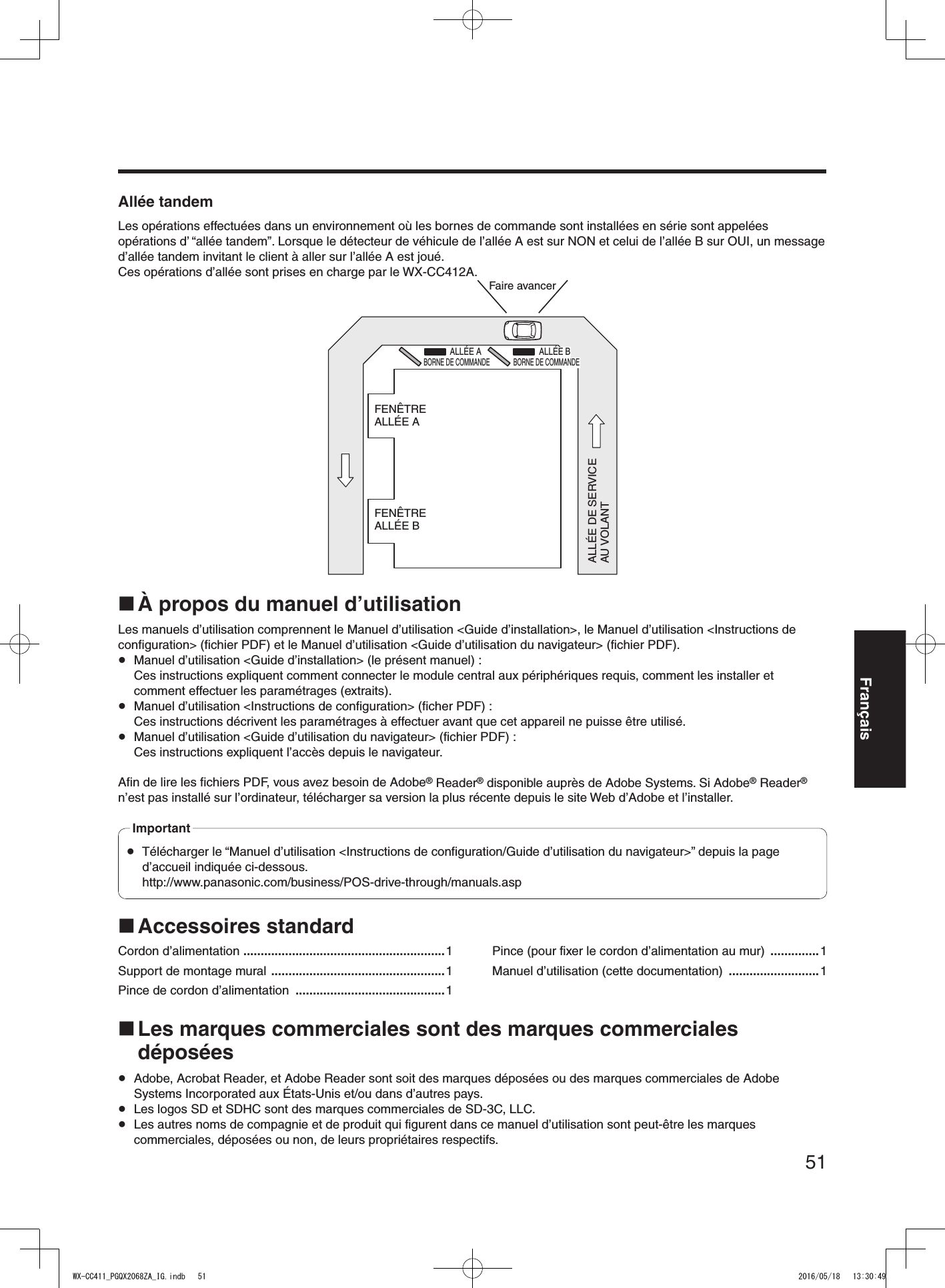
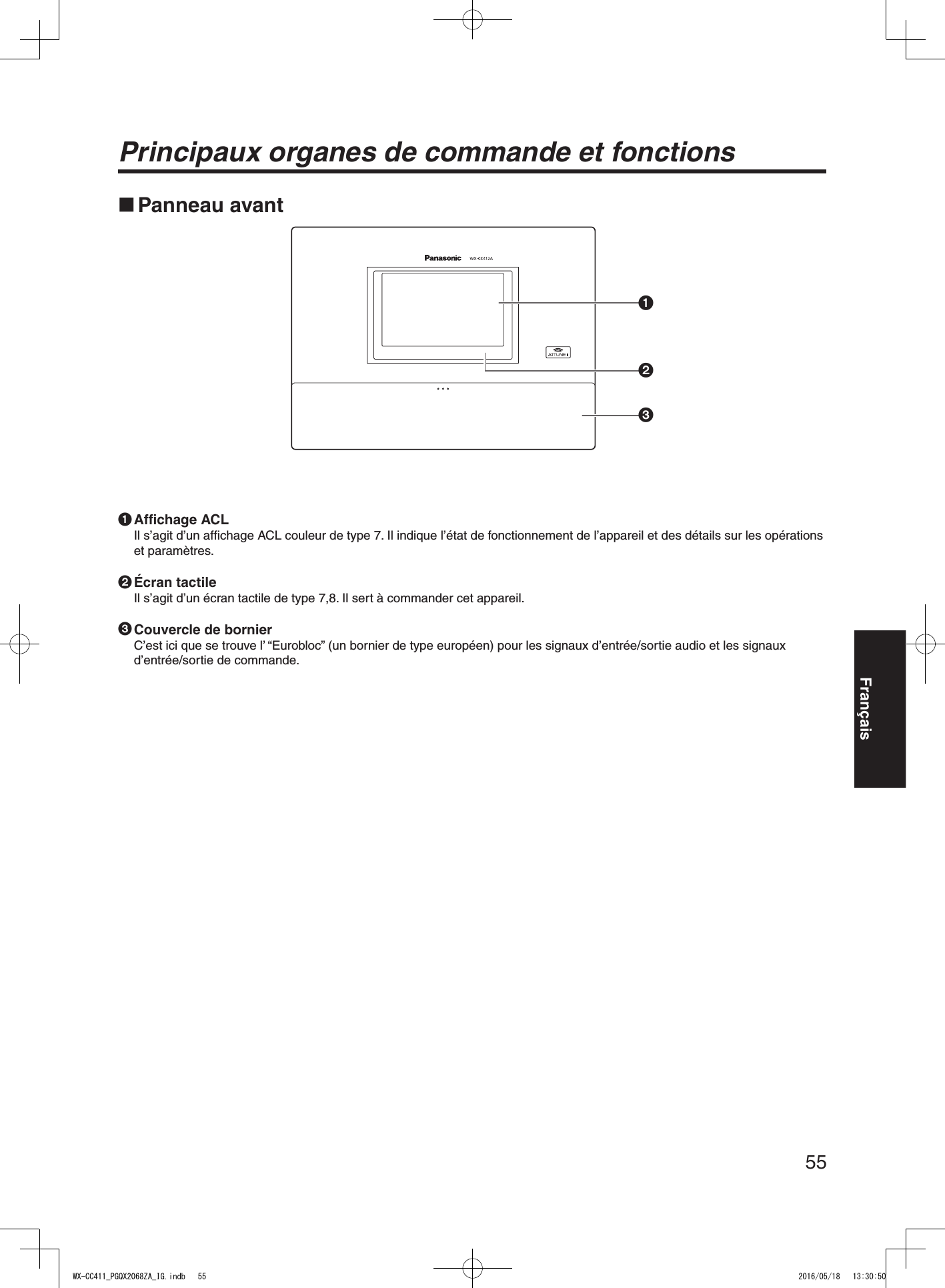
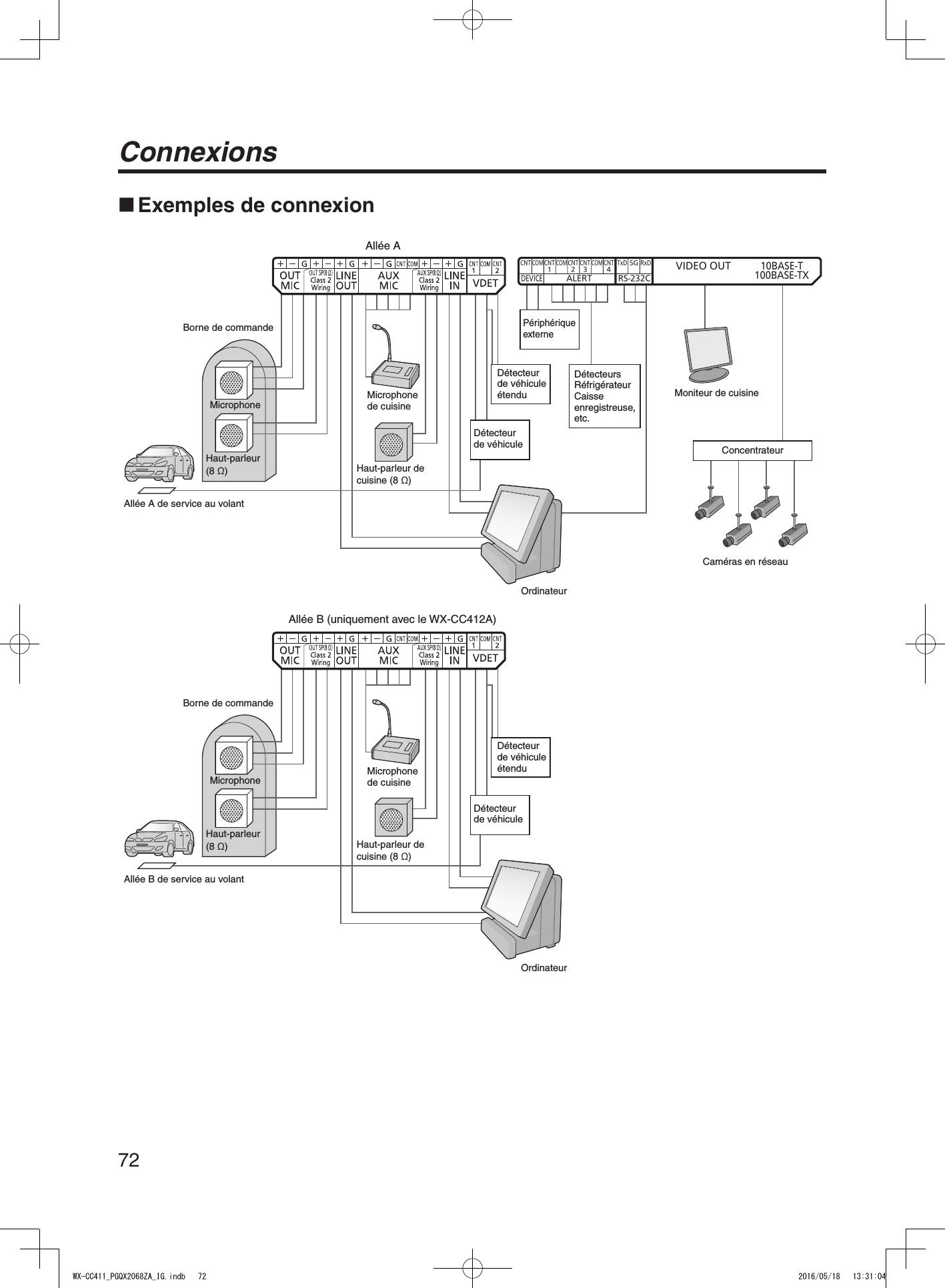
![56Principaux organes de commande et fonctions BornierCNT1COMLANE A LANE BCNTDEVICEALERT RS-232CVIDEO OUT10BASE-T100BASE-TXCNT2CNT1CNT3CNT4COMCOM COMTxD RxDSG 4 Borne d’entrée d’alimentation [AC IN]Brancher le cordon d’alimentation en accessoire sur cette borne. Après l’avoir branché, fixer le cordon à l’aide de la pince de cordon d’alimentation. (Se reporter à “Fixation du cordon d’alimentation”, p.68.)5 Fenêtre de confirmation [CHECK]Cette fenêtre sert à effectuer des vérifications une fois l’appareil installé.6 Entrée de microphone d’allée A [OUT MIC]Cette entrée se connecte au microphone de la borne de commande installée sur l’allée A.7 Sortie de haut-parleur d’allée A [OUT SP (8 Ω) Class2 Wiring]Cette sortie se connecte au haut-parleur de la borne de commande installée sur l’allée A.8 Sortie de ligne d’allée A [LINE OUT]Cette sortie émet la même communication que celle émise par la sortie OUT SP de l’allée A.9 Entrée de microphone de cuisine d’allée A [AUX MIC]Cette entrée se connecte au microphone à col de cygne installé dans la cuisine d’allée A.Elle sert à parler au client arrivé à la borne de commande de l’allée A.: Sortie de haut-parleur de cuisine d’allée A [AUX SP (8 Ω) Class2 Wiring]Elle se connecte au haut-parleur installé dans la cuisine d’allée A.Elle sert à parler au client arrivé à la borne de commande de l’allée A. Entrée de ligne d’allée A [LINE IN]Elle permet de diffuser simultanément les communications externes vers tous les casques d’écoute tout-en-un ou modules de commande pour ceinture et vers le haut-parleur de cuisine d’allée A. Entrée de détecteur de véhicule d’allée A [VDET]Elle se connecte au détecteur de véhicule installé sur l’allée A. Entrée de microphone d’allée B [OUT MIC]Cette entrée se connecte au microphone de la borne de commande installée sur l’allée B. Sortie de haut-parleur d’allée B [OUT SP (8 Ω) Class2 Wiring]Cette sortie se connecte au haut-parleur de la borne de commande installée sur l’allée B. Sortie de ligne d’allée B [LINE OUT]Cette sortie émet la même communication que celle émise par la sortie OUT SP de l’allée B. Entrée de microphone de cuisine d’allée B [AUX MIC]Cette entrée se connecte au microphone à col de cygne installé dans la cuisine d’allée B.Elle sert à parler au client arrivé à la borne de commande de l’allée B. Sortie de haut-parleur de cuisine d’allée B [AUX SP (8 Ω) Class2 Wiring]Elle se connecte au haut-parleur installé dans la cuisine d’allée B.Elle sert à parler au client arrivé à la borne de commande de l’allée B. Entrée de ligne d’allée B [LINE IN]Elle permet de diffuser simultanément les communications externes vers tous les casques d’écoute tout-en-un ou modules de commande pour ceinture et vers le haut-parleur de cuisine d’allée B. Entrée de détecteur de véhicule d’allée B [VDET]Elle se connecte au détecteur de véhicule installé sur l’allée B.WX-CC411_PGQX2068ZA_IG.indb 56 2016/05/18 13:30:50](https://usermanual.wiki/Panasonic-of-North-America/9TAWX-CC412A/User-Guide-3068481-Page-56.png)
![57Français Sortie de commande externe [DEVICE]Cette sortie de commande externe est utilisée pour les alertes.Ce connecteur, qui utilise les paramètres de cet appareil, est commandé en réponse aux signaux d’alerte reçus des casques d’écoute tout-en-un ou modules de commande pour ceinture et des signaux provenant de l’entrée d’alerte. Entrée d’alerte [ALERT]Ce connecteur d’entrée externe est utilisé pour les alertes. Il se connecte à un capteur ou à un autre périphérique externe. Port série [RS-232C]Ce port sert à commander le système depuis un ordinateur.Pour plus de détails, contacter le magasin où l’appareil a été acheté. Sortie vidéo [VIDEO OUT]Ce connecteur composite de type NTSC sert à la sortie de l’image des caméras.Pour plus de détails, contacter le magasin où l’appareil a été acheté. Port réseau [10BASE-T/100BASE-TX]Ce port se connecte à un réseau 10BASE-T ou 100BASE-TX, et il connecte la caméra en réseau au module central. Panneau latéral Touche de réinitialisationLorsque l’appareil ne fonctionne pas bien, le redémarrer en appuyant sur ce bouton à l’aide d’un objet à pointe fine. Fente pour carte SDCette fente sert à l’insertion d’une carte SD. DEL d’accès à la carte SDElle indique l’état d’accès à la carte SD. Elle clignote en vert pendant l’accès à la carte SD. Pendant que la DEL d’accès à la carte SD clignote, ne pas éjecter la carte SD, débrancher la fiche d’alimentation ou appuyer sur la touche de réinitialisation. L’exécution de l’une ou l’autre de ces actions peut entraîner la destruction des données de la carte.ImportantWX-CC411_PGQX2068ZA_IG.indb 57 2016/05/18 13:30:50](https://usermanual.wiki/Panasonic-of-North-America/9TAWX-CC412A/User-Guide-3068481-Page-57.png)

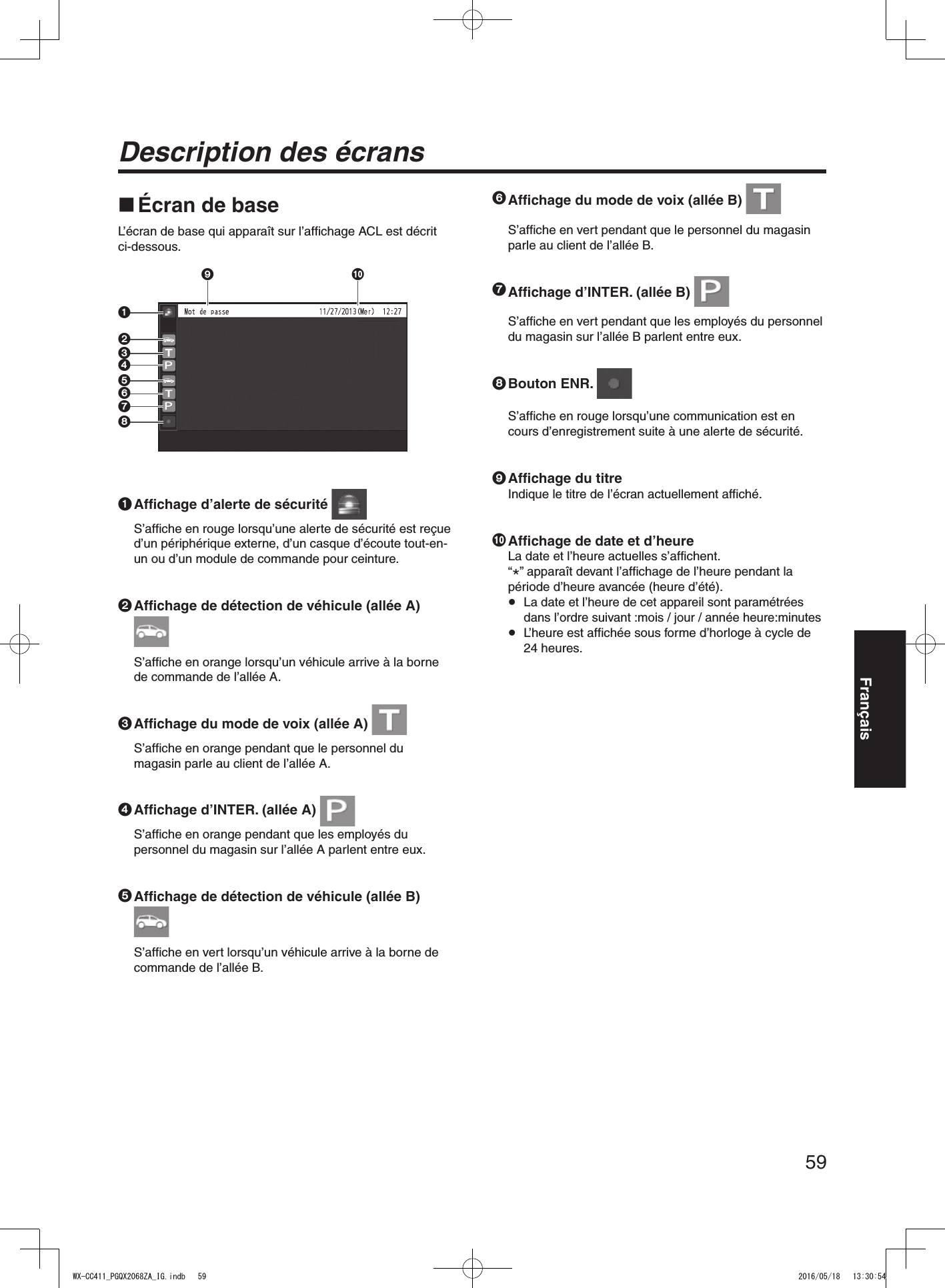
![60Description des écrans Écran Informations sur paramétragesL’écran Informations sur paramétrages apparaît lorsque l’on appuie sur (bouton Informations sur paramétrages) sur l’écran tactile. Les paramètres et états de cet appareil peuvent être vérifiés sur cet écran.1 2 3 41 Infos-paramétrages [Infos-param.]Lorsque l’on appuie sur le bouton Infos-param., l’affichage ACL permute sur l’écran de liste de paramétrages.2 Alerte de sécurité [Alerte sécurité]Lorsque l’on appuie sur le bouton Alerte sécurité, l’affichage ACL permute sur l’écran Alerte sécurité. (P.61)3 Aide-ressource [Aide-ressource]Lorsque l’on appuie sur le bouton Aide-ressource, l’affichage ACL permute sur l’écran Aide-ressource. (P.62)4 Informations sur système [Infos-système]Lorsque l’on appuie sur le bouton Infos-système, l’affichage ACL permute sur l’écran Infos-système. (P.62)Écran de liste de paramétragesL’écran de liste de paramétrages s’affiche lorsque l’on allume l’appareil ou lorsque l’on touche le bouton [Infos-param.].23 6 7 98 :4 51 1 Affichage du nom d’allée [A] ([B])Le nom de l’allée s’affiche. Les états de paramétrage de l’allée s’affichent à droite du nom de l’allée.Avec le WX-CC412A, l’allée B s’affiche aussi sous l’allée A.2 Affichage du mode d’allée [Simple/Double/Tandem]Le mode d’allée paramétré s’affiche.WX-CC411A : [Simple] s’affiche.WX-CC412A : [Double] s’affiche lorsque le paramètre d’allée tandem est NON, et [Tandem] lorsqu’il est OUI.3 Affichage du volume de nuit [Volume de nuit OUI/NON/AUTO]L’état de paramétrage du volume de nuit du haut-parleur de la borne de commande s’affiche. Le “volume de nuit” est une fonction qui sert à ajuster le niveau du volume de la sortie vocale émise par le haut-parleur de la borne de commande.Remarque4 Affichage de l’équipe express [Équipe exp OUI/NON]L’état de l’opération d’équipe express s’affiche. “Opération Équipe express” désigne un mode d’opération où, lorsque l’achalandage des véhicules dépasse la capacité des allées, le fonctionnement normal est interrompu, les détecteurs de véhicule sont fermés et les membres du personnel du magasin se rendent en personne aux véhicules des clients pour prendre les commandes.Remarque5 Affichage Bip trans. [Bip trans. OUI/NON]L’état du bip trans-allée est affiché.Il n’apparaît qu’avec le WX-CC412A. “Bip trans.” est une fonction qui sert à envoyer une tonalité pour annoncer l’arrivée des clients sur les deux allées.Remarque6 Affichage du volume du haut-parleur de la borne de commande d’allée A [Ext.]Le niveau du volume du haut-parleur de la borne de commande d’allée A s’affiche.7 Affichage du volume du haut-parleur de la cuisine d’allée A [AUX]Le niveau du volume du haut-parleur de la cuisine d’allée A s’affiche.WX-CC411_PGQX2068ZA_IG.indb 60 2016/05/18 13:30:55](https://usermanual.wiki/Panasonic-of-North-America/9TAWX-CC412A/User-Guide-3068481-Page-60.png)
![61Français8 Affichage du volume du microphone de la borne de commande d’allée A [Ext.]Le niveau du volume du microphone de la borne de commande d’allée A s’affiche.9 Affichage du volume du microphone de la cuisine d’allée A [AUX]Le niveau du volume du microphone de la cuisine d’allée A s’affiche.: Affichage du volume de la tonalité d’allée A [Bip]Le niveau du volume de la tonalité d’allée A s’affiche. Affichage du volume d’entrée de ligne d’allée A [E-ligne]Le niveau du volume de l’entrée de ligne d’allée A s’affiche. Affichage du volume de sortie de ligne d’allée A [S-ligne]Le niveau du volume de la sortie de ligne d’allée A s’affiche. Affichage OUI/NON du microphone de la borne de commande d’allée A [Mic.ex OUI/NON]Le paramètre qui détermine s’il faut émettre la voix du microphone de la borne de commande d’allée A vers le haut-parleur de la cuisine d’allée A s’affiche. Affichage OUI/NON du microphone de la cuisine d’allée A [Mic.AUX OUI/NON]Le paramètre qui détermine s’il faut émettre la voix du microphone de la cuisine d’allée A vers le haut-parleur de la cuisine d’allée A s’affiche. Affichage OUI/NON de voix d’allée A [VOIX OUI/NON]Le paramètre qui détermine s’il faut émettre la voix vers le haut-parleur de la cuisine d’allée A s’affiche. “Voix” désigne les communications entre les clients et le personnel du magasin.Remarque Affichage OUI/NON de la tonalité d’allée A [Bip OUI/NON]Le paramètre qui détermine s’il faut émettre la tonalité vers le haut-parleur de la cuisine d’allée A s’affiche. Affichage OUI/NON d’INTER. d’allée A [INTER. OUI/NON]Le paramètre d’intercommunication d’allée A s’affiche. “Intercommunication” désigne les communications entre les membres du personnel du magasin.Remarque Affichage OUI/NON de Détect./V. désactivé d’allée A [Dét/V désact. OUI/NON]L’état de Détect./V. désactivé de l’allée A s’affiche. “Détect./V. désactivé” est une fonction qui sert à paramétrer les détecteurs de véhicule virtuellement sur OUI et à maintenir le microphone et le haut-parleur de la borne de commande sur le paramètre OUI.RemarqueÉcran Alerte sécuritéL’écran Alerte sécurité apparaît lorsque l’on appuie sur le bouton [Alerte sécurité] sur l’écran Informations sur paramétrages.1 231 Cause et Temps d’initiationLa cause de l’alerte de sécurité et l’heure du déclenchement s’affichent.[Touche F] : Alertes envoyées par les membres du personnel du magasin équipés de casques d’écoute tout-en-un ou de modules de commande pour ceinture.[Alertes 1 à 4] : Alertes envoyées par les périphériques externes 1 à 4.2 Bouton Effacer [Effacer]Appuyer sur ce bouton pour forcer l’annulation de l’alerte de sécurité.3 Bouton Arrêt. [Arrêt.]Appuyer sur ce bouton pour arrêter le message d’alerte de l’alerte de sécurité.Il apparaît lorsque la “Lecture de message d’alerte” a été paramétrée pour les opérations à effectuer après le déclenchement d’une alerte de sécurité.WX-CC411_PGQX2068ZA_IG.indb 61 2016/05/18 13:30:56](https://usermanual.wiki/Panasonic-of-North-America/9TAWX-CC412A/User-Guide-3068481-Page-61.png)
![62Description des écransÉcran Aide-ressourceL’écran Aide-ressource apparaît lorsque l’on appuie sur le bouton [Aide-ressource] sur l’affichage ACL.Les coordonnées du service d’aide d’urgence s’affichent sur cet écran. Ces coordonnées peuvent être définies sur l’écran de paramétrages. Il est possible d’envoyer un courriel depuis cet écran si l’adresse de courriel a été paramétrée à l’avance au moyen du navigateur. Il n’est pas possible d’afficher le résultat de l’envoi du courriel lorsque, par exemple, l’envoi échoue parce que le serveur est en panne ou que l’adresse de courriel paramétrée est erronée. Au moment de l’installation de cet appareil, vérifier à l’avance si l’envoi des courriels fonctionne bien.RemarqueÉcran Infos-systèmeL’écran Infos-système apparaît lorsque l’on appuie sur le bouton [Infos-système] sur l’affichage ACL.L’état du réseau est indiqué sur cet écran. Écran de saisie du mot de passeLe mot de passe doit être saisi pour vérification avant que l’on puisse passer à l’écran de paramétrages.L’écran de saisie du mot de passe apparaît lorsque l’on appuie sur (bouton de paramétrage). Pour plus de détails sur la façon de saisir les caractères, se reporter à “Saisie des caractères”, p.74.Mot de passe par défaut: 12345 Par mesure de sécurité, modifier le mot de passe à intervalles réguliers.Important Écran de contrôle des camérasL’écran de contrôle des caméras apparaît sur l’affichage ACL lorsque l’on appuie sur (bouton d’affichage de caméra) sur l’écran tactile.1324567891 Écran de caméra 1L’image de la caméra en réseau 1 apparaît dans cette partie de l’écran.2 Écran de caméra 2L’image de la caméra en réseau 2 apparaît dans cette partie de l’écran.3 Écran de caméra 3L’image de la caméra en réseau 3 apparaît dans cette partie de l’écran.WX-CC411_PGQX2068ZA_IG.indb 62 2016/05/18 13:30:58](https://usermanual.wiki/Panasonic-of-North-America/9TAWX-CC412A/User-Guide-3068481-Page-62.png)
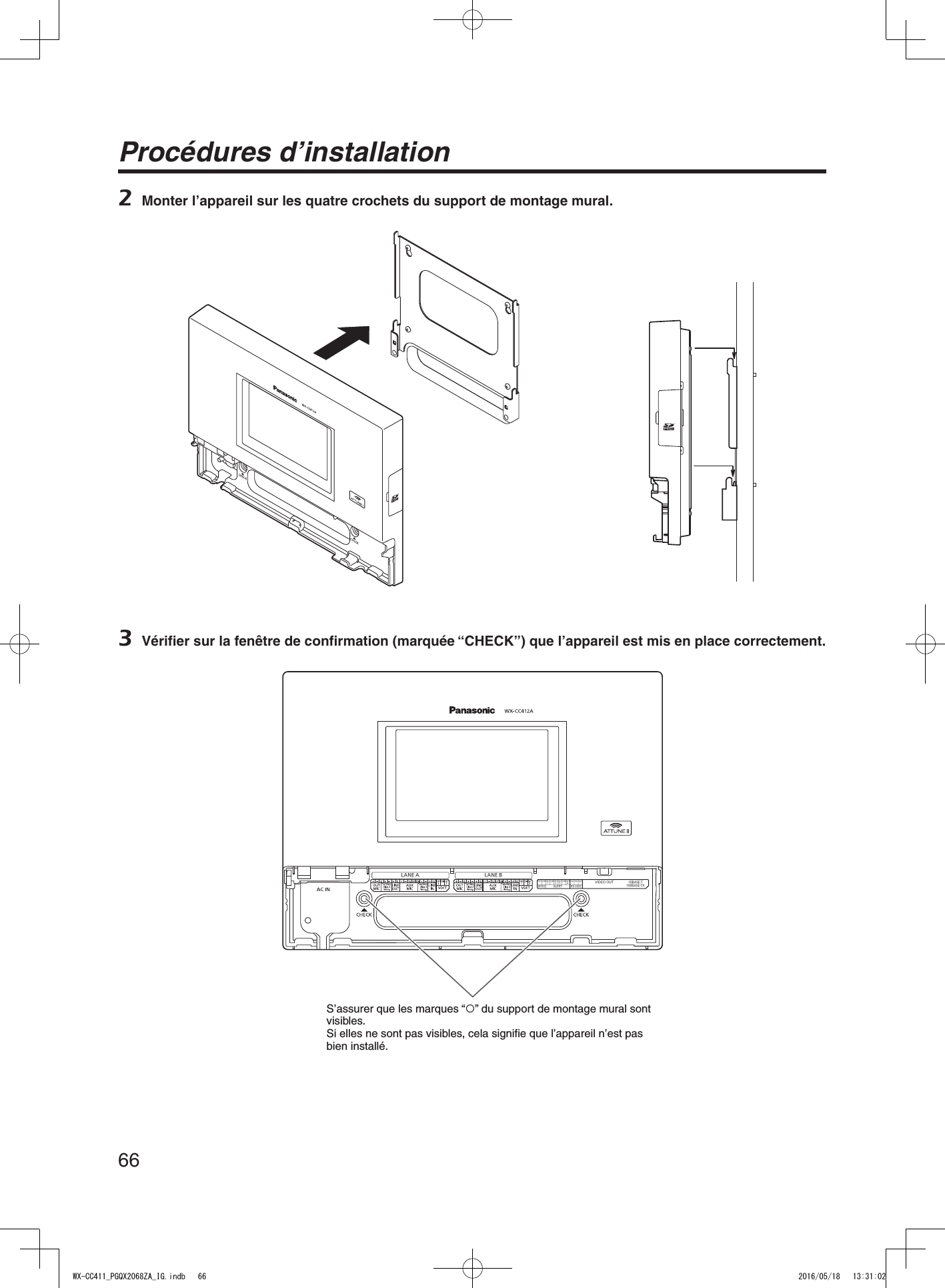
![65FrançaisProcédures d’installation Choix de l’emplacement d’installation du module centralChoisir un mur pour le montage de l’appareil, percer un trou dans le mur pour y faire passer les câbles, et choisir l’emplacement des quatre vis, tel qu’illustré ci-dessous.19013525402005 S’assurer que la surface d’installation a la résistance à l’arrachement indiquée ci-dessous.Important Installation1 Monter l’appareil à l’aide du support de montage mural en accessoire et des 4 vis (4,1 mm × 25 mm {5/32 po × 63/64 po}). [Résistance minimale à l’arrachement : 780 N {80 kgf}]Vis (à se procurer localement)(vis à bois : 4,1 mm × 25 mm {5/32 po × 63/64 po})Voie de passage des câblesWX-CC411_PGQX2068ZA_IG.indb 65 2016/05/18 13:31:01](https://usermanual.wiki/Panasonic-of-North-America/9TAWX-CC412A/User-Guide-3068481-Page-65.png)
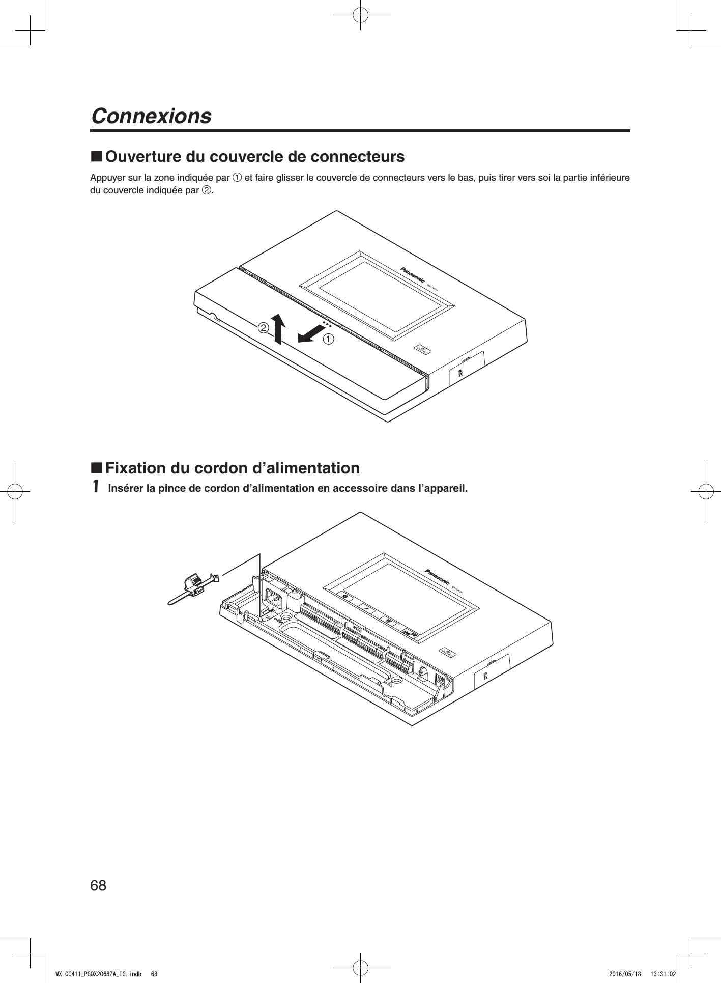
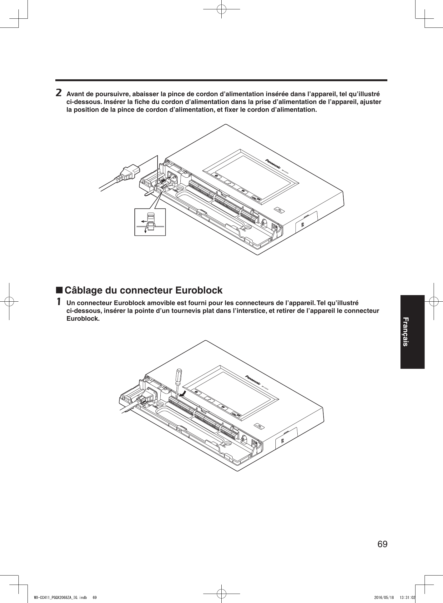
![67Français4 Utiliser la pince en accessoire pour fixer le cordon d’alimentation au mur, et fixer la pince à l’aide de la vis (4,1 mm × 25 mm {5/32 po × 63/64 po}). [Résistance minimale à l’arrachement : 780 N {80 kgf}]Vis (à se procurer localement)150 mm à 200 mm{5-15/16 po à 7-7/8 po}WX-CC411_PGQX2068ZA_IG.indb 67 2016/05/18 13:31:02](https://usermanual.wiki/Panasonic-of-North-America/9TAWX-CC412A/User-Guide-3068481-Page-67.png)
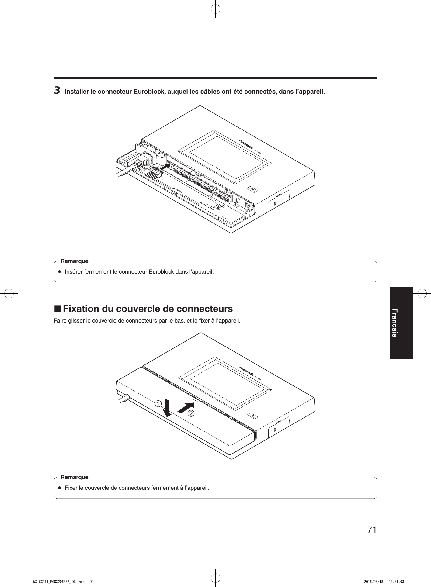
![73FrançaisCommandes sur écran Commandes de base sur écranCette section décrit les commandes de base sur écran.Pour plus de détails sur l’utilisation de l’appareil et la sélection des paramètres, se reporter au “Manuel d’utilisation <Instructions de configuration>” (fichier PDF).2131 Bouton de retourCe bouton sert à revenir à l’écran précédent.2 Boutons de sélection d’optionL’opération permute sur l’écran correspondant au bouton sur lequel on a appuyé. Sur l’écran de paramétrage, un des boutons est sélectionné (il est indiqué en orange).Suivant la situation, les boutons portent des noms différents.3 Boutons de sélection de pageCes boutons servent à sélectionner la page lorsque l’écran occupe plusieurs pages. Lorsque l’on appuie sur le bouton ▼ l’écran de la page suivante s’affiche, et lorsque l’on appuie sur le bouton ▲ l’écran de la page précédente s’affiche. Comme l’affichage ACL se raye facilement, toujours effectuer les commandes avec un doigt. Ne pas utiliser un stylo à bille ou tout autre objet à pointe dure ou tranchante, y compris les ongles, pour effectuer les commandes sur l’écran tactile. Ne pas appuyer trop fort sur l’affichage ACL. Ne pas utiliser les pellicules de protection pour affichage ACL disponibles sur le marché. (L’écran tactile risquerait de ne pas bien fonctionner.) Il se peut que la face intérieure de l’affichage ACL s’embue ou que de la condensation (des gouttelettes d’eau) prenne forme et que l’affichage ne fonctionne pas bien lorsque la température varie brusquement, par exemple après la mise en marche d’un climatiseur ou d’un appareil de chauffage. Le cas échéant, laisser l’appareil s’adapter à la température pendant une heure ou deux avant de le réutiliser.Remarque Saisie des paramètresSur un écran à options de paramétrage multiples, toucher le bouton [Régler] pour valider un paramètre.11 Bouton RéglerCe bouton sert à valider tous les paramètres qui s’affichent ensemble sur l’écran. WX-CC411_PGQX2068ZA_IG.indb 73 2016/05/18 13:31:06](https://usermanual.wiki/Panasonic-of-North-America/9TAWX-CC412A/User-Guide-3068481-Page-73.png)
![74Commandes sur écran Saisie des caractèresLorsqu’il faut saisir un mot de passe ou une adresse, utiliser les boutons du clavier pour saisir les caractères.1243561 Zone d’affichage des caractères saisisLes caractères saisis s’affichent.2 Bouton Espace arr.Appuyer sur ce bouton pour supprimer le dernier des caractères dans la zone d’affichage des caractères saisis.3 Boutons de saisie des caractèresLe caractère du bouton sur lequel on appuie est saisi.4 Bouton EspaceAppuyer sur ce bouton pour saisir une espace.5 Bouton Régler/Entrer [Entrer/Connexion]Appuyer sur ce bouton pour valider la chaîne de caractères saisie.6 Bouton de sélection du type de caractèresAppuyer sur ce bouton pour changer le type de caractères à saisir. Saisie de la date et de l’heureSaisir la date et l’heure en utilisant des boutons [+] et [–].2 311 Zone d’affichage des valeurs de paramétrageLes valeurs de paramétrage actuelles s’affichent.2 Boutons + et –Ajuster les paramètres en appuyant sur les boutons + et –.3 Bouton Régler/Entrer [Régler/Entrer]Appuyer sur ce bouton pour valider l’heure saisie. Ajustement du niveau du volumeAjuster le niveau du volume.2 1 21 Zone d’affichage du niveau du volumeLes niveaux de volume actuels s’affichent.2 Boutons + et –Ajuster les niveaux en appuyant sur les boutons + et –.Les modifications apportées au niveau du volume s’appliquent immédiatement.WX-CC411_PGQX2068ZA_IG.indb 74 2016/05/18 13:31:07](https://usermanual.wiki/Panasonic-of-North-America/9TAWX-CC412A/User-Guide-3068481-Page-74.png)
![75FrançaisProcédures d’utilisation Opérations de baseVOIX : Pour parler aux clientsCette fonction sert aux conversations bidirectionnelles entre les membres du personnel du magasin qui portent les casques d’écoute tout-en-un ou modules de commande pour ceinture et le client à la borne de commande.Pour plus de détails sur les méthodes de conversation, se reporter au Manuel d’utilisation du module de commande pour ceinture (WX-CT420) ou du casque d’écoute tout-en-un (WX-CH450).Intercommunication : Pour parler aux autres membres du personnel du magasinLes membres du personnel du magasin qui portent les casques d’écoute tout-en-un ou les modules de commande pour ceinture peuvent parler entre eux sans être entendus des clients.Pour plus de détails sur les méthodes d’intercommunication, se reporter au Manuel d’utilisation du module de commande pour ceinture (WX-CT420) ou du casque d’écoute tout-en-un (WX-CH450).Permutation d’allée de service au volant double (uniquement avec le WX-CC412A)Dans le cas d’un service au volant double, il est possible de sélectionner l’allée A ou l’allée B en mode de voix ou d’intercommunication.Pour plus de détails sur la façon d’effectuer une permutation d’allée, se reporter au Manuel d’utilisation du module de commande pour ceinture (WX-CT420) ou du casques d’écoute tout-en-un (WX-CH450). Enregistrement ID Pour pouvoir utiliser le mode de voix ou d’intercommunication au moyen d’un casque d’écoute tout-en-un ou d’un module de commande pour ceinture, il faut que son identifiant (ID) soit enregistré. Pour l’enregistrement ID, paramétrer le module central sur le mode d’enregistrement ID, et effectuer l’enregistrement sur le casque d’écoute tout-en-un ou le module de commande pour ceinture en question.La procédure d’enregistrement ID est décrite ci-dessous avec, à titre exemple, l’utilisation d’un casque d’écoute tout-en-un ou module de commande pour ceinture.1 Appuyer sur (bouton de paramétrage) sur le panneau tactile. L’écran de saisie du mot de passe apparaît.2 Saisir le mot de passe, et appuyer sur le bouton [Connexion].Mot de passe par défaut: 12345 Par mesure de sécurité, modifier le mot de passe à intervalles réguliers.Important Le menu de paramétrage s’affiche.WX-CC411_PGQX2068ZA_IG.indb 75 2016/05/18 13:31:08](https://usermanual.wiki/Panasonic-of-North-America/9TAWX-CC412A/User-Guide-3068481-Page-75.png)
![76Procédures d’utilisation3 Appuyer sur le bouton [Casques d’écoute], puis sur le bouton [Enregistrement ID]. L’écran Enregistrement ID apparaît. Les numéros des casques d’écoute tout-en-un ou de modules de commande pour ceinture enregistrés s’affichent dans la zone [Casques d’écoute enregistrés]. Une fois terminé l’enregistrement ID, l’ID du nouveau casque d’écoute tout-en-un ou du module de commande pour ceinture enregistré est ajouté. Remarque4 Appuyer sur le bouton [Lancer]. L’écran flash suivant s’affiche. Il n’est pas possible d’effectuer d’autres opérations pendant l’enregistrement ID. Pour poursuivre l’enregistrement ID, appuyer sur le bouton [OUI]. Pour arrêter l’enregistrement ID, appuyer sur le bouton [NON]. Le mode d’enregistrement ID s’active lorsque l’on appuie sur le bouton [OUI].Le numéro du casque d’écoute tout-en-un ou du module de commande pour ceinture enregistré s’affiche. 5 Appuyer sur le bouton [POWER] tout en maintenant enfoncés les boutons [T1] et [T2] sur le casque d’écoute tout-en-un ou le module de commande pour ceinture. Le casque d’écoute tout-en-un ou le module de commande pour ceinture démarre en mode d’enregistrement ID. Le message vocal “Mode d’enregistrement” sera émis par l’écouteur, et le témoin d’alimentation clignotera en orange. En mode d’enregistrement ID, les boutons et témoins n’ont pas les mêmes fonctions que lors du démarrage normal.6 Appuyer sur le bouton [T1] sur le casque d’écoute tout-en-un ou le module de commande pour ceinture. Le casque d’écoute tout-en-un ou le module de commande pour ceinture cherche un module central en mode d’enregistrement ID. Le message vocal “Mise en circuit du module central A” sera émis par l’écouteur, et le témoin d’allée clignotera en orange. Dans le cas du WX-CC412A, après l’enregistrement d’allée A le message vocal “Mise en circuit du module central B” sera émis, et le témoin d’allée clignotera en vert. Si l’enregistrement ID réussit, le message vocal “L’enregistrement est complété” sera émis par l’écouteur, puis le message vocal indiquant le numéro du casque d’écoute tout-en-un ou du module de commande pour ceinture enregistré sera émis. Le témoin d’alimentation et le témoin d’allée cessent alors de clignoter et restent allumés.Après avoir enregistré tous les ID de casque d’écoute, appuyer sur le bouton [Arrêter] sur l’écran Enregistrement ID.Le module central quitte le mode d’enregistrement ID. Le témoin d’alimentation du casque d’écoute tout-en-un ou du module de commande pour ceinture passe de l’orange au vert.WX-CC411A_PGQX2068ZA_IG_fr.indd 76 2016/05/20 14:12:12](https://usermanual.wiki/Panasonic-of-North-America/9TAWX-CC412A/User-Guide-3068481-Page-76.png)
![77Français Lorsque l’on enregistre l’ID de plusieurs casques d’écoute tout-en-un ou modules de commande pour ceinture, enregistrer l’ID sur un appareil à la fois. Si l’on essaie d’enregistrer l’ID de plusieurs appareils à la fois, les ID risquent de ne pas être enregistrés correctement. Pendant l’enregistrement ID, ne pas éteindre les casques d’écoute tout-en-un ou les modules de commande pour ceinture, et ne pas retirer leurs batteries. Autrement les ID risquent de ne pas être enregistrés correctement. Si l’enregistrement ne se déroule pas bien, appuyer sur le bouton [Arrêter] sur le module central, quitter le mode d’enregistrement ID, puis réessayer. Si l’enregistrement ID échoue, le casque d’écoute tout-en-un ou le module de commande pour ceinture en question émet des sons d’avertissement (BII-II-IIP), puis le message vocal “L’opération a échoué” est émis. Si un enregistrement ID échoue, l’ID du casque d’écoute tout-en-un ou du module de commande pour ceinture ne sera pas enregistré dans le module central, et le témoin d’alimentation du casque d’écoute tout-en-un ou du module de commande pour ceinture clignotera en rouge. Jusqu’à 32 ID de casque d’écoute tout-en-un ou module de commande pour ceinture peuvent être enregistrés sur un module central. Si l’on essaie d’enregistrer plus de 32 ID d’appareil, les ID des casques d’écoute restés inutilisés le plus longtemps seront automatiquement supprimés et remplacés par ceux des nouveaux appareils. Il n’est pas possible d’enregistrer l’ID d’un répéteur sans fil pendant que le mode d’enregistrement ID des casques d’écoute tout-en-un ou modules de commande pour ceinture est activé.ImportantWX-CC411_PGQX2068ZA_IG.indb 77 2016/05/18 13:31:10](https://usermanual.wiki/Panasonic-of-North-America/9TAWX-CC412A/User-Guide-3068481-Page-77.png)
![78Procédures d’utilisation Fonctions pratiques (Autres fonctions)Verrouillage automatique pour parler aux clientsCette fonction permet au casque d’écoute tout-en-un ou au module de commande pour ceinture d’un membre prédéfini du personnel du magasin de passer automatiquement en mode de voix lorsqu’un client approche de la borne de commande. (Mode de verrouillage pour parler aux clients)Pour plus de détails sur la façon de paramétrer le mode de verrouillage automatique pour parler aux clients, se reporter au Manuel d’utilisation du module de commande pour ceinture (WX-CT420) ou du casque d’écoute tout-en-un (WX-CH450).Mode de gérantUn des casques d’écoute tout-en-un ou modules de commande pour ceinture d’une allée peut être paramétré sur le mode de gérant.Le casque d’écoute tout-en-un ou le module de commande pour ceinture en mode de gérant a une priorité plus élevée, et il peut monopoliser un des quatre canaux de communication.Cela signifie que le gérant peut utiliser le mode de voix ou d’intercommunication en tout temps.Pour plus de détails sur la façon de paramétrer le mode de gérant, se reporter au Manuel d’utilisation du module de commande pour ceinture (WX-CT420) ou du casque d’écoute tout-en-un (WX-CH450).Équipe express“Opération Équipe express” désigne un mode d’opération où, lorsque l’achalandage des véhicules dépasse la capacité des allées, le fonctionnement normal est interrompu, les détecteurs de véhicule sont fermés et les membres du personnel du magasin se rendent en personne aux véhicules des clients pour prendre les commandes.1 Appuyer sur (bouton Opération express) sur le panneau tactile, puis sur le bouton [Communs].2 Appuyer sur le bouton [OUI] d’[Équipe express] pour activer l’opération Équipe express. Le message vocal “Le mode ÉQUIPE EXPRESS est activé” est émis par les écouteurs de tous les casques d’écoute tout-en-un ou modules de commande pour ceinture. En mode Équipe express, le message “Le mode ÉQUIPE EXPRESS est activé” sera émis toutes les 5 minutes par les écouteurs des casques d’écoute tout-en-un ou modules de commande pour ceinture.Remarque3 Lorsque l’on appuie sur le bouton [P] du casque d’écoute tout-en-un ou du module de commande pour ceinture, la conversation devient possible en mode de verrouillage d’intercommunication. Même si le bouton [P] est paramétré sur “Appuyer pour intercommunication”, il fonctionnera quand même en verrouillage d’intercommunication. Pour plus de détails sur les méthodes d’intercommunication, se reporter au Manuel d’utilisation du module de commande pour ceinture (WX-CT420) ou du casque d’écoute tout-en-un (WX-CH450).WX-CC411_PGQX2068ZA_IG.indb 78 2016/05/18 13:31:10](https://usermanual.wiki/Panasonic-of-North-America/9TAWX-CC412A/User-Guide-3068481-Page-78.png)
![79Français4 Pour annuler l’opération Équipe express, appuyer sur le bouton [NON] d’[Équipe express] sur l’écran de l’étape 2. Le message vocal “Le mode ÉQUIPE EXPRESS est désactivé” est émis par les écouteurs de tous les casques d’écoute tout-en-un ou modules de commande pour ceinture, et le fonctionnement normal est rétabli. En mode Équipe express, il n’est pas possible de parler aux clients des autres bornes de commande. Si l’on essaie de parler depuis un casque d’écoute tout-en-un ou un module de commande pour ceinture, le message vocal “Cette opération n’est pas autorisée” est émis par l’écouteur.RemarqueBip trans-allée (uniquement avec le WX-CC412A)“Bip trans-allée” est une fonction qui permet d’émettre une tonalité par les casques d’écoute tout-en-un ou modules de commande pour ceinture lorsqu’un client approche de la borne de commande de l’autre allée.1 Appuyer sur (bouton Opération express) sur le panneau tactile, puis sur le bouton [Communs].2 Appuyer sur le bouton [OUI] de [Bip trans-allée] pour activer le fonctionnement du Bip trans-allée. Pour annuler Bip trans-allée, appuyer sur le bouton [NON].NON : Si l’allée A a été sélectionnée, la tonalité A sera émise lorsqu’un véhicule est détecté sur l’allée A.La tonalité B ne sera toutefois pas émise même si un véhicule a été détecté sur l’allée B.OUI :Si l’allée A a été sélectionnée, la tonalité A sera émise lorsqu’un véhicule est détecté sur l’allée A.De plus, la tonalité B est émise à un niveau de volume bas même lorsqu’un véhicule a été détecté sur l’allée B.Si des véhicules ont été détectés sur les deux allées, les tonalités A et B seront émises alternativement à un niveau de volume bas.Bip trans-alléeDétecteur de véhiculeCasque d’écoute tout-en-un ou module de commande pour ceintureL’allée A est activé L’allée B est activé A BNON¡–Bip A––¡–Bip B¡ ¡Bip A Bip BOUI¡–Bip ABip à bas niveau A–¡Bip à bas niveau BBip B¡ ¡Bip A +Bip à bas niveau B Bip B +Bip à bas niveau AWX-CC411_PGQX2068ZA_IG.indb 79 2016/05/18 13:31:11](https://usermanual.wiki/Panasonic-of-North-America/9TAWX-CC412A/User-Guide-3068481-Page-79.png)
![80Procédures d’utilisationDétect./V. désactivé“Détect./V. désactivé” est une fonction qui sert à paramétrer les détecteurs de véhicule virtuellement sur OUI et à maintenir le microphone et le haut-parleur de la borne de commande sur le paramètre OUI.1 Appuyer sur (bouton Opération express) sur le panneau tactile, puis sur le bouton [Allée A/B]*.* Bouton [Allée B] n’apparaît qu’avec le WX-CC412A.2 Appuyer sur le bouton [OUI] de [Détect./V. désactivé] pour activer cette fonction. Pour annuler Détect./V. désactivé, appuyer sur le bouton [NON].NON :Lorsque le détecteur de véhicule détecte un véhicule à la borne de commande, une tonalité est émise par l’écouteur.Lorsque l’on appuie sur le bouton de mode de voix d’un casque d’écoute tout-en-un ou d’un module de commande pour ceinture, le haut-parleur et le microphone de la borne de commande s’activent.Lorsque le véhicule quitte l’allée, la détection de véhicule se désactive. Il est alors possible d’établir le paramètre NON et le mode de verrouillage automatique pour parler aux clients.OUI :Lorsque [Détect./V. désactivé] est paramétré sur OUI, cela active en permanence le microphone de la borne de commande, et la conversation est possible même si le détecteur de véhicule n’est pas sur OUI. (Il est possible de forcer l’émission de la voix captée par le microphone de la borne de commande.) Lorsque le mode Équipe express est activé, le paramètre de Détect./V. désactivé permute automatiquement sur NON. En mode Équipe express, il n’est pas possible de modifier le paramètre de Détect./V. désactivé.RemarqueAnnulation du mode de voix ou d’intercommunicationCela force l’annulation de l’état de voix (ou d’intercommunication) d’un casque d’écoute tout-en-un ou d’un module de commande pour ceinture.1 Appuyer sur (bouton Opération express) sur le panneau tactile, puis sur le bouton [Allée A/B]*.* Bouton [Allée B] n’apparaît qu’avec le WX-CC412A.2 Appuyer sur le bouton [Exécuter] pour [Libération VOIX/INTERCOM.]. Cela force la fin de la communication. Cela n’annule pas l’état de voix (ou d’intercommunication) du casque d’écoute tout-en-un ou du module de commande pour ceinture en mode de gérant.RemarqueWX-CC411_PGQX2068ZA_IG.indb 80 2016/05/18 13:31:12](https://usermanual.wiki/Panasonic-of-North-America/9TAWX-CC412A/User-Guide-3068481-Page-80.png)