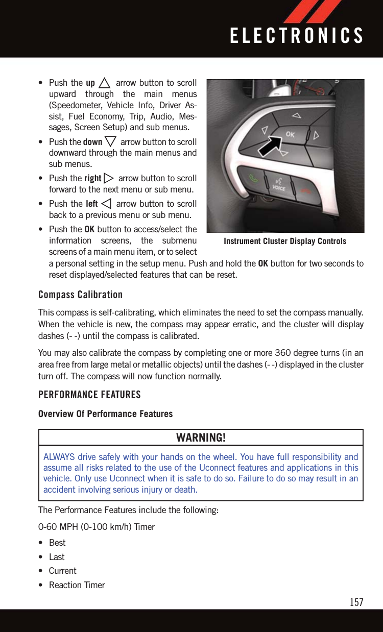
Panasonic of North America CA-170-CTPLHS CA-170-CTPL-HS radio with BT, Navigation and Integrated Display User Manual Can be modified by macros
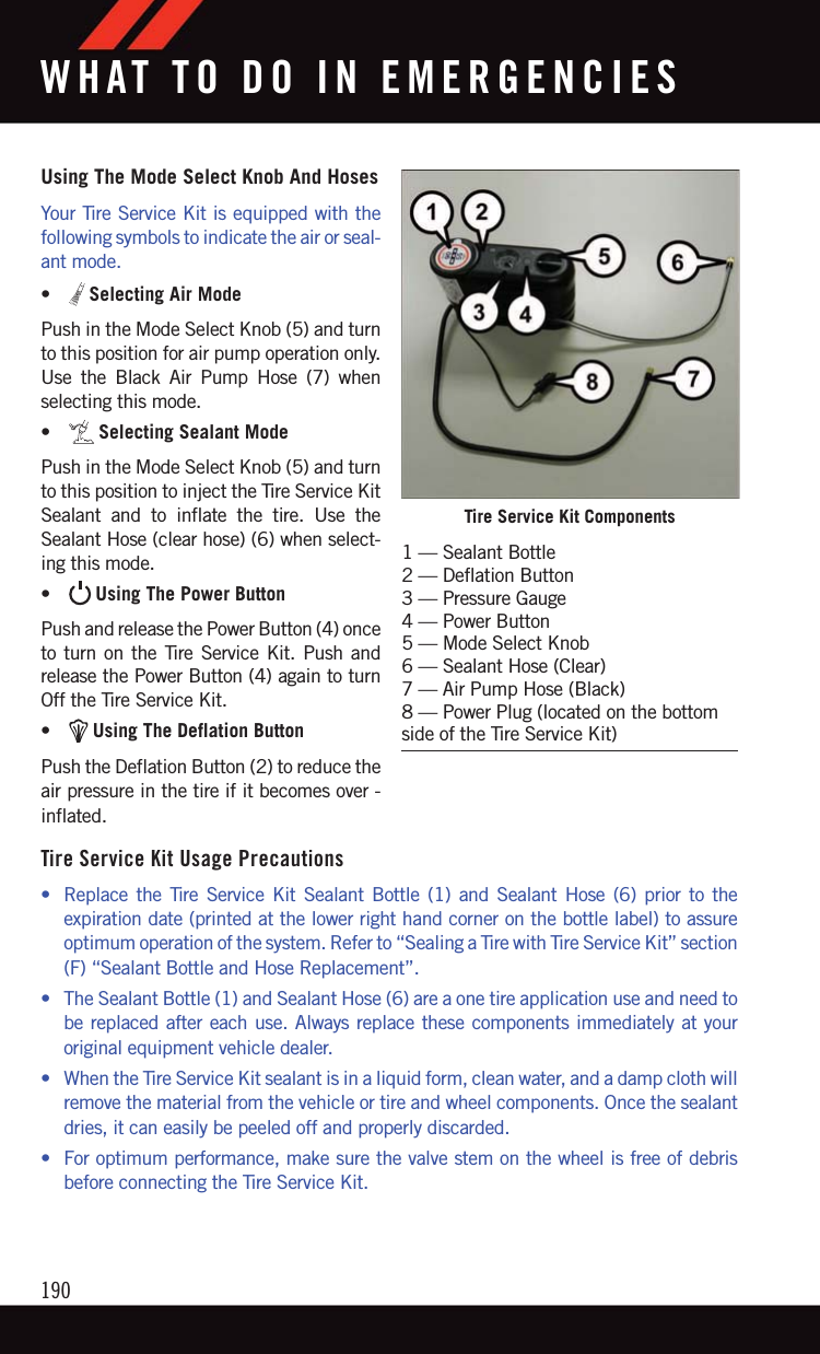
Panasonic Corporation of North America CA-170-CTPL-HS radio with BT, Navigation and Integrated Display Can be modified by macros
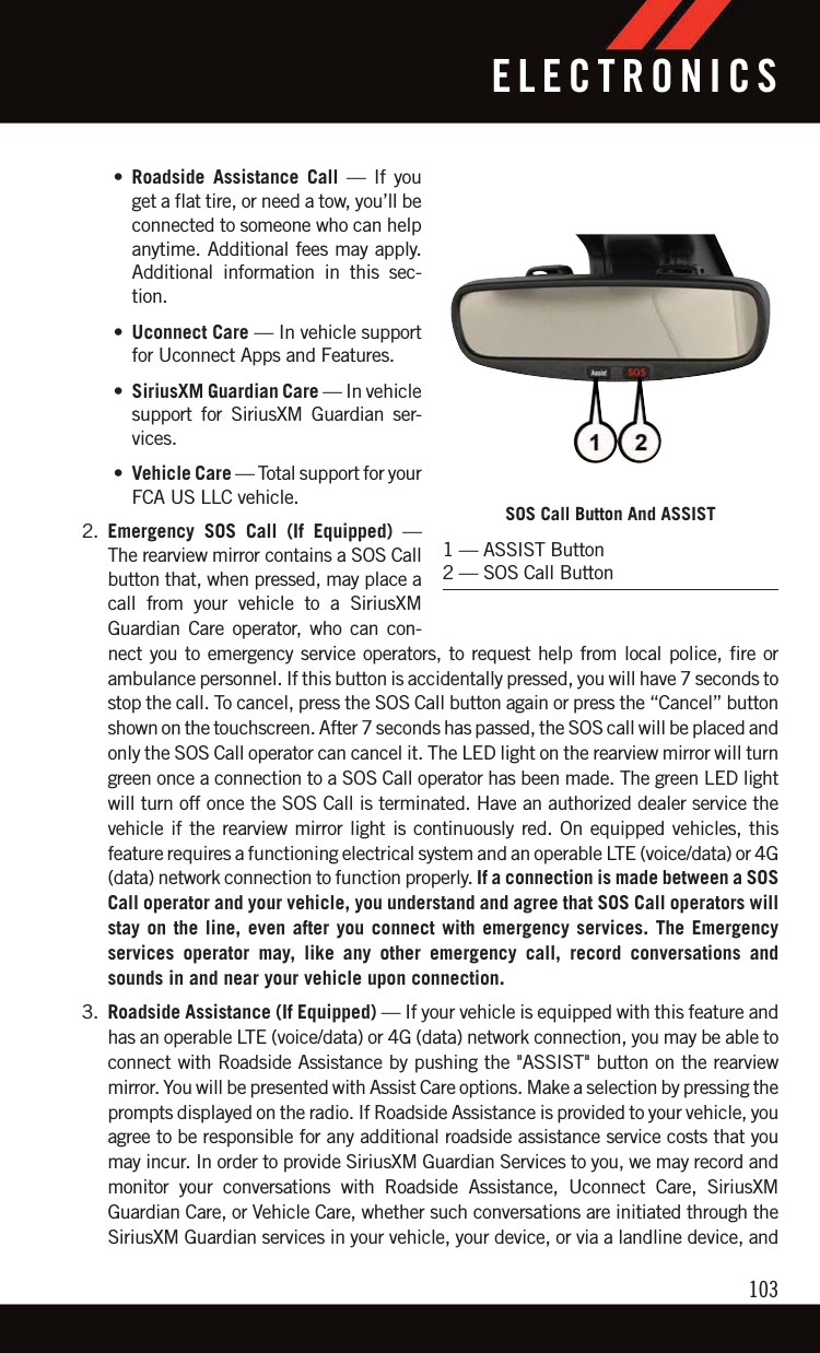
Users manual

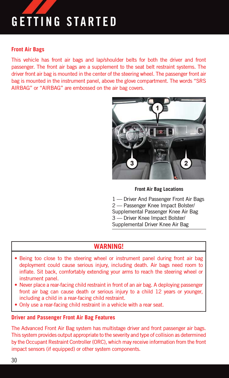
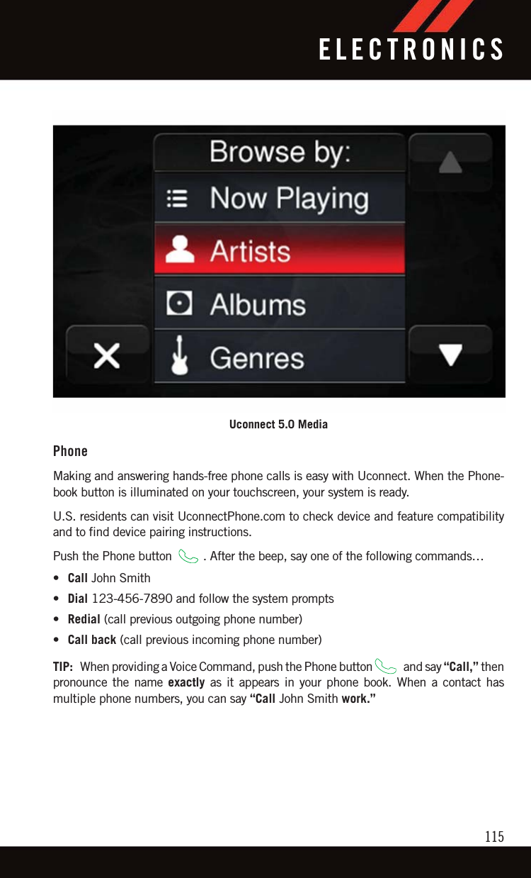
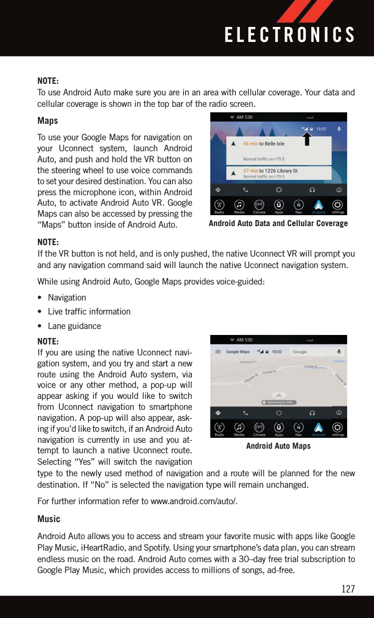
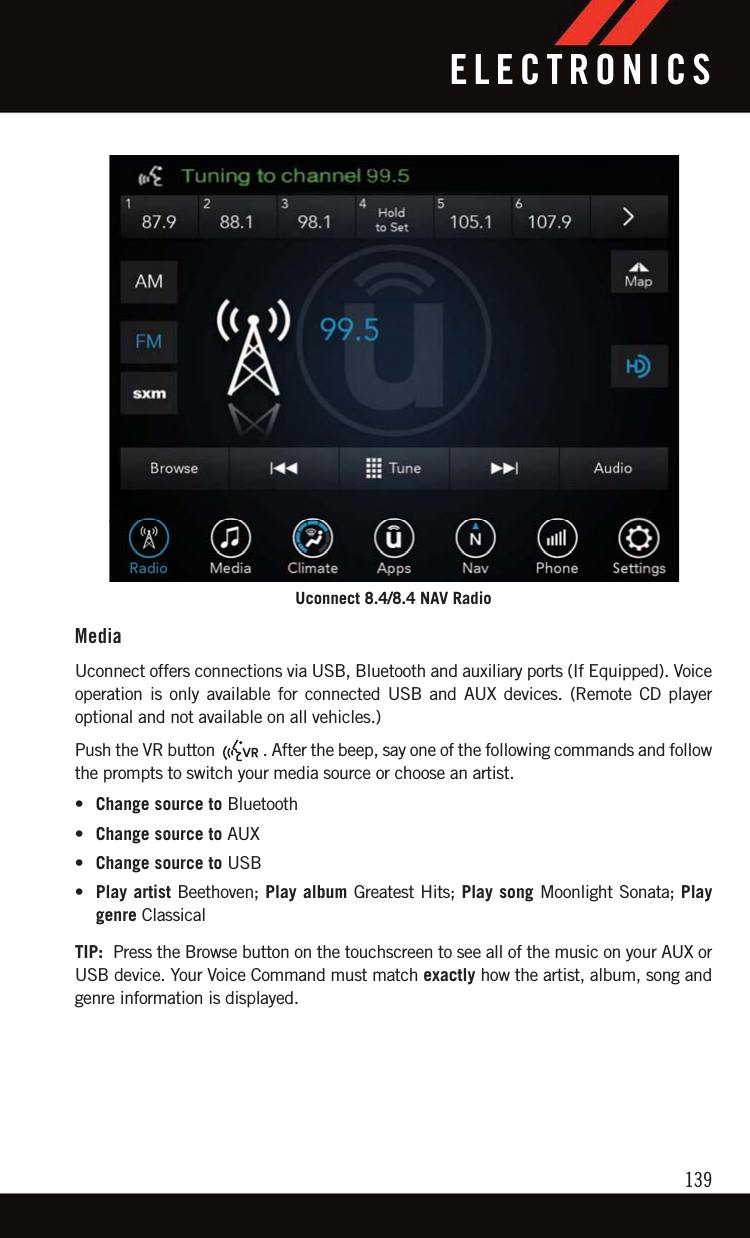
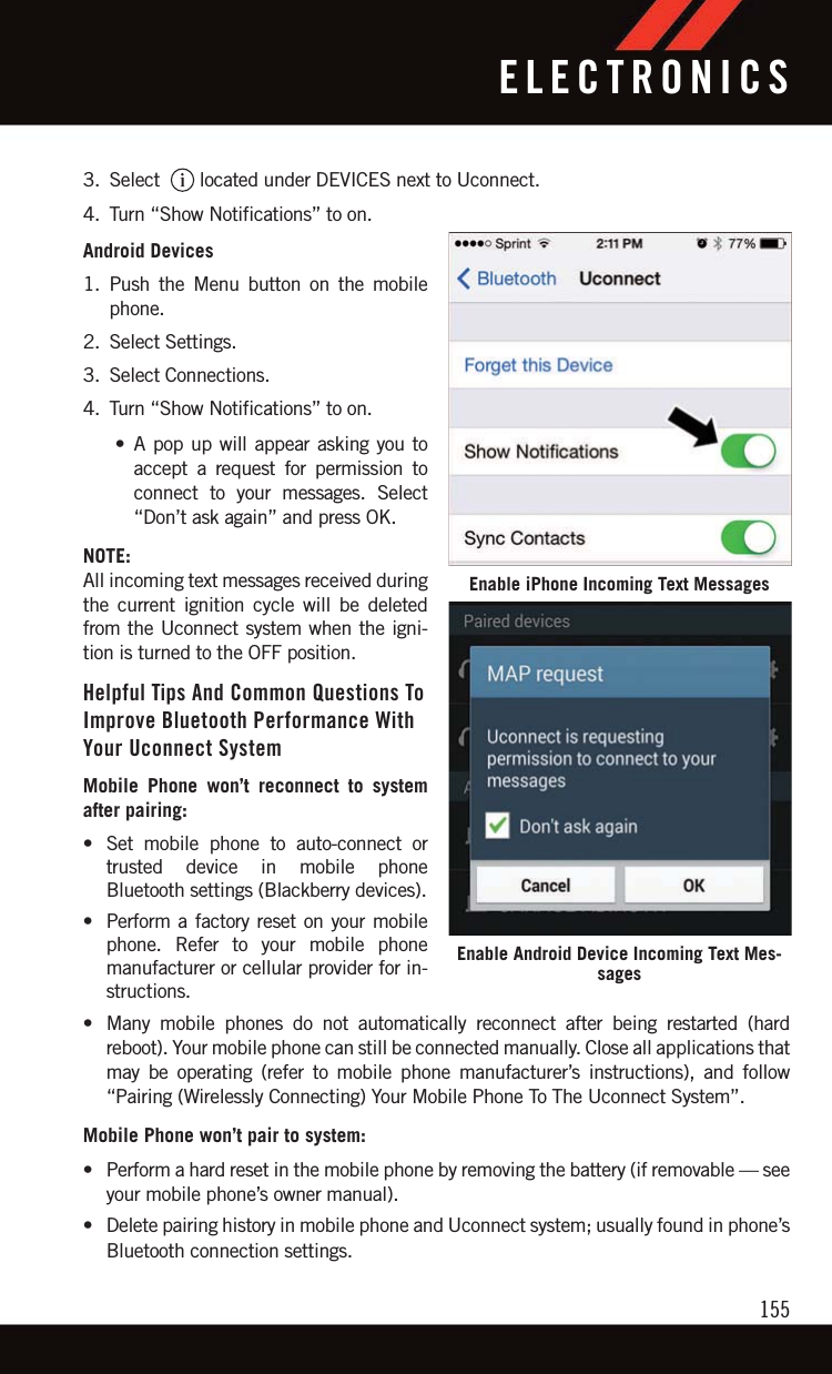
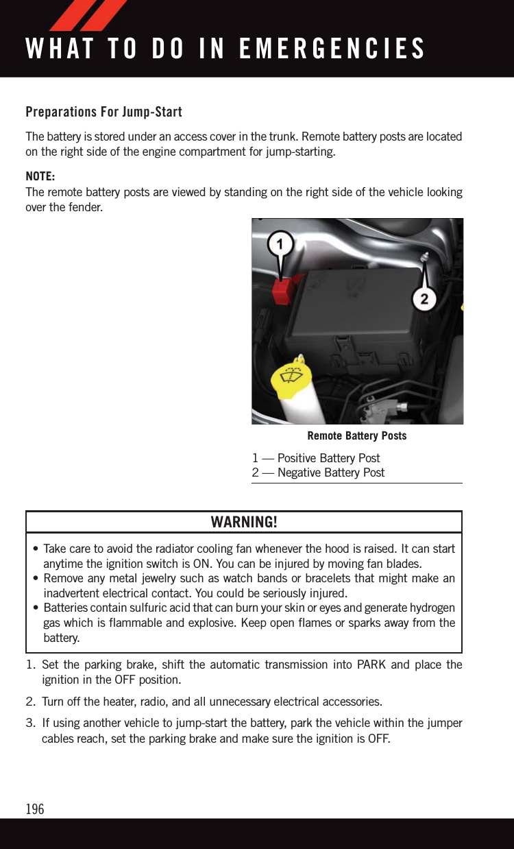
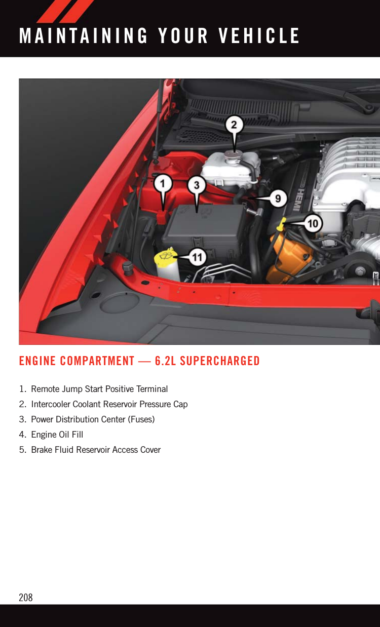
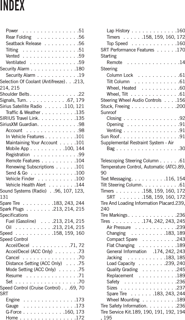
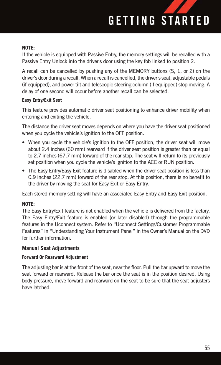
![Programming The Memory FeatureNOTE:Saving a new memory profile will erase anexisting profile from memory.To create a new memory profile, perform thefollowing:1. Place the vehicle’s ignition to the ON/RUN position.2. Adjust all memory profile settings todesired preferences (i.e., seat, side mir-ror, power tilt and telescopic steeringcolumn [if equipped], and radio stationpresets).3. Push and release the SET (S) button onthe memory switch.4. Within five seconds, push and release the MEMORY button 1 or 2. The instrumentcluster display will show which memory position has been set.NOTE:• Memory profiles can be set without the vehicle in PARK, but the vehicle must be inPARK to recall a memory profile.• To set a memory profile to your key fob, refer to “Linking And Unlinking The RemoteKeyless Entry Key Fob To Memory” in this section.Linking And Unlinking The Remote Keyless Entry Key Fob To MemoryYour key fobs can be programmed to recall one of two pre-programmed memory profilesby pushing the unlock button on the key fob.NOTE:Before programming your key fobs you must select the “Memory To FOB” or “PersonalSettings Linked To Fob” feature through the Uconnect system screen. Refer to “UconnectSettings” in “Understanding Your Instrument Panel” for further information.To program your key fobs, perform the following:1. Place the vehicle’s ignition to the OFF position.2. Select desired memory profile (1) or (2). The system will recall any stored settings forthis profile. Wait for the system to complete the memory recall before continuing toStep 3.Memory Seat SwitchesGETTING STARTED53](https://usermanual.wiki/Panasonic-of-North-America/CA-170-CTPLHS/User-Guide-3046400-Page-53.png)
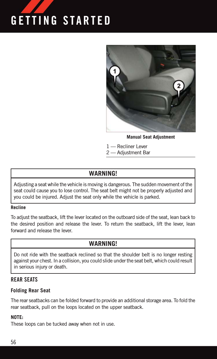

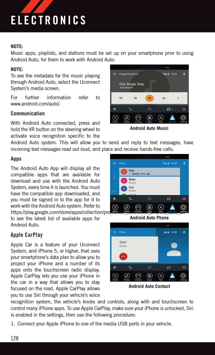
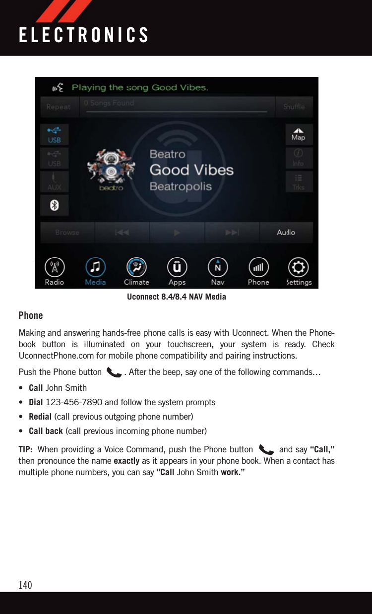
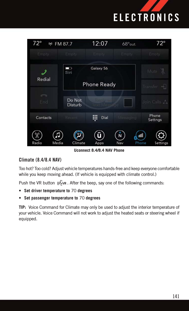
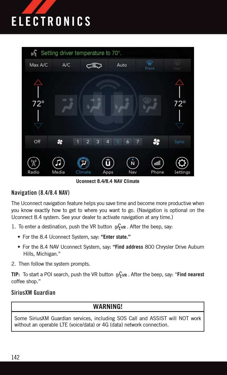
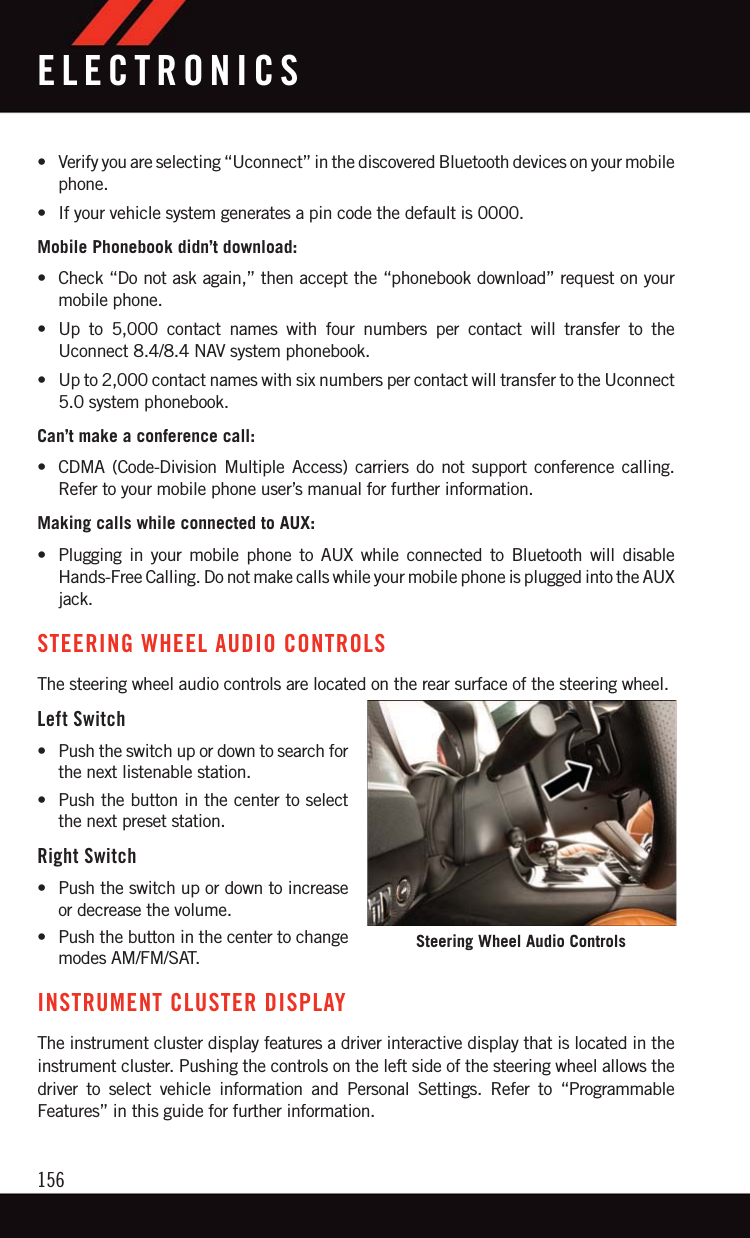
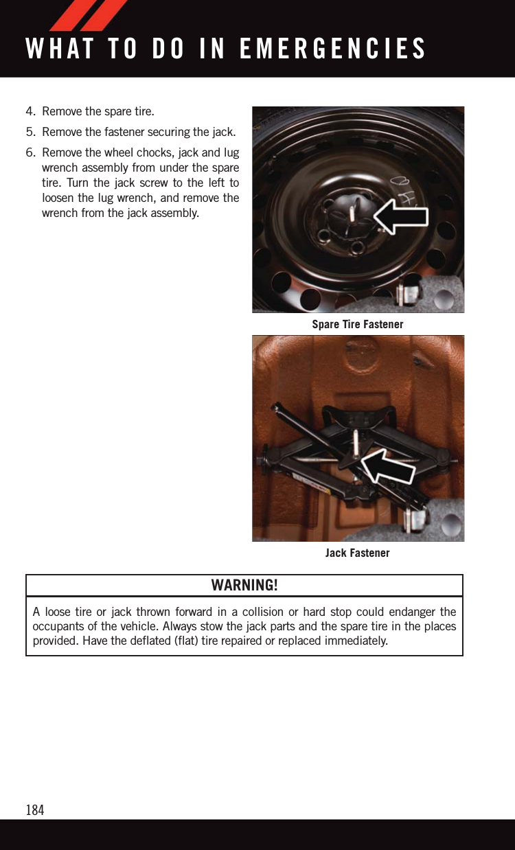
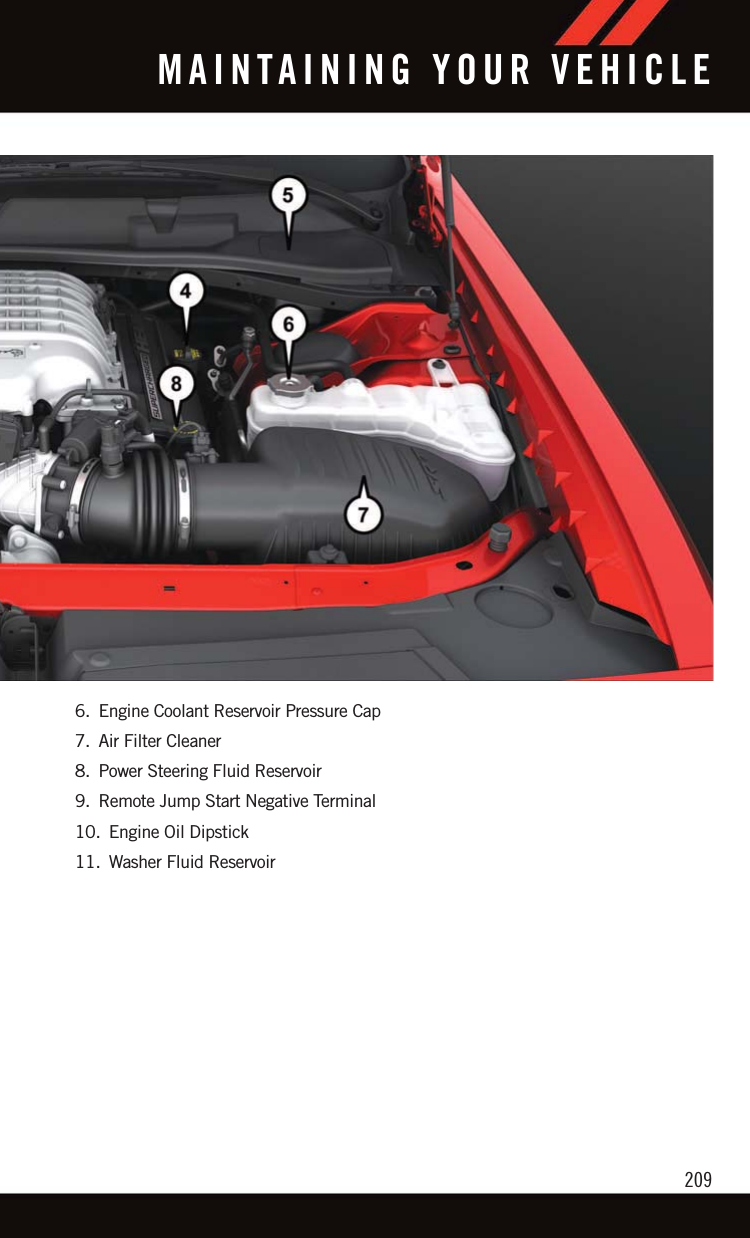
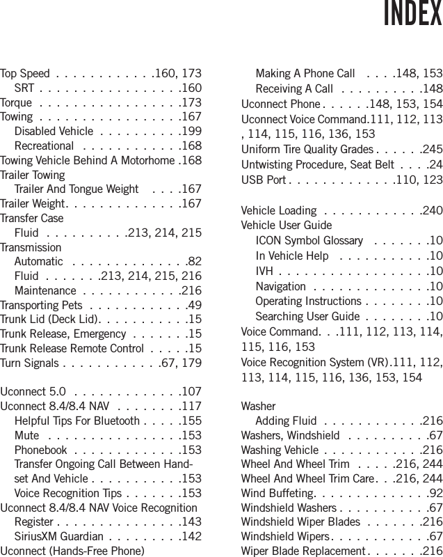
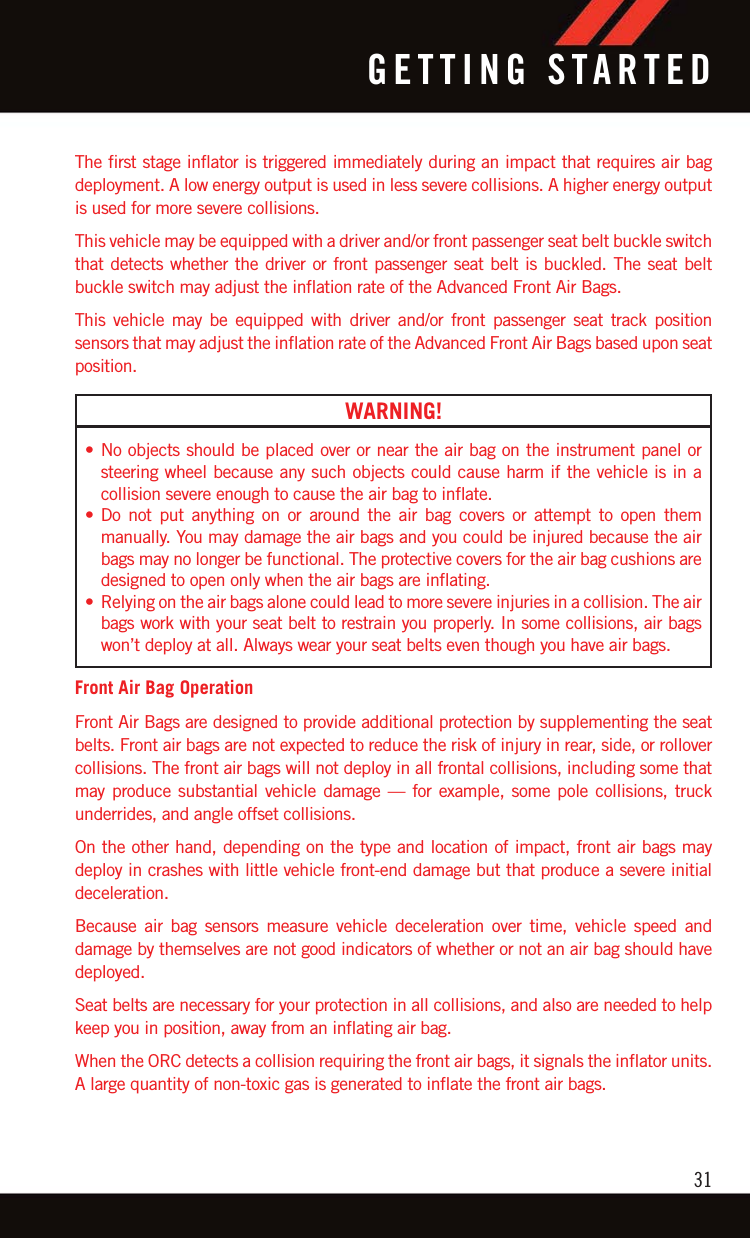
![NOTE:If the gear selector cannot be moved to the PARK, REVERSE, or NEUTRAL position (whenpushed forward) it is probably in the MANUAL (AutoStick, +/-) position (beside the DRIVEposition). In MANUAL (AutoStick) mode, the transmission gear is displayed in theinstrument cluster (as M1, M2, M3, etc.). Move the gear selector to the right (into theDRIVE [D] position) for access to PARK, REVERSE, and NEUTRAL.Refer to Automatic Transmission in the Owner’s Manual on your DVD for furtherinformation.AUTOSTICK/STEERING WHEEL MOUNTED PADDLE SHIFTERSAutoStick is a driver-interactive transmission feature that offers manual gear shifting toprovide you with more control of the vehicle. AutoStick allows you to maximize enginebraking, and improve overall vehicle performance.This system can also provide you with more control during passing, city driving, coldslippery conditions, mountain driving, trailer towing, and many other situations.OperationWhen the gear selector is in the DRIVE (D) position, the transmission will operateautomatically, shifting between the eight available gears. To activate AutoStick, move thegear selector into the MANUAL (M) position (beside the DRIVE position). The currenttransmission gear will be displayed in the instrument cluster, along with a highlighted "M"(Manual) indication. When the gear selector is in the MANUAL (M) position, tap the gearselector forward (-) (or tap the (-) shift paddle on the steering wheel, if equipped) todownshift the transmission to the next lower gear, or tap the lever rearward (+) (or tap the(+) shift paddle, if equipped) to command an upshift.NOTE:• Tapping one of the steering wheel-mounted shift paddles (+/-), if equipped,while the gear selector is in DRIVE, willactivate a temporary AutoStick mode.Tapping (-) to enter AutoStick mode willdownshift the transmission to the nextlower gear, while tapping (+) to enterAutoStick mode will retain the currentgear. The current gear will be displayedin the instrument cluster, but the "M" willnot be highlighted. The transmission willrevert back to normal operation (if thegear selector remains in DRIVE) after a period of time, depending on accelerator pedalactivity.• In some models, the shift paddles may be disabled (or re-enabled, as desired) using theUconnect Personal Settings.Shifter Paddles1 — (–) ShiftPaddle2 — (+) ShiftPaddleOPERATING YOUR VEHICLE84](https://usermanual.wiki/Panasonic-of-North-America/CA-170-CTPLHS/User-Guide-3046400-Page-84.png)
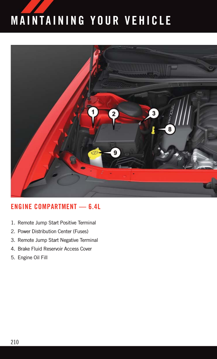
![In AutoStick mode, the transmission will shift up or down when (+/-) is manually selectedby the driver (using the gear selector, or the shift paddles [if equipped]), unless an enginelugging or overspeed condition would result. It will remain in the selected gear untilanother upshift or downshift is chosen, except as described below.• In temporary AutoStick mode (gear selector in DRIVE), the transmission will automati-cally shift up when maximum engine speed is reached. If the accelerator is fullydepressed, the transmission will downshift when possible (based on current vehiclespeed and gear, except 6.4L models). Lack of accelerator pedal activity will cause thetransmission to revert to automatic operation.• If normal AutoStick mode is engaged (gear selector in MANUAL position), manual gearselection will be maintained until the gear selector is returned to DRIVE, or asdescribed below. The transmission will not upshift automatically at redline in thismode, nor will downshifts be obtained if the accelerator pedal is pressed to the floor.• The transmission will automatically downshift as the vehicle slows (to prevent enginelugging) and will display the current gear.• The transmission will automatically downshift to first gear when coming to a stop. Aftera stop, the driver should manually upshift (+) the transmission as the vehicle isaccelerated.• You can start out, from a stop, in first or second gear. Tapping (+) (at a stop) will allowstarting in second gear. Starting out in second gear can be helpful in snowy or icyconditions.• If a requested downshift would cause the engine to over-speed, that shift will not occur.• The system will ignore attempts to upshift at too low of a vehicle speed.• Holding the (-) paddle depressed (if equipped), or holding the gear selector in the (-)position, will downshift the transmission to the lowest gear possible at the currentspeed.• Transmission shifting will be more noticeable when AutoStick is enabled.• The system may revert to automatic shift mode if a fault or overheat condition isdetected.To disengage AutoStick mode, return the gear selector to the DRIVE position, or press andhold the (+) shift paddle (if equipped, and the gear selector is already in DRIVE) until “D”is once again indicated in the instrument cluster. You can shift in or out of the AutoStickmode at any time without taking your foot off the accelerator pedal.WARNING!Do not downshift for additional engine braking on a slippery surface. The drive wheelscould lose their grip and the vehicle could skid, causing a collision or personal injury.OPERATING YOUR VEHICLE85](https://usermanual.wiki/Panasonic-of-North-America/CA-170-CTPLHS/User-Guide-3046400-Page-85.png)