Panasonic of North America CP8564 Active RF Security Tag User Manual
Omni-ID USA Inc. Active RF Security Tag
User Manual


TABLE OF CONTENTS
1 Protocol ................................................................................................................................................................. 4
1.1 Read/Write Parameters ............................................................................................................................... 4
1.2 Read Only Parameters.................................................................................................................................. 4
1.3 433MHz Radio .............................................................................................................................................. 4
1.3.1 Announce Timing ..................................................................................................................................... 4
1.3.2 Announce Reasons ................................................................................................................................... 5
1.4 Requested Operations ................................................................................................................................. 5
1.5 Commanded Operations .............................................................................................................................. 7
2 FW Upgrade ........................................................................................................................................................... 9
2.1 .............................................................................................................................................................................. 9
3 Triggers ................................................................................................................................................................ 10
3.1 Magnetic Switch ......................................................................................................................................... 10
3.2 RFID ............................................................................................................................................................ 10
3.2.1 NXP IC (Gen 1 HW) ................................................................................................................................. 10
3.2.2 Monza (Gen 1.5 HW) ............................................................................................................................. 12
4 Event Macros ....................................................................................................................................................... 15
4.1 Events ......................................................................................................................................................... 15
4.2 Operations.................................................................................................................................................. 15
4.3 Memory Layout .......................................................................................................................................... 16
5 Templates ............................................................................................................................................................ 17
5.1 Template Fields .......................................................................................................................................... 17
5.2 Template Data ............................................................................................................................................ 17
5.3 Memory Layout .......................................................................................................................................... 18
5.4 Commands ................................................................................................................................................. 18
5.5 Limitations .................................................................................................................................................. 19
6 Text Rendering ..................................................................................................................................................... 20

6.1 Character Set .............................................................................................................................................. 20
6.2 Character Font Size .................................................................................................................................... 21
7 External Flash ....................................................................................................................................................... 22
7.1 Memory Map ............................................................................................................................................. 22
7.2 Space Between Images .............................................................................................................................. 22
7.2.1 Image Dirty Byte .................................................................................................................................... 23
7.2.2 Template Dirty Byte ............................................................................................................................... 23
8 Event Log ............................................................................................................................................................. 24
8.1 Overview .................................................................................................................................................... 24
8.2 Cheat Sheet ................................................................................................................................................ 25
8.3 Log Header ................................................................................................................................................. 27
8.4 LOG_CHANGE_ ........................................................................................................................................... 27
9 Internal Flash ....................................................................................................................................................... 28
9.1 Address Map .............................................................................................................................................. 28
9.2 Calibration Data “.infoD” ........................................................................................................................... 31
9.3 HW Configuration....................................................................................................................................... 31
10 Testing ............................................................................................................... Error! Bookmark not defined.
11 Power Measurements .................................................................................................................................... 32
11.1 Revision 01.03.00.00 .................................................................................................................................. 32
1 PROTOCOL
1.1 Read/Write Parameters
Parameter
Units
Min
Default
Max
Awake Dwell
Seconds
1
2
4
Sleep Dwell
Seconds
4
64800
2^32
Retry Dwell
Seconds
1
5
5
Retry Count
Attempts
0
5
5
ACK Listen Time
mS
-
200
-
RF Channel
-
0x01
-
TX Power
10
10
1.2 Read Only Parameters
1.3 433MHz Radio
1.3.1 Announce Timing
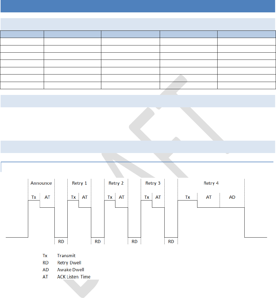
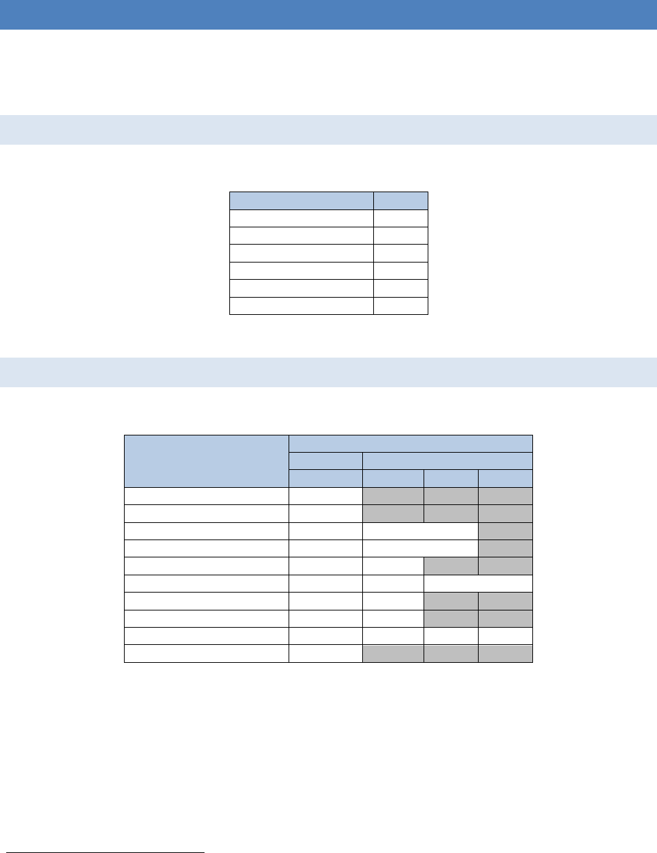
Figure 1
If any valid message is received by the tag within the first 100mS after announcing, then the tag will listen consider
the announce a success and listen for the full Awake Dwell before going to sleep. If no valid message is seen within
the ACK listen time then the tag will go to sleep for the Retry Dwell before attempting another announce. If The
Retry Count is reached, then the tag will listen for the full Awake Dwell regardless if a valid message is received in
the ACK listen time.
After an announce it is recommended to send a TAG_GO_TO_SLEEP operation as the last command to the
tag. This will save battery life by putting the tag back to sleep much sooner than the Awake Dwell would
allow.
1.3.2 Announce Reasons
Reason
Value
TIMEOUT
0x01
REQUESTED
0x05
RFID
0x06
EXIT_RESET
0x09
MACRO_EVENT
0x0A
BUTTON_1_PRESSED
0x10
Table 1
1.4 Requested Operations
Command
Value
Length
Raw Data Bytes1
0
1
2
3
TAG_DISPLAY_PAGE
0x20
Length (1)
Page
TAG_PAGES_LOADED
0x21
Length (1)
Total
TAG_PAGE_LIST
0x26
Length
List …
TAG_DISPLAY_TYPE
0x53
Length (1)
Display
Type
TAG_MAX_PAGES
0x54
Length (1)
Max
Pages
TAG_SLEEP_DWELL
0x22
Length (4)
Sleep Dwell Seconds
TAG_AWAKE_DWELL
0x23
Length (1)
Awake
Dwell
Seconds
TAG_RETRY_INTERVAL
0x29
Length (1)
Retry
Interval
mS
TAG_RETRY_COUNT
0x2A
Length (1)
Retry
Attempts
TAG_RF_CHANNEL
0x40
Length (1)
Channel
TAG_TX_POWER
0x41
Length (1)
Power
TAG_HW_VERSION
0x50
Length (1)
Rev
TAG_FW_VERSION
0x51
Length (8)
Board ID
Major
Rev
Minor
Rev
Year
TAG_BATTERY_LEVEL
0x52
Length (1)
Level
TAG_TEMPERATURE
0x55
Length (1)
Temp
TAG_LAST_RX_RSSI
0x43
Length (1)
RSSI
TAG_RFID_COUNT
0x45
Length (4)
Lifetime RFID Triggers
1
Multi-Byte data is Big Endian

TAG_AWAKE_TIME
0x49
Length (4)
Lifetime Awake Total
TAG_ANNOUNCE_COUNT
0x4A
Length (4)
Lifetime Announce Total
TAG_PAGE_FLIPS_COUNT
0x4B
Length (2)
Lifetime Page Flips
TAG_RESET_COUNT
0x57
Length (2)
Lifetime Resets

1.5 Commanded Operations
FW Name
OpCode
Length
Raw Data Bytes2
0
1
2
3
4
5
6
7
TAG_DISPLAY_PAGE
0x20
Length (1)
Page
TAG_DELETE_IMAGE
0x28
Length (1)
Page
TAG_IMAGE_LINE
0xA0
Length
Page
Line Number
Compression
Format3
Data
…
TAG_IMAGE_BLOCK
0xA1
Length
Page
X Coordinate
Y Coordinate
Compression Format
Data
…
TAG_TEMPLATE_WRITE
0xA8
Length
Page
Data
…
TAG_TEMPLATE_DATA
0xA9
Length
Page
Field #
Data
…
TAG_IMAGE_ASCII
0xA2
Length
Page
X Coordinate
Y Coordinate
Font Size
Data
…
TAG_WRITE_MEMORY
0xAA
Length
Page
Type4
Address
Data
…
TAG_SLEEP_DWELL
0x22
Length (4)
Sleep Dwell Seconds
TAG_TEMPORARY_SLEEP_DWELL
0x4C
Length (5)
Sleep Dwell Seconds
Number of
Announces
TAG_AWAKE_DWELL_SECONDS
0x23
Length (1)
Awake
Dwell
Seconds
TAG_AWAKE_DWELL_MILLI_SEC
0x4E
Length (2)
Awake Dwell
Milliseconds
TAG_RETRY_INTERVAL
0x29
Length (1)
Retry
Interval
mS
TAG_RETRY_COUNT
0x2A
Length (1)
Retry
Attempts
2
Multi-Byte data is Big Endian
3
Supported Compression Formats {0:None}
4
Supported Memory Types (0:RFU, 1:Image, 2:Macro}

TAG_DATA_REQUEST
0x33
Length
Requested
Tag 1
Requested
Tag 2
Requested
Tag …
TAG_RF_CHANNEL
0x40
Length (1)
Channel
TAG_TX_POWER
0x41
Length (1)
Power
SOFTWARE_RESET
0x5F
Length (0)
TAG_FIRMWARE_CRC
0xB1
Length
TAG_CRC
(0x01)
CRC5
TAG_COMPATIBLE_HW
(0x02)
Length
List…
TAG_FIRMWARE_DATA
0xB0
Length
Address
Data
…
TAG_FIRMWARE_ERASE_DATA
0xB2
Length (0)
TAG_SAVE_NVM
0x34
Length (0)
TAG_GO_TO_SLEEP
0x2C
Length (0)
BEACON_SLEEP_DWELL
0x4D
Length
Table 2
5
If fed a string of “123456789”, the calculated CRC should equal 0xCBF43926

2 FW UPGRADE
FW can be upgraded by using TAG_FIRMWARE_ERASE_DATA (0xB2), TAG_FIRMWARE_DATA (0xB0) and
TAG_FIRWMARE_CRC (0xB1) operations.
2.1 TAG_FIRMWARE_ERASE_DATA
This operation does not delete the running FW, but it deletes all previously downloaded FW from the external flash
buffer.
2.2 TAG_FIRWMARE_DATA
This operation allows binary data to be downloaded to the tag and stored in a buffer in external flash
2.3 TAG_FIRWMARE_CRC
This operation commands the tag to compute a CRC from the data previously downloaded into the external flash
buffer. If the CRC computed by the tag matches the CRC given with this operation, then the tag will erase and then
reprogram itself.
2.3.1 HW Configuration Compatibility
A list of compatible HW versions is downloaded with the CRC and indicates to the tag which versions the new FW
supports. This allows existing FW to refuse to update if the HW version is not supported even if the CRC
successfully matches.
Omni-ID, Inc Confidential Information Page | 10
3 TRIGGERS
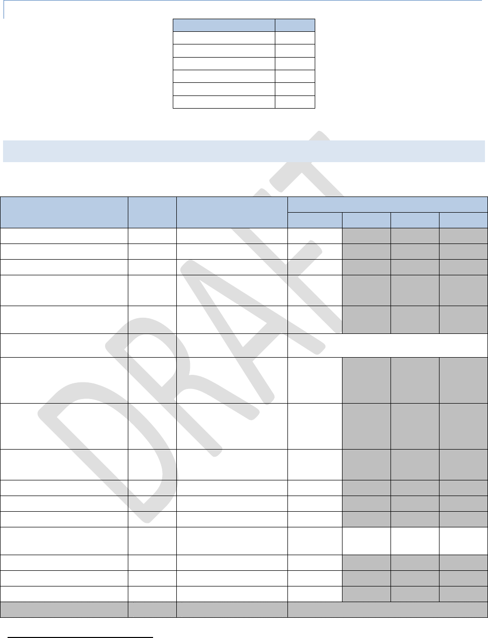
3.1 Magnetic Switch
The magnetic switch is primarily used to flip the image, but if it is held long enough a diagnostic screen is printed,
and if held even longer the tag will reset.
Figure 2
3.2 RFID
3.2.1 NXP IC (Gen 1 HW)
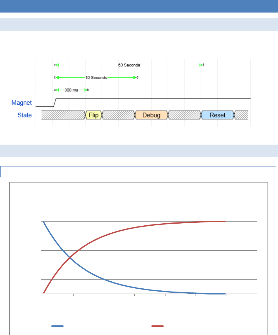
Figure 3
In existing Gen 1 HW with the NXP passive RFID IC, a dumb trigger is used to wake up the tag in the presence of a
865-928MHz signal. Because there can be many sources for this, the tag has to balance between a fast response
0
1000
2000
3000
4000
5000
6000
0 100 200 300 400 500 600 700
Time (mS)
Triggers
RFID Dynamic Back Off
Average Time Between Triggers Delay Between Announces
Omni-ID, Inc Confidential Information Page | 11
time and conserving power. To allow for this, a dynamic back off is used to increase the responsiveness of the tag.
In the presence of a constant RFID field, the tag is initially responsive but the time between announces will slowly
increase to a max value of 25 Seconds. Once 25 seconds has elapsed since the last RFID trigger, the back off time is
reset.
It is important to note that once the delay time has passed, the tag announces immediately upon being triggered.
This allows for immediate responsiveness when triggered, with a gradual back off to conserve energy.
Omni-ID, Inc Confidential Information Page | 12
3.2.2 Monza (Gen 1.5 HW)
The Monza allows communication over RFID by utilizing the user memory bank in the passive IC as a pass-through
to the micro.
3.2.2.1 Address Map
Table 3 describes the layout of memory in the User Bank of the Monza.
Word
I2C Byte
Description
Default
0d-3d
40d-47d
Active radio ID
00 00 00 00 00 00 00 00h
4d-5d
48d-51d
Firmware revision
00 00 00 00h
6d
52d
Operation Register
Word 32d
6d
53d
Response Register
Word 33d
7d
54d
Extended Data Registers
Word 34d
8d
56d-57d
Memory map type
EA 0Xh
9d
58d-73d
UUID
A0 BF DA F8 50 04 40 7C
A3 EA B8 0B AC C2 17 14h
Table 3
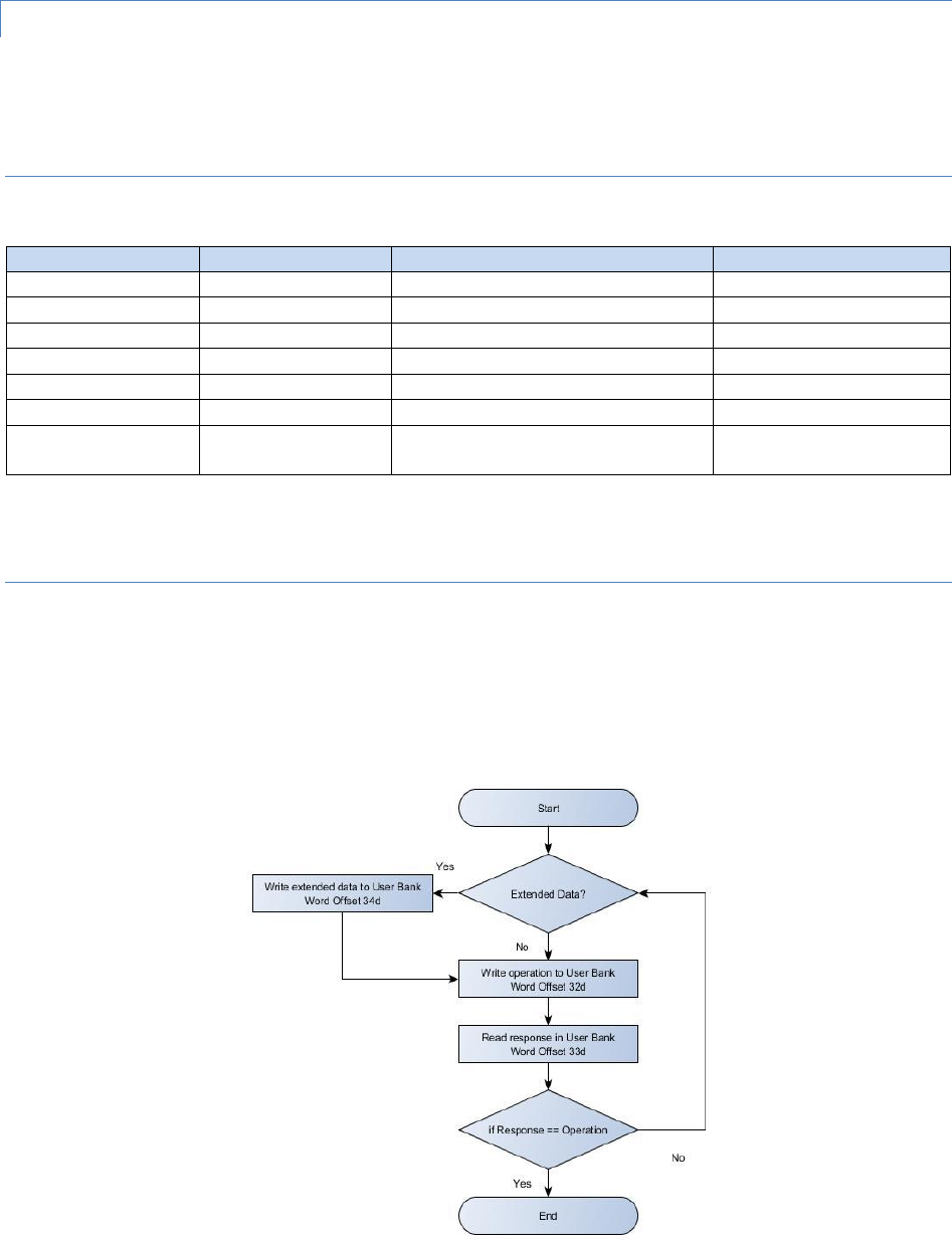
3.2.2.2 Algorithm
The flowchart in Figure 4 describes the method of commanding operations using the User Memory Bank of the
RFID interface as a pass through.
If successful, then the response register will contain a copy of the value written to the operation register.
Figure 4

Omni-ID, Inc Confidential Information Page | 13
3.2.2.3 RFID Opcodes
RFID opcodes allow a 2 byte interface into the tag.
Command
Word6
Response
High Byte
Low Byte
Display Page
0x20
Page
Delete Page
0x28
Page
Announce
0x30
0x00
Extended Data
0xFF
Data Byte
Length7
-1 = CRC mismatch
-2 = Length longer than buffer
Figure 5
3.2.2.3.1 Announce
An announce over the 433MHz interface can be triggered by writing 0x3000 to the Operation Register (32d).
3.2.2.4 Extended Opcodes
Extended data allows the existing 433MHz protocol to be used by tunneling through the RFID interface. An
additional 16-bit CRC after the commanded data is used to allow the micro to verify the data. Table 4 shows an
example of template data being commanded through the Monza.
Byte7
Use
Example
0
Data Body
Command
0xA9 (Template Data Cmd)
1
Page
1
2
Length
7
3
Field #
1
Template Data
4
Data 0
0x48 (‘H’)
…
…
0x45 (‘E’)
0x4C (‘L’)
0x4C (‘L’)
N
Data N
0x4F (‘0’)
N+1
Byte Stuff to force 16-bit boundary
0x00
N+2
CRC89
0x8C
N+3
0xA9
Table 4
3.2.2.4.1 Extended Opcode Response
6
Words are Big Endian
7
Maximum length is 100 Words (200 bytes)
8
CRC as described in section 3.2.2.5
9
CRC is Big Endian

Omni-ID, Inc Confidential Information Page | 14
If a response was requested through the extended data operation, then the extended response will be placed
starting at the Extended Data Register (34d). The first byte will be the byte length of the response.
3.2.2.5 CRC-CCITT
The CRC-CCITT algorithm is used, based on the polynomial shown in Equation 1.
Equation 1
It is seeded with 0xFFFF, and a reference string of “123456789” should produce a CRC of 0x29B1.
Omni-ID, Inc Confidential Information Page | 15
4 EVENT MACROS
Event macros allow a very limited scripting capability to handle event triggers. Each event is compared against a
lookup table that indicates the macro to execute. If no event is registered in the lookup table, then the default
action occurs (e.g. Button 1 announces, Button 2 flips the image).
4.1 Events
Event
Value
RFU
0x00
SYSTEM_RESET_EVENT
0x01
RFID_EVENT
0x02
BUTTON_1_EVENT
0x04
BUTTON_2_EVENT
0x05
EVENT_LOOKUP_END
0xFE
Table 5
4.2 Operations
Operation
Bytes10
Command
Extended Data
0
1
2
3
RFU
0x00
PAGE_FORWARD
0x01
MACRO_GOTO_ADDRESS
0x04
Address
MACRO_ANNOUNCE
0x07
Address if failed11
MACRO_DELAY
0x09
Seconds
MACRO_IF_PAGE_EQUALS
0x0A
Page
Address
MACRO_SET_PAGE
0x20
Page
MACRO_DELETE_PAGE
0x28
Page
MACRO_RADIO_MSG
0x70
Length
Data…
MACRO_END
0xFE
Table 6
10
Multi-Byte data is big Endian
11
Address to branch to if announce fails

Omni-ID, Inc Confidential Information Page | 16
4.3 Memory Layout
Error! Reference source not found. shows an example layout for the event macros. The header is used to indicate
to FW the formatting used as well as the complete length of the table. This is followed by the lookup table to link
the event with a specific macro address. The end of this table must contain the EVENT_LOOKUP_END operation.
12
Multi-Byte data is big Endian
Table 7
Byte12
Data
Example
Header
0
Version
1
1
Length to End
0x00
2
0x
3
RFU
0
Event Lookup Table
Event 1
4
Event
0x04 (Button 1)
5
Macro Address
12
0x00
6
0x0C
7
RFU
Event 2
8
Event
0x05 (Button 2)
9
Macro Address
26
0x00
10
0x1A
11
RFU
End
12
EVENT_LOOKUP_END
0xFE
Macros
Macro 1
13
MACRO_SET_PAGE
0x20
14
Page
1
15
MACRO_ANNOUNCE
0x07
16
Address to branch to if
Announce Failed
23
0x00
17
0x17
18
MACRO_SET_PAGE
0x20
19
Page
2
20
MACRO_GOTO_ADDRESS
0x04
21
Address
25
0x00
22
0x19
23
MACRO_SET_PAGE
0x20
24
Page
3
25
MACRO_END
0xFE
Macr
o 2
26
PAGE_FORWARD
0x01
27
MACRO_END
0xFE

Omni-ID, Inc Confidential Information Page | 17
5 TEMPLATES
The template is downloaded into flash along with the background image and dictates how Template Data is
formatted onto the display. This example uses two text fields of different sized text. Numbers larger than 8-bits
are Big Endian.
5.1 Template Fields
These are the different Field Types supported.
Field Type
OpCode
Byte 0
Byte 1
Byte 2
Byte 3
Byte 4
Byte 5
Byte 6
RFU
0x00
Text
0x01
X Coordinate
Y Coordinate
Font Size
Max Text
Length
Barcode
0x02
Starting X
Coordinate
Starting Y
Coordinate
Y Size
Max
Data
Length
Table 8
5.2 Template Data
Template Data is commanded through any interface (RF or RFID) and includes a Field number and data. The Field
number indicates which template field should be used to format the data. The example shown in Table 9 and
Table 13 is based on the example template in Table 11.
Text Field Example
Byte
Data
Example
0
Template Command
0xA9
1
Length (N – 1)
6
2
Page
1
3
Referenced Field Number
1
4
Data 0
0x48 (‘H’)
…
…
0x45 (‘E’)
0x4C (‘L’)
0x4C (‘L’)
N
Data N
0x4F (‘0’)
Table 9
Barcode Field Example
Byte
Data
Example
0
Template Command
0xA9
1
Length (N – 1)
10
2
Page
1
3
Referenced Field Number
2
4
Scale Size
2
5
Data 0
…
…
…

Omni-ID, Inc Confidential Information Page | 18
N
Data N
Table 10
5.3 Memory Layout
Byte
Data
Example
Header
0
Template Format
1
1
Number of Fields
2
2
Template Length
25
Field #0
3
Field Number
0
4
Field Type
0x01 (Text)
5
X Coordinate
85
0x00
6
0x55
7
Y Coordinate
130
0x00
8
0x82
9
Font Size
4 (32x32 Pixel characters)
10
Max Text Length
10
Field #1
12
Field Number
1
13
Field Type
0x01 (Text)
14
X Coordinate
40
0x00
15
0x28
16
Y Coordinate
230
0x00
17
0xE6
18
Font Size
6 (48x48 Pixel characters)
19
Max Text Length
3
Field #2
20
Field Number
2
21
Field Type
0x02 (Barcode)
22
Starting X Coordinate
20
0x00
23
0x14
24
Starting Y Coordinate
200
0x00
25
0xC8
26
Y Size (in pixels)
16
0x00
27
0x10
28
Max Data Length
10
0x0A
Table 11
5.4 Commands
Templates are located within the image address space, so it is important to follow the proper flow.
1.) Delete Page
2.) Download Image if required (e.g. TAG_IMAGE_LINE, TAG_IMAGE_BLOCK)
3.) Download Template (e.g. TAG_TEMPLATE_WRITE)
4.) Download dynamic data for the fields (e.g. TAG_TEMPLATE_DATA)

Omni-ID, Inc Confidential Information Page | 19
5.) Flip to page to generate the new image
5.5 Limitations
Maximum of 10 Fields
Each Field can have a maximum of 20 bytes of data
Maximum template size of 100 bytes
FW only holds the dynamic data for one page at a time. Flipping to any other page results in dynamic data
previously downloaded via the TAG_TEMPLATE_DATA

Omni-ID, Inc Confidential Information Page | 20
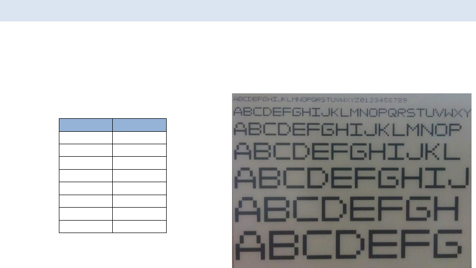
6 TEXT RENDERING
6.1 Character Set
Supported ASCII characters are listed in Table 12. All other characters will be displayed as a checkered pattern:
Character
Hex
Dec
Character
Hex
Dec
Character
Hex
Dec
Character
Hex
Dec
0
0x30
48
I
0x49
73
b13
0x62
98
u13
0x75
117
1
0x31
49
J
0x4A
74
c13
0x63
99
v13
0x76
118
2
0x32
50
K
0x4B
75
d13
0x64
100
w13
0x77
119
3
0x33
51
L
0x4C
76
e13
0x65
101
x13
0x78
120
4
0x34
52
M
0x4D
77
f13
0x66
102
y13
0x79
121
5
0x35
53
N
0x4E
78
g13
0x67
103
z13
0x7A
122
6
0x36
54
O
0x4F
79
h13
0x68
104
7
0x37
55
P
0x50
80
i13
0x69
105
8
0x38
56
Q
0x51
81
j13
0x6A
106
9
0x39
57
R
0x52
82
k13
0x6B
107
:
0x3A
58
S
0x53
83
i13
0x6C
108
A
0x41
65
T
0x54
84
m13
0x6D
109
B
0x42
66
U
0x55
85
n13
0x6E
110
C
0x43
67
V
0x56
86
o13
0x6F
111
D
0x44
68
W
0x57
87
p13
0x70
112
E
0x45
69
X
0x58
88
q13
0x71
113
F
0x46
70
Y
0x59
89
r13
0x72
114
G
0x47
71
Z
0x5A
90
s13
0x73
115
H
0x48
72
a13
0x61
97
t13
0x74
116
Table 12
13
Lowercase letters are replaced with Uppercase letters when displayed
Omni-ID, Inc Confidential Information Page | 21
6.2 Character Font Size
A scalable 8-pixel font is used allowing multiple font sizes. Table 13 shows a range of font sizes with their
correlating pixel size.
Font Size
Pixel Size
1
8x8
2
16x16
3
24x24
4
32x32
5
40x40
6
48x48
7
56x56
N
…
Table 13
Figure 6
Omni-ID, Inc Confidential Information Page | 22
7 EXTERNAL FLASH
7.1 Memory Map
Address
2.7”
264 x 176 Pixel
4.41”
400 x 300 Pixel
RFU
(32KB)
0x00000
0x07FFF
Scratch
Pad
(32KB)
0x08000
0x0FFFF
Images
(384KB)
0x10000
Page 1
Page 1
0x11FFF
0x12000
Page 2
0x13FFF
…
…
…
0x6C000
Page 47
Page 24
0x6DFFF
0x6E000
Page 48
0x6FFFF
Log
(64KB)
0x70000
0x7FFFF
Table 14
7.2 Space Between Images
Address
Offset
2.7”
264 x 176 Pixel
4.41”
400 x 300 Pixel
Page
0x0000
Page 1 Image
Page 1 Image
0x16AF
0x16B0
Image Dirty Byte
0x16B1
Template Dirty Byte
0x16B2
RFU
0x16BF
0x16C0
Template Space
0x1FFF
0x2000
0x3A97
0x3A99
Image Dirty Byte
0x3A9A
Template Dirty Byte
0x3A9B
RFU
0x3AA7
0x3AA8
Template Space
0x3FFF
Table 15

Omni-ID, Inc Confidential Information Page | 23
7.2.1 Image Dirty Byte
The image dirty byte is set to flag if the image is valid. It is also used to flag if the space is still valid and being used
for other purposes, such as memory storage, but should not be displayed.
Value
Meaning
0x00
RFU
0x01
Valid Image
0xFF
No Valid Image
Table 16
7.2.2 Template Dirty Byte
The template dirty byte is set to flag if there is a valid template that needs to be processed on an image update.
Value
Meaning
0x00
RFU
0x01
Valid Template
0xFF
No Valid Template
Table 17

Omni-ID, Inc Confidential Information Page | 24
8 EVENT LOG
8.1 Overview
Events are logged to external flash (see Table 14 for address) serially. An event is triggered when a preset
threshold is reached. For example, every 100 announces a LOG_ANNOUNCE is saved in the event log. Combined
with a LOG_TIMESTAMP saved once per day, this gives a fairly detailed account of the tag’s life.

Omni-ID, Inc Confidential Information Page | 25
8.2 Cheat Sheet
REASON
Default
Cadence
Max
Lifetime
Expected
Max
Expected
Log Size
Raw Data Bytes14
Notes
Code
1
2
3
4
5
6
7
8
0
LOG_RFU
0x00
Reserved
LOG_HEADER
0x01
Log
Version
LOG_TIMESTAMP
Every 1
Day
5 Years
1825
0x02
Time in seconds
LOG_ANNOUNCE
100
285,000
2850
0x03
LOG_ANNOUNCE_NO_ACK
200
2,900,000
14,500
0x04
LOG_PAGE_FLIP
Every 10
120,000
12,000
0x05
LOG_RADIO_ON_TIME
Every 5
Minutes
8,333
Minutes
1,666
0x06
Time in seconds
LOG_TRIGGER_COUNT
200
2,900,000
14,500
0x07
LOG_FW_VERSION
1
5
20
0x08
FW Version (App
Type, Major Rev,
Minor Rev, Sub Rev)
LOG_RESET_POWER_ON
1
5
5
0x09
Separate from
LOG_RESET_REASON so we
can distinguish brown out
resets
LOG_RESET_REASON
1
5
20
0x0A
Reason15
LOG_FLASH_ON_TIME
0x0E
LOG_CHANGE_TH_TIMESTAMP
1
5 Years
20
0x72
New Threshold
LOG_CHANGE_
TH_ANNOUNCE_NO_ACK
1
5
5
0x73
New
Threshold
LOG_CHANGE_
1
5
5
0x74
New
14
Multi-Byte data is stored little Endian
15
Reasons {0:RFU, 1:Unused, 2:Unexpected RF Interrupt, 3:FW Update, 4:Requested, 5:MagSwitch/Button, 6:Unexpected Interrupt}

Omni-ID, Inc Confidential Information Page | 26
TH_ANNOUNCE_NO_ACK
Threshold
LOG_CHANGE_ TH_PAGE_FLIP
1
5
5
0x75
New
Threshold
LOG_CHANGE_ TH_RADIO_ON_TIME
1
5
20
0x76
New Threshold
LOG_CHANGE_ TH_TRIGGER_COUNT
1
5
5
0x77
New
Threshold
LOG_CHANGE_TH_RESET
1
5
5
0x79
New
Threshold
LOG_CHANGE_TH_FLASH
0x7E
New Threshold
LOG_CHANGE_NAH_TIMESTAMP
1
5
40
0x42
New nAh per second
LOG_CHANGE_NAH_PAGE_FLIP
1
5
40
0x45
New nAh per tick
LOG_CHANGE_NAH_RADIO_ON_TIME
1
5
40
0x46
New nAh per second
LOG_CHANGE_NAH_FLASH_ON_TIME
0x4E
New nAh per second
LOG_UNUSED
0xFF
Table 18

Omni-ID, Inc Confidential Information Page | 27
8.3 Log Header
The log header is used to indicate that the logging format was changed. This allows FW updates in the field that
impact the event logger without negating the old log data.
8.4 LOG_CHANGE_
The LOG_CHANGE_ operations allow changes in the hardcoded thresholds and expected nAh battery usage to be
logged. This allows FW to parse the log at runtime and react to threshold and power differences between FW
updates.

Omni-ID, Inc Confidential Information Page | 28
9 INTERNAL FLASH
9.1 Address Map
Address
Uses
Info D
(Calibration)
0x1800
Type 0
Type 1
Type 2
0x1801
0x1802
UID
UID
UID
0x1803
0x1804
0x1805
0x1806
0x1807
0x1808
0x1809
0x180A
RfFreq2
RfFreq2
RfFreq2
0x180B
RfFreq1
RfFreq1
RfFreq1
0x180C
RfFreq0
RfFreq0
RfFreq0
0x180D
RfMaxPower
RfMaxPower
RfMaxPower
0x180E
HwVersion
HwVersion
…
0x187F
Info C
(Parameters)
0x1880
Type 0
Type 1
Type 2
Type 3
Type 4
0x1881
0x1882
SleepDwell
SleepDwell
SleepDwell
SleepDwell
SleepDwell
0x1883
0x1884
0x1885
0x1886
AwakeDwell
AwakeDwell
AwakeDwell
AwakeDwell
0x1887
RetryInterval
RetryInterval
RetryInterval
RetryInterval
RetryInterval
0x1888
BeaconPeriod
BeaconPeriod
BeaconPeriod
0x1889
0x188A
FamilyValue
FamilyValue
FamilyValue
0x188B
0x188C
DomainValue
DomainValue
DomainValue
AwakeTime

Omni-ID, Inc Confidential Information Page | 29
0x188D
0x188E
0x188F
0x1890
BeaconCount
BeaconCount
BeaconCount
BeaconCount
0x1891
0x1892
0x1893
0x1894
CurrentPage
CurrentPage
CurrentPage
CurrentPage
CurrentPage
0x1895
RetryCount
RetryCount
RetryCount
RetryCount
RetryCount
0x1896
RfChannel
RfChannel
RfChannel
RfChannel
RfChannel
0x1897
TxPower
TxPower
TxPower
TxPower
TxPower
0x1898
RFIDTriggerCount
RFIDTriggerCount
RFIDTriggerCount
0x1899
0x189A
0x189B
0x189C
WatchdogExpireCount
WatchdogExpireCount
WatchdogExpireCount
0x189D
0x189E
0x189F
0x18A0
awakeTimeCount
awakeTimeCount
0x18A1
0x18A2
0x18A3
0x18A4
announceCount
announceCount
0x18A5
0x18A6
0x18A7
0x18A8
pageFlipCount
pageFlipCount
0x18A9
0x18AA
button1Presses
0x18AB
0x18AC
0x18AD
0x18AE
button2Presses
0x18AF
0x18B0

Omni-ID, Inc Confidential Information Page | 30
0x18B1
…
0x18FF
Info B
(Debug)
0x1900
ResetCount
0x1901
0x1902
FailureCode
0x1903
0x1904
StateTransition
0x1905
State
0x1906
OTState
…
0x197F
Info A
0x1980
0x19FF

Omni-ID, Inc Confidential Information Page | 31
9.2 Calibration Data “.infoD”
Unused
9.3 HW Configuration
HW Configuration is set at manufacturing and allows a single base FW to decide at run time which HW options to
utilize. For example, the micro must know if the mag switch is populated or not and can determine this by the HW
Configuration version.
Product
Version
Value
Magswitch
Buttons
Prototypes Never
in Production
In Production
Notes
P3
A1
0x01
NO
NO
P3
A2
0x02
YES
NO
X
P3
A3
0x03
YES
YES
Inverted Discharge
Inverted LED & Button
input
P3
A4
0x04
YES
YES
X
Inverted Discharge
P3
A5
0x05
YES
NO
X
Monza (I2C)
Display Power moved.
Flash Power Enable
added.
P3
A6
0x06
YES
YES
X
P4
A1
0x11
NO
NO
X
P4
A2
0x12
YES
NO
X
P4
A3
0x13
YES
YES
X
P4
A5
0x14
YES
NO
Monza (I2C)
Display Power moved.
Flash Power Enable
added.
P4
A6
0x15
YES
YES
L3
A1
0x21
L4
A1
0x31
Table 19

Omni-ID, Inc Confidential Information Page | 32
10 POWER MEASUREMENTS
Power usage is tracked in FW to allow an estimation of battery life remaining. This value is a very rough estimate
based on typical power measurements, and only accounts for power used in a few operations.
10.1 Revision 01.03.00.00
Monitored
Measured
Calculated in FW
Current
mAh
nAh
Page Flip
-
0.01555555
15700 per Flip
Standby
2.8uA
0.00000077
2 per Second
Standby In constant RFID
10uA
0. 00000277
Radio On Time
-
0.00529288
5300 per Second
Flash On Time
19mA
0.00527777778
5300 per Second
Reset per mS
1.378mA Running no flash
20uA Flash on in sleep
18.2mA flash on no read
18.5mA flash on constant read
20.6 flash write
Omni-ID, Inc Confidential Information Page | 33
FCC Compliance
This device complies with part 15 of the FCC Rules. Operation is subject to the
following two conditions:
(1) This device may not cause harmful interference, and (2) this device must accept any
interference received, including interference that may cause undesired operation.
Note: This equipment has been tested and found to comply with the limits for a Class
A digital device, pursuant to part 15 of the FCC Rules. These limits are designed to
provide reasonable protection against harmful interference when the equipment is
operated in a commercial environment. This equipment generates, uses, and can
radiate radio frequency energy and, if not installed and used in accordance with the
instruction manual, may cause harmful interference to radio communications.
Operation of this equipment in a residential area is likely to cause harmful interference
in which case the user will be required to correct the interference at his own expense.
Industry Canada Compliance
This device complies with Industry Canada license-exempt RSS standard(s). Operation
is subject to the following two conditions:
(1) this device may not cause interference, and
(2) this device must accept any interference, including interference that may cause
undesired operation of the device.
Le présent appareil est conforme aux CNR d'Industrie Canada applicables aux appareils
radio exempts de licence. L'exploitation est autorisée aux deux conditions suivantes :
(1) l'appareil ne doit pas produire de brouillage, et
(2) l'utilisateur de l'appareil doit accepter tout brouillage radioélectrique subi, même si
lebrouillage est susceptible d'en compromettre le fonctionnement.
Under Industry Canada regulations, this radio transmitter may only operate
using an antenna of a type and maximum (or lesser) gain approved for the
transmitter by Industry Canada.
To reduce potential radio interference to other users, the antenna type and its
gain should be so chosen that the equivalent isotropically radiated power
(e.i.r.p.) is not more than that necessary for successful communication.
Conformément à la réglementation d'Industrie Canada, le présent émetteur
radio peut fonctionner avec une antenne d'un type et d'un gain maximal (ou
inférieur) approuvé pour l'émetteur par Industrie Canada.
Dans le but de réduire les risques de brouillage radioélectrique à l'intention des
autres utilisateurs, il faut choisir le type d'antenne et son gain de sorte que la
puissance isotrope rayonnée équivalente (p.i.r.e.) ne dépasse pas l'intensité
nécessaire à l'établissement d'une communication satisfaisante.
Omni-ID, Inc Confidential Information Page | 34
This radio transmitter 10336A-VIEW4 has been approved by Industry Canada to
operate with the antenna types listed below with the maximum permissible gain and
required antenna impedance for each antenna type indicated. Antenna types not
included in this list, having a gain greater than the maximum gain indicated for that
type, are strictly prohibited for use with this device.
Le présent émetteur radio (identify the device by certification number, or model
number if Category II) a été approuvé par Industrie Canada pour fonctionner avec les
types d'antenne énumérés ci-dessous et ayant un gain admissible maximal et
l'impédance requise pour chaque type d'antenne. Les types d'antenne non inclus dans
cette liste,
ou dont le gain est supérieur au gain maximal indiqué, sont strictement interdits pour
l'exploitation de l'émetteur.
Copyright ©2015 Omni-ID, Cayman, Ltd. All rights reserved.
The information in these pages are furnished for informational use only, are subject to
change without notice, and should not be construed as a commitment by Omni-ID,
Cayman, Ltd.
Omni-ID, Cayman, Ltd. assumes no responsibility or liability for any errors or
inaccuracies. Every effort has been made to supply complete and accurate information.
Omni-ID assumes no responsibility for its use, or for any infringements of patents or
other rights of third parties, which would result.
Omni-ID
1200 Ridgeway Ave.
Suite 106
Rochester, NY 14615
www.omni-id.com