Panasonic of North America TUWHR1U 2.4 GHz and 60 GHz Wireless HD Unit User Manual tc p54z1 eng 2488 indb
Panasonic Corporation of North America 2.4 GHz and 60 GHz Wireless HD Unit tc p54z1 eng 2488 indb
UserManual.wiki
>
Panasonic of North America
>
TUWHR1U User Manual
User Manual
Navigation menu
Upload a User Manual
Namespaces
Wiki Guide
HTML
PDF
Info
Views
User Manual
Discussion / Help
Navigation
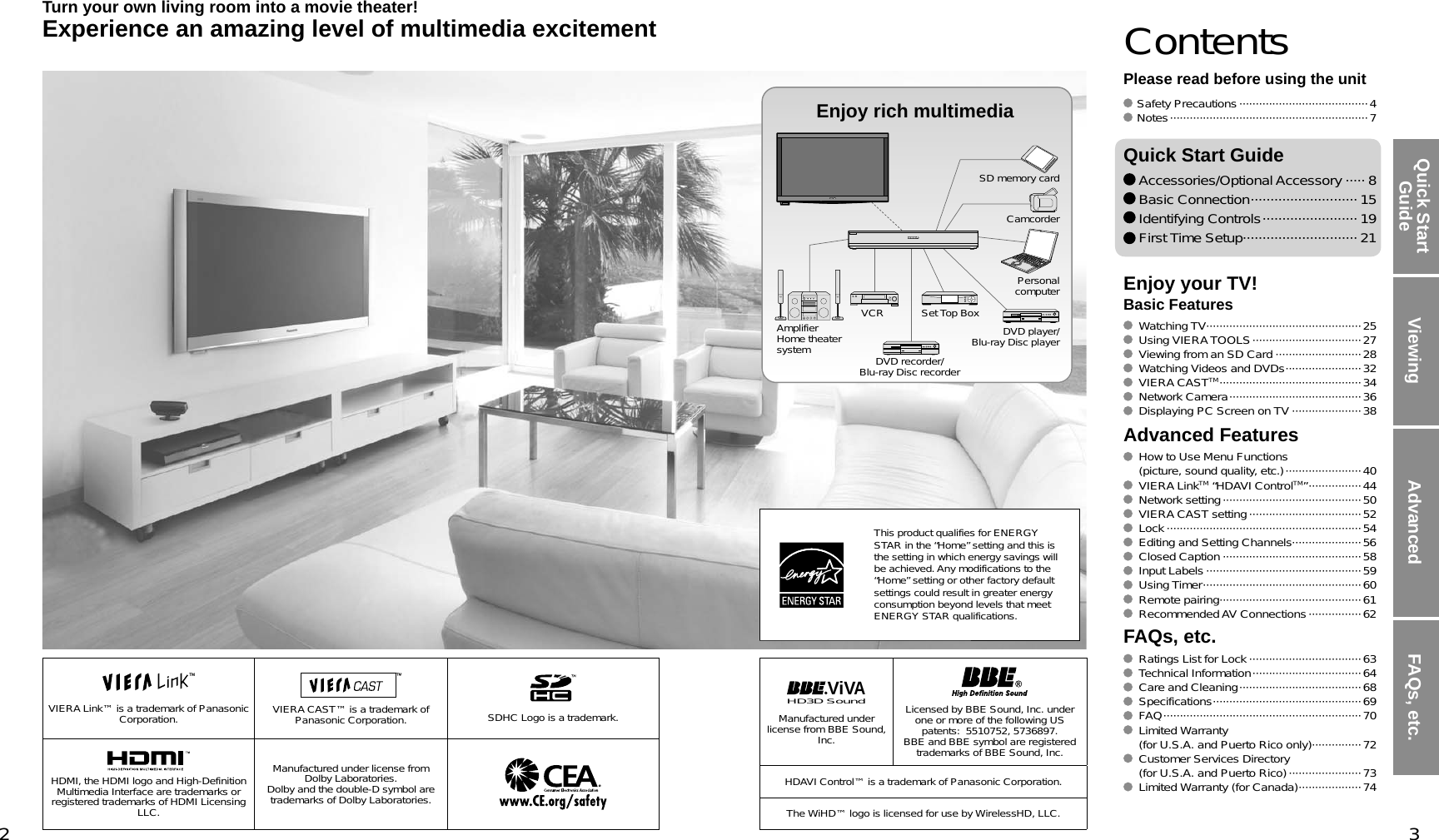
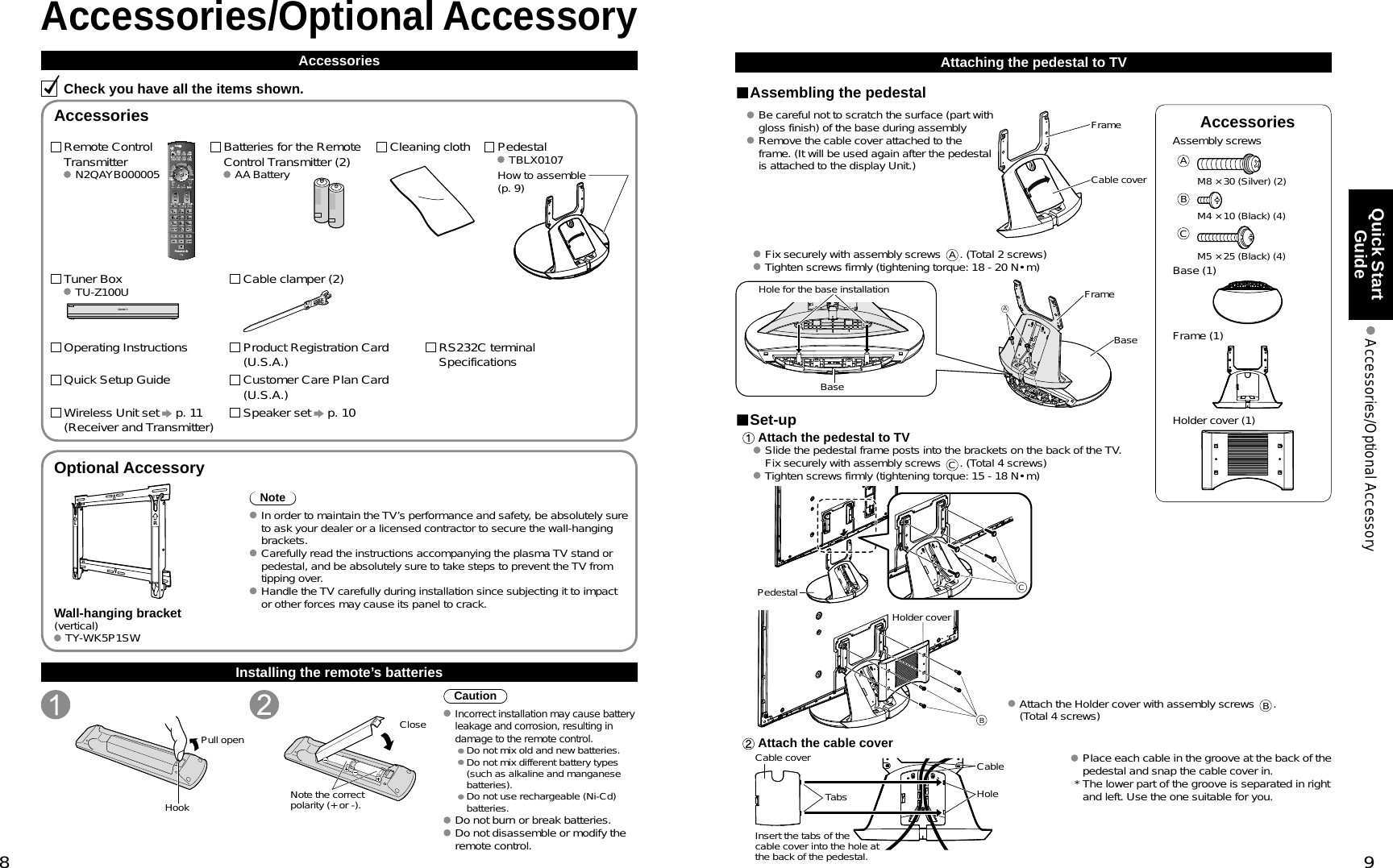
![10 11Quick Start Guide Accessories/Optional AccessoryAccessoriesSpeaker (2) SP-54Z1UMounting bracket [Top] (2) TXFKR04DLUJ [Bottom] (2) TXFKR02DLUJFrontBackAssembly screws (16) THEC134ZSpeaker cable TXJ/SPDKUJAccessoriesAssembly screws (3) TXFXY01JSUJAABM4 × 10 (2) M5 × 10 (1)HDMI cable K1HY19YY00069.8 ft (3.0 m)Exclusive cable for Wireless Unit TXFMM01JSUJExclusive cable for Wireless Receiver1.6 ft (0.5 m)Exclusive cable for Wireless Transmitter3.3 ft (1.0 m)Cable clamper (2) TMME364Wireless Unit (Receiver) TU-WHR1UWireless Unit (Transmitter) TU-WHT1UAccessories/Optional Accessory(Continued)Attaching the pedestal to TV (continued)Attaching the pedestal to TVWarningDo not disassemble or modify the pedestal. Otherwise the TV may fall over and become damaged, and personal injury may result.CautionDo not use any other TV and displays. Otherwise the TV may fall over and become damaged, and personal injury may result.Do not use the pedestal if it becomes warped or physically damaged. If you use the pedestal when it is physically damaged, personal injury may result. Contact your nearest Panasonic Dealer immediately.During set-up, make sure that all screws are securely tightened. If sufficient care is not taken to ensure screws are properly tightened during assembly, the pedestal will not be strong enough to support the TV, and it might fall over and become damaged, and personal injury may result.Attaching the Speaker to TV Fix the Mounting bracket securely to the back of the Display unit with Assembly screws (total 16 screws). Insert the speaker mounting screws temporarily in the screw outermost holes of the speaker and fix the speaker mounting screws to the speaker mounting bracket.Orient the front side of the Mounting bracket toward the rear side of the speaker and display Unit side. Fix it same as the speaker at the other side. There will be a gap between the Display Unit and the speaker.Mountingbracket[Bottom]AssemblyscrewsBack of Display UnitMounting bracket[Top]AssemblyscrewsBack of Display UnitSpeakerPlace the temporarily inserted screws into the counter sunk holes on the bracket Connect Display Unit and speaker with speaker cable. Fix it in the same way as the speaker on the other side. Lower right (Back of Display Unit)Speaker cableSpeakerNote Tighten the screws firmly. Insert to the end of the speaker cable terminal firmly. Loosen the screw shown in fig. A above to adjust the gap between the speaker and the display Unit. Do not hold the speaker to transport the unit.Connecting Display Unit, Tuner Box and Wireless UnitWired connection Connect Display Unit to Tuner BoxHDMI AV OUTHDMI AV OUTDisplay UnitTuner BoxHDMI CableWireless connection Connect Wireless Unit (Receiver) to Display UnitExclusive cable for Wireless ReceiverHole for Cable clamperRemove this screw when attaching the speaker.Insert the metal tab on the top of the Wireless Unit (Receiver) into the groove of the display Unit.Insert the tabs on the front of the Wireless Unit (Receiver) into the holes at the back of the Display Unit.Assembly screws BAssembly screws AFix securely with assembly screws (Total 3 screws). Caution Do not disassemble or modify the Wireless Unit.](https://usermanual.wiki/Panasonic-of-North-America/TUWHR1U/User-Guide-1086679-Page-6.png)
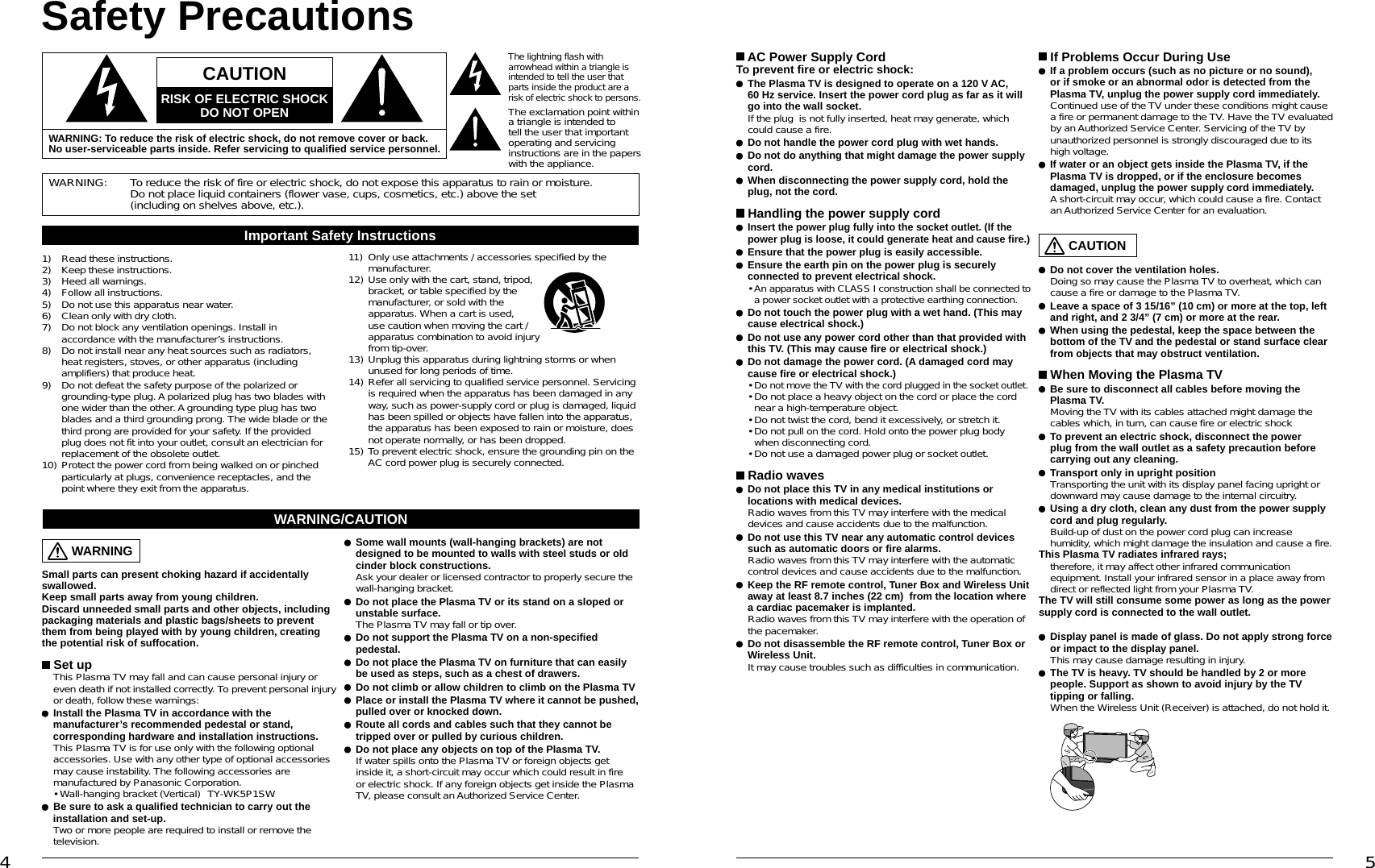
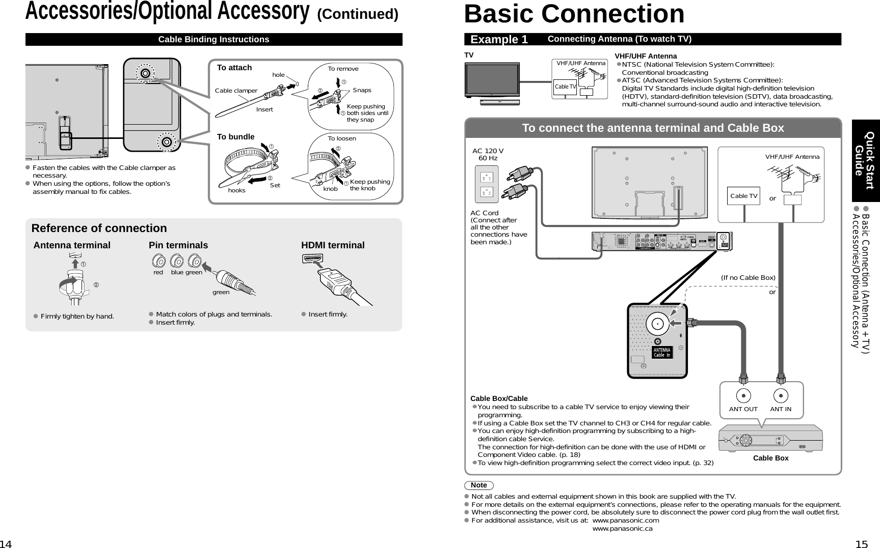
![12 13Quick Start Guide Accessories/Optional AccessoryAccessories/Optional Accessory(Continued)Installing the Display Unit and Tuner BoxNote Do not connect any other device than Wireless Unit to the HDMI terminal of the Display Unit/Tuner Box. If the connection is not correct, the following icons will be displayed when the Display unit and the Tuner box are turned on.Precautions for Wireless UnitTransmission RangeUse the Wireless Unit (Transmitter) within a straight line distance of 10 m (approx.) from the Wireless Unit (Receiver).The range may be shortened if there are any obstacles or the surrounding environment or building structure affects the transmission.Installation EnvironmentDo not install this apparatus in the following locations to avoid distortion of image or audio or unit failure due to the radio performance degradation. Location subject to be high temperature (near the heater etc.) Location with poor air circulation (at the end of a closed rack etc.)In the following cases, the image or audio may be distorted or intermittent, or the apparatus may not operate properly:There is a strong obstacle for the radio waves between the Wireless Unit (Transmitter) and Wireless Unit (Receiver). (furniture, AV devices, rack, rack door etc.) Wireless Unit (Transmitter) is not facing the Wireless Unit (Receiver). Wireless Unit (Transmitter) is placed significantly far from the front of Wireless Unit (Receiver) direction.(Especially in a high position near the TV display, behind the TV, behind the right side of the pedestal)Interference from Other DevicesIf the Wireless Unit (Transmitter)/Wireless Unit (Receiver) is too close to other devices, failures such as malfunction or slow remote control response may occur due to the radio wave interference. Keep the transmitter away from the following devices as much as possible: Wireless LAN, Microwaves, Telephones, Other electric devices Connect Wireless Unit (Transmitter) to Tuner BoxExclusive cable for Wireless TransmitterHole for Cable clamperCable Binding for Wireless Unit Wireless Unit (Receiver) Wireless Unit (Transmitter)Attach to hole for Cable clamper Unlock it and connect the AV cable out of the Exclusive cable for Wireless Receiver/Transmitter. Fix the cable so that it will not become unplugged.40°5°approx. 10 mThe angle of the transmitter can be adjusted to 40º upward and 5º downward.Top View[Horizontal Direction]Side View80°80°10m5m5m ReceiverDisplayTransmitter[Vertical Direction]Floor5m5mDisplay 45°45°TransmitterReceiverThis Display Unit is connected to a device other than Tuner Box.](https://usermanual.wiki/Panasonic-of-North-America/TUWHR1U/User-Guide-1086679-Page-7.png)
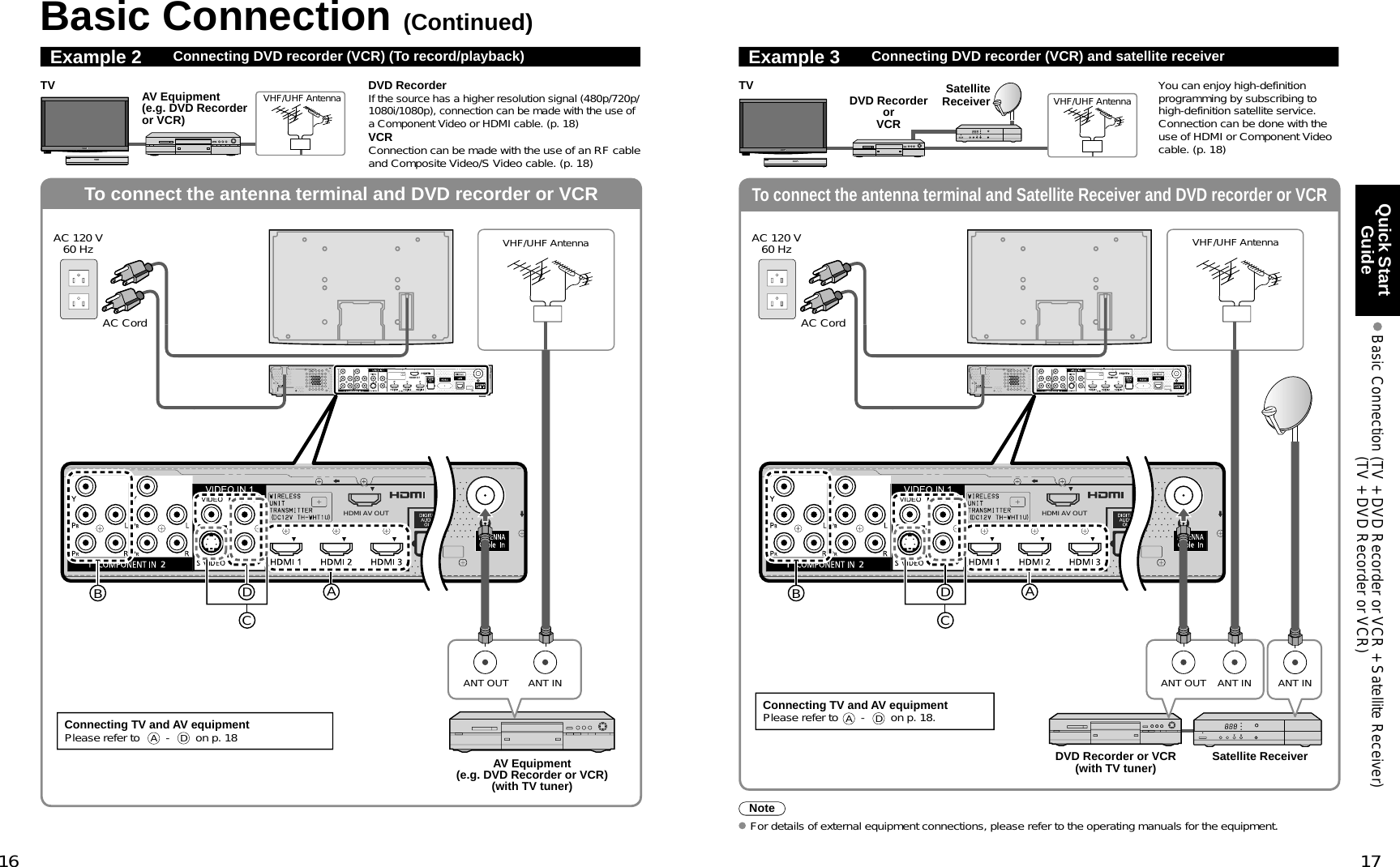
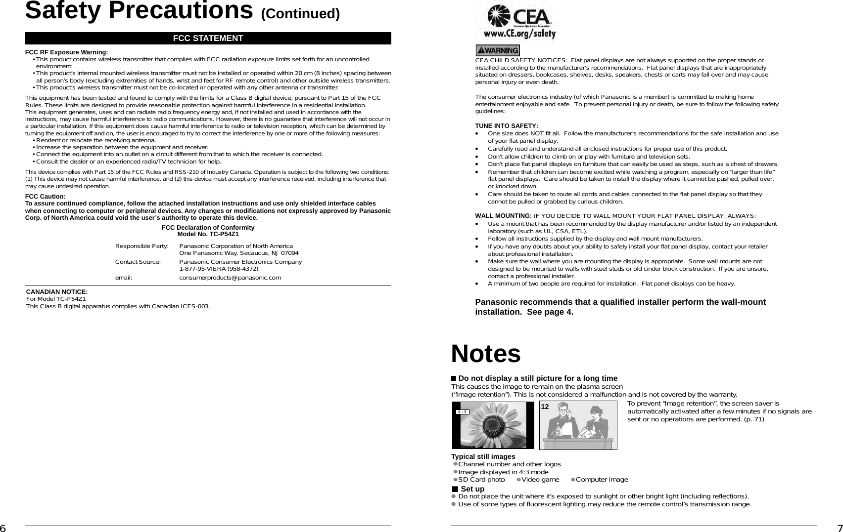
![68 69FAQs, etc. Specifications Technical Information Care and CleaningTC-P54Z1Power Source AC 120 V, 60 HzPowerConsumptionMaximum Display Unit: *** W / Tuner Box: *** W (Wireless Unit (Receiver) 12 W / Wireless Unit (Transmitter) 10 W)Standby condition Display Unit: *.* W / Tuner Box: *.* WPlasmaDisplay panelDrive method AC typeAspect Ratio 16:9Visible screen size(W × H × Diagonal)(No. of pixels) 54 ” class (54.1 inches measured diagonally)47.1 ” × 26.5 ” × 54.1 ” (1,198 mm × 673 mm × 1,473 mm)2,073,600 (1,920 (W) × 1,080 (H)) [5,760 × 1,080 dots]SoundAudio Output 20 W [(3 W + 7 W) × 2] (10 % THD)PC signals VGA, SVGA, XGA, WXGA, SXGA Horizontal scanning frequency 31 - 69 kHzVertical scanning frequency 59 - 86 HzChannel Capability(Digital/Analog) VHF/UHF: 2 - 69, CATV: 1 - 135Operating Conditions Temperature: 32 °F – 104 °F (0 °C – 40 °C) Humidity: 20 % – 80 % RH (non-condensing)Connection TerminalsVIDEO IN 1 VIDEO: RCA PIN Type × 1 1.0 V [p-p] (75 )S-VIDEO: Mini DIN 4-pin Y: 1.0 V [p-p] (75 ) C: 0.286 V [p-p] (75 )AUDIO L-R: RCA PIN Type × 2 0.5 V [rms]VIDEO IN 2 VIDEO: RCA PIN Type × 1 1.0 V [p-p] (75 )AUDIO L-R: RCA PIN Type × 2 0.5 V [rms]COMPONENT IN 1-2 Y: 1.0 V [p-p] (including synchronization)PB, PR: ±0.35 V [p-p]AUDIO L-R: RCA PIN Type × 2 0.5 V [rms]HDMI 1-4 TYPE A Connector × 4• This TV supports “HDAVI Control 4” function.PC D-SUB 15PIN: R,G,B / 0.7 V [p-p] (75 ) HD, VD / 1.0 - 5.0 V [p-p] (high impedance)RS232C (Serial) D-sub 9pin for external controlLAN (for VIERA CAST IPTV)RJ45 (10BASE-T/100BASE-TX)Card slot SD CARD slot × 1AUDIO OUT AUDIO L-R: RCA PIN Type × 2 0.5 V [rms]DIGITAL AUDIO OUT PCM / Dolby Digital, Fiber OpticFEATURES 3D Y/C FILTER CLOSED CAPTION V-Chip IPTV (VIERA CAST)Photo viewer Movie player HDAVI Control 4Dimensions( W × H × D )DisplayUnitIncluding pedestal 56.3” × 35.2” × 15.0” (1,428 mm × 893 mm × 379 mm)Display Unit only 56.3” × 32.3” × 1.0” (1,428 mm × 820 mm × 25 mm)Tuner Box 17.0” × 2.4” × 9.8” (430 mm × 59 mm × 240 mm)Wireless Unit (Transmitter)Wireless Unit (Receiver)7.5” × 2.8” × 2.8” (190 mm × 69 mm × 70 mm)5.8” × 5.3” × 1.9” (146 mm × 133 mm × 46 mm)MassDisplayUnitIncluding pedestal 83.8 lb (38.0 )Display Unit only 70.6 lb (32.0 )Tuner Box 6.7 lb (3.0 )Wireless Unit (Transmitter)Wireless Unit (Receiver)0.7 lb (280 )0.9 lb (400 )167839451015141312112Technical Information (Continued)Care and CleaningFirst, unplug the Power cord plug from the wall outlet.Display panelThe front of the display panel has been specially treated. Wipe the panel surface gently using only a cleaning cloth or a soft, lint-free cloth. If the surface is particularly dirty, soak a soft, lint-free cloth in diluted mild liquid dish soap (1 part mild liquid dish soap diluted by 100 times the amount of water) and then wring the cloth to remove excess liquid. Use this cloth to wipe the surface of the display panel, then wipe it evenly with a dry cloth of the same type until the surface is dry. Do not scratch or hit the surface of the panel with fingernails or other hard objects. Furthermore, avoid contact with volatile substances such as insect sprays, solvents, and thinner; otherwise, the quality of the surface may be adversely affected.CabinetIf the cabinet becomes dirty, wipe it with a soft, dry cloth. If the cabinet is particularly dirty, soak the cloth in a weak mild liquid dish soap and then wring the cloth dry. Use this cloth to wipe the cabinet and then wipe it dry with a dry cloth. Do not allow any mild liquid dish soap to come into direct contact with the surface of the Plasma TV. If water droplets get inside the unit, operating problems may result. Avoid contact with volatile substances such as insect sprays, solvents, and thinner; otherwise, the quality of the cabinet surface may be adversely affected or the coating may peel off. Furthermore, do not leave it for long periods in contact with articles madefrom rubber or PVC.PedestalCleaning Wipe the surfaces with a soft, dry cloth. If the unit is particularly dirty, clean it using a cloth soaked with water to which a small amount of mild liquid dish soap has been added and then wipe with a dry cloth. Do not use products such as solvents, thinner, or household wax for cleaning, as they can damage the surface coating. (If using a chemically-treated cloth, follow the instructions supplied with the cloth.)Do not attach sticky tape or labels, as they can make the surface of the pedestal dirty. Do not allow long-term contact with rubber, vinyl products, or the like. (Doing so will cause deterioration.)Wireless Unit Wipe the glossy surface of Transmitter and Receiver gently with the Cleaning cloth (included).PC Input Terminals ConnectionComputer signals which can be input are those with a horizontal scanning frequency of 15 to 110 kHz and vertical scanning frequency of 48 to 120 Hz. (However, the image will not be displayed properly if the signals exceed 1,200 lines.) Some PC models cannot be connected to the set. There is no need to use an adapter for computers with IBM PC/AT compatible D-sub 15P terminal. The maximum resolution: 1,280 × 1,024If the display resolution exceeds these maximums, it may not be possible to show fine detail with sufficient clarity. Signal Names for D-sub 15P ConnectorPin No.Signal NamePin No.Signal NamePin No.Signal NameR GND (Ground) NC (not connected)G GND (Ground) NCB GND (Ground) HD/SYNCNC (not connected) NC (not connected) VDGND (Ground) GND (Ground) NCPin Layout for PC Input TerminalSpecificationsNote Design and Specifications are subject to change without notice. Mass and Dimensions shown are approximate. Dimensions and Mass are the values for a speaker installation.15.0 ” (379 mm) 17.0 ” (430 mm) 4.4 ” (110 mm) 2.8 ” (70 mm) 1.9 ” (46 mm)1.0 ” (25 mm)2.5 ” (60 mm)2.4 ” (59 mm)56.3 ” (1,428 mm)9.5 ” (240 mm)10.6 ” (248 mm) 7.5 ” (190 mm)5.8 ” (146 mm)1.7 ” (43 mm)32.3 ” (820 mm)35.2 ” (893 mm)19.7 ” (500 mm)9.5 ” (240 mm)9.8 ” (249 mm)5.3 ” (133 mm)2.8 ” (69 mm)4.8 ” (120 mm)51.3” (1,302 mm)[TC-P54Z1]Display Unit Tuner Box Wireless Unit(Transmitter) (Receiver)](https://usermanual.wiki/Panasonic-of-North-America/TUWHR1U/User-Guide-1086679-Page-12.png)